Table of Contents
Advertisement
Quick Links
Z8F65419154
Customer evaluation kit description
™
PROFET
+2 12V
About this document
Scope and purpose
This user manual is intended to give users an overview of the PROFET
enable users to integrate the Config Wizard for IPD for the PROFET
The information given in this document is intended only to be an implementation guide. It is not a description
or warranty of a certain functionality, condition or quality of the device.
Intended audience
This document is intended for anyone using the PROFET
Config Wizard for IPD.
Table of contents
About this document . . . . . . . . . . . . . . . . . . . . . . . . . . . . . . . . . . . . . . . . . . . . . . . . . . . . . . . . . . . . . . . . . . . 1
Table of contents . . . . . . . . . . . . . . . . . . . . . . . . . . . . . . . . . . . . . . . . . . . . . . . . . . . . . . . . . . . . . . . . . . . . . . . 1
1
Overview . . . . . . . . . . . . . . . . . . . . . . . . . . . . . . . . . . . . . . . . . . . . . . . . . . . . . . . . . . . . . . . . . . . . . . . . . . . . . . .2
2
Evaluation kit description . . . . . . . . . . . . . . . . . . . . . . . . . . . . . . . . . . . . . . . . . . . . . . . . . . . . . . . . . . . . . . .3
2.1
Detailed information on the evaluation kit . . . . . . . . . . . . . . . . . . . . . . . . . . . . . . . . . . . . . . . . . . . . . . . . . 4
2.2
PROFET
2.3
PROFET
3
4
Software (optional) . . . . . . . . . . . . . . . . . . . . . . . . . . . . . . . . . . . . . . . . . . . . . . . . . . . . . . . . . . . . . . . . . . . . . 9
4.1
Infineon Toolbox and Config Wizard . . . . . . . . . . . . . . . . . . . . . . . . . . . . . . . . . . . . . . . . . . . . . . . . . . . . . . . 9
4.1.1
Installation of the Infineon Toolbox . . . . . . . . . . . . . . . . . . . . . . . . . . . . . . . . . . . . . . . . . . . . . . . . . . . . . . 9
4.1.2
Install the Config Wizard for IPD . . . . . . . . . . . . . . . . . . . . . . . . . . . . . . . . . . . . . . . . . . . . . . . . . . . . . . . . 10
4.2
GUI description . . . . . . . . . . . . . . . . . . . . . . . . . . . . . . . . . . . . . . . . . . . . . . . . . . . . . . . . . . . . . . . . . . . . . . . . 11
4.2.1
µIO-stick . . . . . . . . . . . . . . . . . . . . . . . . . . . . . . . . . . . . . . . . . . . . . . . . . . . . . . . . . . . . . . . . . . . . . . . . . . . . . 11
4.2.2
Start-up screen . . . . . . . . . . . . . . . . . . . . . . . . . . . . . . . . . . . . . . . . . . . . . . . . . . . . . . . . . . . . . . . . . . . . . . . 12
4.2.3
5
Appendix . . . . . . . . . . . . . . . . . . . . . . . . . . . . . . . . . . . . . . . . . . . . . . . . . . . . . . . . . . . . . . . . . . . . . . . . . . . . . .16
6
Revision history . . . . . . . . . . . . . . . . . . . . . . . . . . . . . . . . . . . . . . . . . . . . . . . . . . . . . . . . . . . . . . . . . . . . . . . 18
Disclaimer . . . . . . . . . . . . . . . . . . . . . . . . . . . . . . . . . . . . . . . . . . . . . . . . . . . . . . . . . . . . . . . . . . . . . . . . . . . . 19
Application Note
www.infineon.com
™
+2 12V motherboard [MB] . . . . . . . . . . . . . . . . . . . . . . . . . . . . . . . . . . . . . . . . . . . . . . . . . . . . . . . .6
™
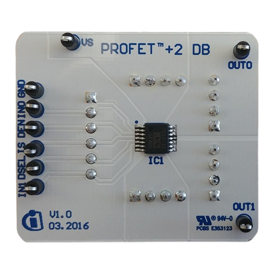
+2 12V daughterboard [DB] . . . . . . . . . . . . . . . . . . . . . . . . . . . . . . . . . . . . . . . . . . . . . . . . . . . . . . 7
™
+2 12V evaluation kit . . . . . . . . . . . . . . . . . . . . . . . . . . . . . . . . . . . . . . . . . 8
™
+2 12V GUI . . . . . . . . . . . . . . . . . . . . . . . . . . . . . . . . . . . . . . . . . . . . . . . . . . . . . . . . . . . . . . . . . . .13
Please read the Important Notice and Warnings at the end of this document
™
+2 12V customer evaluation kit and to
™
+2 12V customer evaluation kit.
™
+2 12V customer evaluation kit with or without the
Rev. 1.01
2019-06-27
Advertisement
Table of Contents

Related Manuals for Infineon PROFET+2 12V


Summary of Contents for Infineon PROFET+2 12V
-
Page 1: Table Of Contents
Installation of the Infineon Toolbox ........ -
Page 2: Overview
Customer evaluation kit description ™ PROFET +2 12V 1 Overview Overview The PROFET ™ +2 12V customer evaluation kit consists of a motherboard [MB] and a daughterboard [DB]. The DB is plugged onto the MB, as seen in Figure 1 below. -
Page 3: Evaluation Kit Description
Customer evaluation kit description ™ PROFET +2 12V 2 Evaluation kit description Evaluation kit description Figure 2 below illustrates the location of the connectors and jumpers. The jumpers’ names are printed next to them and will be explained in more detail (see Chapter 2.1). -
Page 4: Detailed Information On The Evaluation Kit
PIN 1. The description of the positions is given in Table 3 (J_RGND [4]) and Table 4 (J_SENSE1, J_SENSE2 [5]). Figure 4 Jumper positions The Infineon µIO-Stick can be ordered at https://www.ehitex.de/en/ Application Note Rev. 1.01 2019-06-27... - Page 5 Customer evaluation kit description ™ PROFET +2 12V 2 Evaluation kit description Table 3 below lists the description of the three jumper positions of J_RGND [4], as well as the position of PIN 1. Table 3 J_RGND [4] - Jumper positions Description ™...
-
Page 6: Motherboard [Mb]
Customer evaluation kit description ™ PROFET +2 12V 2 Evaluation kit description ™ PROFET +2 12V motherboard [MB] The following block diagram (Figure 5) gives an overview of the locations of jumpers and connectors. GND circuit OUT0 J_GND OUT1 Device GND DSEL0 Out0 Out1... -
Page 7: Daughterboard [Db]
For further information see Chapter 2.1 ™ µIO-Connectors The PROFET +2 12V demoboard can either be used with external sources or with the µIO-stick by means of the Infineon Config Wizard (see Chapter 4). For further information see Chapter 2.1 ™... -
Page 8: Quickstart Guide: Profet ™ +2 12V Evaluation Kit
Customer evaluation kit description ™ PROFET +2 12V ™ 3 Quickstart guide: PROFET +2 12V evaluation kit ™ Quickstart guide: PROFET +2 12V evaluation kit ™ Plug the PROFET +2 12V DB onto the MB Connect a power supply to (4.1 V – 28 V) Connect digital supply (LOW: 0 V, HIGH: 3.3 V ≤... -
Page 9: Software (Optional)
By following the link in the previous Chapter 4 , the installation site of the Infineon Toolbox is reached. Note that Java 8 32bit must be installed on the system, otherwise the Toolbox will not start. Install the Toolbox by clicking the Installer (<version>) button, which is highlighted. -
Page 10: Install The Config Wizard For Ipd
4 Software (optional) 4.1.2 Install the Config Wizard for IPD Launch the Infineon Toolbox and go to the Manage tools tab and type Config Wizard for IPD into the search bar. The Toolbox will find one application (see Figure Figure 9 Infineon Toolbox - Config Wizard for IPD Click the Install button and accept the license agreement (after reading it carefully). -
Page 11: Gui Description
4.2.1 µIO-stick The tool which is needed to connect the Config Wizard to the device is the Infineon µIO-Stick. The μIO-Stick is delivered with a 16-pin ribbon cable to connect the µIO-Stick to the MB (see Figure 11 Figure 11 Infineon µIO-Stick with ribbon cable... -
Page 12: Start-Up Screen
Customer evaluation kit description ™ PROFET +2 12V 4 Software (optional) 4.2.2 Start-up screen The start-up screen of the Config Wizard for IPD consists of button-tiles which are named after the product families as seen in Figure 13 below. Figure 13 Config Wizard for IPD - start-up screen Note: The number of tiles seen may vary due of extensions (new product families and so on). -
Page 13: Profet +2 12V Gui
Customer evaluation kit description ™ PROFET +2 12V 4 Software (optional) ™ 4.2.3 PROFET +2 12V GUI ™ The GUI for the PROFET +2 12V consists of buttons, which control the GPIOs of the µIO-Stick. The GPIOs are connected to the pins of the device (as INx, DEN and DSELx), therefore the buttons control the logic state at the ™... - Page 14 Customer evaluation kit description ™ PROFET +2 12V 4 Software (optional) ™ Figure 17 PROFET +2 12V functional view – IN0 as logic input, IN1 as PWM input The possibility to display the sense current [IS] is also given. The sense current is converted to a measurable voltage over a resistor.
- Page 15 Customer evaluation kit description ™ PROFET +2 12V 4 Software (optional) ™ Figure 19 PROFET +2 12V functional view – Device selection ™ Figure 20 PROFET +2 12V functional view – Switching from I to I The small box with title Filter activated? (see Figure 21), which is included within the diagnosis display section is used to specify whether sense filtering is activated on the MB (see...
-
Page 16: Appendix
Customer evaluation kit description ™ PROFET +2 12V 5 Appendix Appendix Figure 22 Motherboard schematic Figure 23 PCB top view Application Note Rev. 1.01 2019-06-27... - Page 17 Figure 24 PCB bottom view Table 6 Available Demoboards Product ISaR name Internet link ™ PROFET +2 12V PROFET PLUS2 MOTH BRD 4Ch https://www.infineon.com/profet-plus2-moth-brd motherboard BTS7008-1EPA BTS7008-1EPA DAUGH BRD https://www.infineon.com/bts7008-1epa-daugh-brd BTS7010-1EPA BTS7010-1EPA DAUGH BRD https://www.infineon.com/bts7010-1epa-daugh-brd BTS7012-1EPA BTS7012-1EPA DAUGH BRD https://www.infineon.com/bts7012-1epa-daugh-brd...
-
Page 18: Revision History
Customer evaluation kit description ™ PROFET +2 12V 6 Revision history Revision history Document version Date of release Description of changes ™ ™ 1.01 2019-06-27 updated family name (PROFET +2 → PROFET +2 12V) ™ 1.00 2019-06-11 PROFET +2 customer evaluation kit description available Application Note Rev. -
Page 19: Disclaimer
Infineon Technologies, All Rights Reserved. any kind, including without limitation warranties of Infineon Technologies’ products may not be used in non-infringement of intellectual property rights of any any applications where a failure of the product or third party.
Need help?
Do you have a question about the PROFET+2 12V and is the answer not in the manual?
Questions and answers