ETC Echo Manual
- Installation manual (9 pages) ,
- Installation manual (8 pages) ,
- Installation manual (3 pages)
Advertisement
Overview
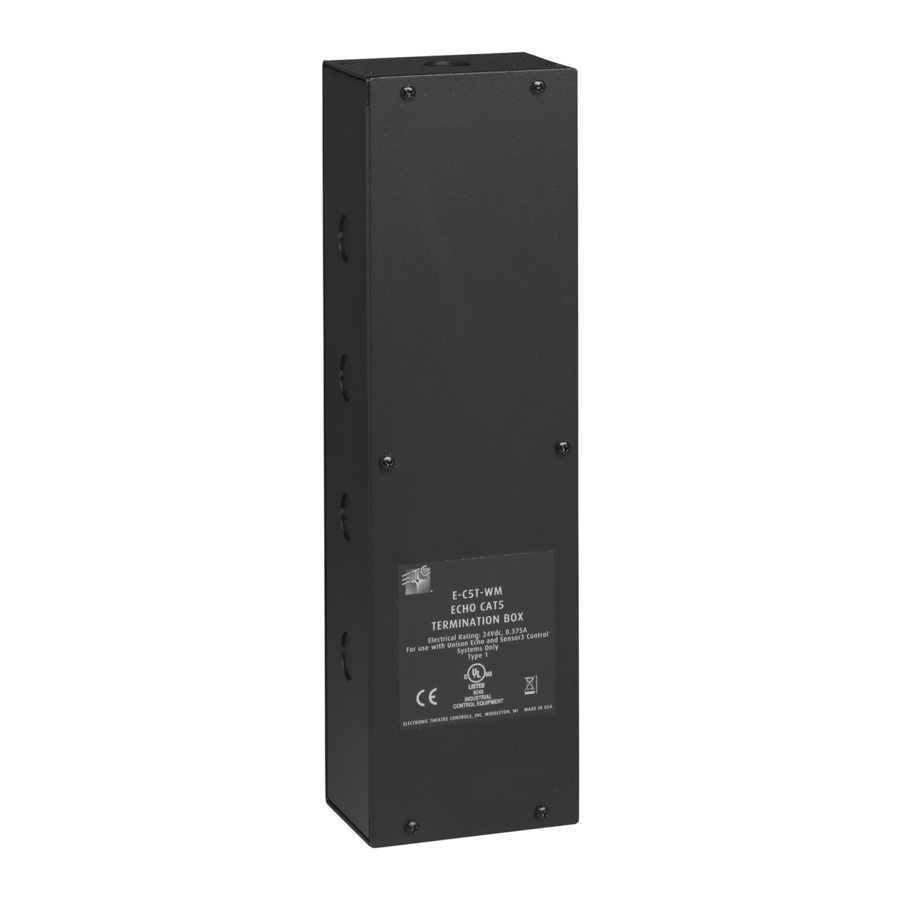
The EchoConnect Cat5 Termination Box is intended for installation on a wall or flat vertical surface, typically near or directly next to a wall-mount Echo Station Power Supply.
This termination box facilitates termination of up to 16 runs of Category 5 (or equivalent) cable on the EchoConnect communication bus.
The following supplies are included for installation convenience:
- 1.8 m (6 ft) of Belden 8471 cable
- Six-position screw terminal connector J3263-F (x1)
For use with ETC Echo Control Systems, powered by an Echo station power supply.

Mount Box to Wall
This termination box is provided with four knockouts on each long side, sharing the same conduit entry locations as the wall-mount Echo Station Power Supply. All wiring terminations are accessible from the front with the cover removed. If you are mounting this box directly next to the wall-mount Echo Station Power Supply, use appropriate attaching hardware and wire protection hardware (not provided).

- Remove the six screws securing the front cover to the box.
- Align the unit to the wall and mark the mounting keyholes. Alternatively, see the dimensioned drawing at right.
- Drill the mounting holes and install the mounting hardware (not provided). Expose at least 19 mm (3/4 in) of threads for mounting the unit.
- Attach the termination box to the mounting hardware, where the back side of the unit is flush to the wall, and then tighten the mounting hardware.
Rough-In Conduit and Wiring
 Note: NEC Class 2 product is to be wired in accordance to NEC Article 725 and local jurisdiction requirements. Follow all local codes and restrictions.
Terminations include:
- EchoConnect (Belden 8471 twisted pair) installed between this termination box and the adjacent Echo Station Power Supply. This wire pair is provided.
- Category 5 (or equivalent) cable installed between this termination box and each EchoConnect wire run. Up to 16 runs of EchoConnect are supported. See etcconnect.com/Support/CableCross-Database.aspx for more information.
- ESD ground wire, 2.5 mm (14 AWG) is recommended, between this termination box (ESD ground bar) and any Echo product (Class 2 only) on the communication bus that is not installed entirely in grounded metal conduit.
Terminate Wiring
Connect Cat5 Inputs
Echo products that are installed for use with Cat5 control wire for the EchoConnect communication bus are supplied with a Cat5 Station Termination Kit (ETC part number 7186A1237). This termination kit includes all of the parts and instructions that are required to complete EchoConnect terminations when using Cat5 cable.
The last station in the EchoConnect wire run does not require use of the second eight-position clamp style connector (part number J30243) provided in the Cat5 Station Termination Kit. Terminate the spare connector using the following instructions:
- Label your cables (i.e. E1) and strip 50 mm (2 in) of the outer cable jacket.

- Fold or cut the shield back to access the conductors.

- Fan out the wires while maintaining the twisted pair as close to the connector as possible.

- Strip the ends of each wire 10 mm (0.4 in).
![]()
- Insert the conductors. Ensure that all eight conductors are terminated.
- For solid core wire, simply insert the conductor.
- For stranded wire, use a 3 mm (1/8 in) small flat blade screwdriver to press down the corresponding button.


Use the spare connector to terminate the EchoConnect wire run to the Cat5 termination box.

- Connect the clamp sytle connector you prepared with the Cat5 wires to any of the 16 available Cat5 input receptacles.
- Repeat for each EchoConnect wire run using Cat5 control wire in the system.
- When an Echo product (Class 2 only) on the communication bus is not installed in grounded metal conduit, connect an ESD ground wire (2.5 mm2 [14 AWG] is recommended) between the product and the ESD ground termination bar. Torque this connection to 20 lb-in.
Connect EchoConnect to the Echo Station Power Supply
- Route the supplied Belden 8471 twisted pair between this termination box and the adjacent Echo Station Power Supply.
- Remove the six-position screw connector from the bottom position of the termination box.
- Strip 9–10 mm (3/8 in) from each wire end in the supplied Belden 8471.
- Maintain the wire twist as close to the connection as possible, and then insert the white wire into the data + terminal (1) and the black wire into the data - terminal (2). Tighten the screws firmly onto each wire, and then replace the connector to the board.
- Remove the two-position screw connector from the Echo Station Power Supply termination board.
- Maintain the wire twist as close to the connection as possible, and then insert the white wire into the data + terminal (1) and the black wire into the data - terminal (2). Tighten the screws firmly onto each wire, and then replace the connector to the receptacle on the board.
Final Installation
Replace the cover to the termination box and secure it in place using the six screws previously removed. See the related station power supply installation documentation for power up and test procedures.
Web etcconnect.com
Support support.etcconnect.com
Contact etcconnect.com/contactETC
Documents / Resources
References
Cable Cross
ETC - Theatre, Film, Studio and Architectural Lighting
![support.etcconnect.com]() Home - Electronic Theatre Controls Inc
Home - Electronic Theatre Controls IncContacting ETC
Download manual
Here you can download full pdf version of manual, it may contain additional safety instructions, warranty information, FCC rules, etc.
Advertisement


Need help?
Do you have a question about the Echo and is the answer not in the manual?
Questions and answers