Sign In
Upload
Download
Table of Contents
Contents
Add to my manuals
Delete from my manuals
Share
URL of this page:
HTML Link:
Bookmark this page
Add
Manual will be automatically added to "My Manuals"
Print this page
×
Bookmark added
×
Added to my manuals
Manuals
Brands
Supermicro Manuals
Chassis
SC813MF2 Series
User manual
Supermicro SC813MF2 Series User Manual
Hide thumbs
1
2
3
Table Of Contents
4
5
6
7
8
9
10
11
12
13
14
15
16
17
18
19
20
21
22
23
24
25
26
27
28
29
30
31
32
33
34
35
36
37
38
39
40
41
42
43
44
45
46
47
48
49
50
51
52
53
54
55
56
57
58
page
of
58
Go
/
58
Contents
Table of Contents
Bookmarks
Table of Contents
Table of Contents
Contacting Supermicro
Chapter 1 Introduction
Overview
Unpacking the System
Chassis Features
Control Panel
Chassis Front
Drive Carrier Indicators
Chassis Rear
Status Indicator
Where to Get Replacement Components
Returning Merchandise for Service
Chapter 2 Chassis Installation
Overview
Preparing for Setup
Choosing a Setup Location
Rack Precautions
System/Chassis Precautions
Rack Mounting Considerations
Ambient Operating Temperature
Airflow
Mechanical Loading
Circuit Overloading
Reliable Ground
Installing the Rails
Identifying the Rails
Installing the Chassis into the Rack
Removing the Chassis from the Rack
Chapter 3 Maintenance and Component Installation
Removing Power
Accessing the System
Chassis Components
Installing Drives
System Cooling
Fans
Optional Air Shrouds (Not Included)
Installing the Motherboard
Permanent and Optional Standoffs
Pcie Expansion Cards
Backplane
Power Distributor
Power Supply
Power Supply Leds
Appendix A Standardized Warning Statements for AC Systems
Advertisement
Quick Links
Download this manual
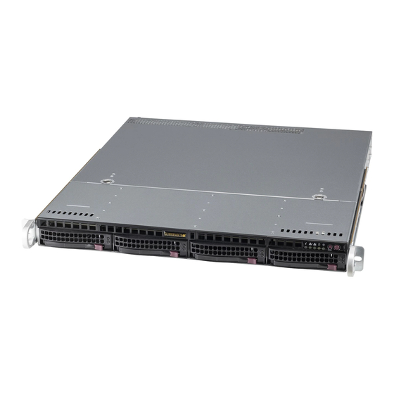
SC813MF2
Chassis Series
CSE-813MF2-R_RCB
CSE-813MF2_RCB
USER'S MANUAL
Revision 1.0
Table of
Contents
Previous
Page
Next
Page
1
2
3
4
5
Advertisement
Table of Contents
Need help?
Do you have a question about the SC813MF2 Series and is the answer not in the manual?
Ask a question
Questions and answers
Related Manuals for Supermicro SC813MF2 Series
Chassis Supermicro SC811i-280 User Manual
Sc811 chassis series (54 pages)
Chassis Supermicro SC818 User Manual
Chassis series (32 pages)
Chassis Supermicro SC812L-280U User Manual
Sc812l chassis series (52 pages)
Chassis Supermicro SC815 series User Manual
(54 pages)
Chassis Supermicro SC815S-560B User Manual
Sc815 chassis series (80 pages)
Chassis Supermicro SC815B User Manual
(55 pages)
Chassis Supermicro SUPERO SC813M Series User Manual
(84 pages)
Chassis Supermicro SUPERO SC813MTQ-350CB User Manual
(84 pages)
Chassis Supermicro SC825MS-R700LPB User Manual
Sc825m chassis series (63 pages)
Chassis Supermicro SC825MTQ-R700LPB User Manual
Sc825m chassis series (78 pages)
Chassis Supermicro SC846BE2C-R1K28B User Manual
(160 pages)
Chassis Supermicro SC825TQC-R1K03WB User Manual
Sc825 series chassis (86 pages)
Chassis Supermicro SC846BE1C-R1K23B User Manual
(160 pages)
Chassis Supermicro SC826 Series User Manual
(146 pages)
Chassis Supermicro SC836BE1C-R1K23B User Manual
(146 pages)
Chassis Supermicro SC842 Series User Manual
(85 pages)
This manual is also suitable for:
Cse-813mf2-r rcb
Cse-813mf2 rcb
Table of Contents
Print
Rename the bookmark
Delete bookmark?
Delete from my manuals?
Login
Sign In
OR
Sign in with Facebook
Sign in with Google
Upload manual
Upload from disk
Upload from URL


Need help?
Do you have a question about the SC813MF2 Series and is the answer not in the manual?
Questions and answers