
Related Manuals for Supermicro SC825MS-R700LPB


Summary of Contents for Supermicro SC825MS-R700LPB
- Page 1 UPER ® SC825M Chassis Series SC825MTQ-R700LPB SC825MS-R700LPB SC825MTQ-R700UB USER’S MANUAL 1.0a...
- Page 2 Please Note: For the most up-to-date version of this manual, please see our web site at www.supermicro.com. Super Micro Computer, Inc. ("Supermicro") reserves the right to make changes to the product described in this manual at any time and without notice. This product, including software, if any, and documentation may not, in whole or in part, be copied, photocopied, reproduced, translated or reduced to any medium or machine without prior written consent.
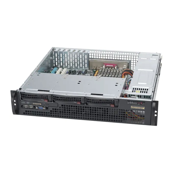
- Page 3 SC825M 2U chassis. Instal- lation and maintenance should be performed by experienced technicians only. Supermicro’s SC825M 2U chassis is a short-depth chassis with a unique and highly- optimized design. The chassis is equipped with a redundant 700W high efficiency power supply for superb power savings.
-
Page 4: Manual Organization
SC825M Chassis Manual Manual Organization Chapter 1: Introduction The first chapter provides a checklist of the main components included with this chassis and describes the main features of the SC825M chassis. This chapter also includes contact information. Chapter 2: System Safety This chapter lists warnings, precautions, and system safety. - Page 5 Preface Appendices This section lists compatible cables, power supply specifications, and compatible backplanes. Not all compatible backplanes are listed. Refer to our Web site for the latest compatible backplane information. Appendix A: Chassis Cables Appendix B: Power Supply Specifications Appendix C: Backplane Specifications...
-
Page 6: Table Of Contents
Manual Table of Contents Chapter 1 Introduction Overview ......................1-1 Shipping List ....................1-1 Contacting Supermicro ..................1-2 Returning Merchandise for Service ..............1-3 Chapter 2 System Safety Overview ......................1 Warnings and Precautions ................. 1 Preparing for Setup .................... 1 Electrical Safety Precautions ................ - Page 7 Preface I/O Shield ......................5-6 Hard Drive Tray and DVD-ROM Drive Removal ..........5-7 Permanent and Optional Standoffs ..............5-9 Add-on Card/Expansion Slot Setup .............. 5-10 Installing the Air Shroud .................5-11 Checking the System Air Flow ..............5-12 Completing the Installation ................5-13 System Fans ....................
-
Page 8: Chapter 1 Introduction
Chapter 1: Introduction Chapter 1 Introduction Overview Supermicro’s SC825M 2U chassis features a unique and highly-optimized design. The chassis is equipped with a high-efficiency power supply. High performance fans provide ample optimized cooling for the chassis. Shipping List Part Numbers Please visit the following link for the latest shiping lists and part numbers for your par- ticular chassis model http://www.supermicro.com/products/chassis/2U/?chs=825M... -
Page 9: Contacting Supermicro
Super Micro Computer, Inc. 980 Rock Ave. San Jose, CA 95131 U.S.A. Tel: +1 (408) 503-8000 Fax: +1 (408) 503-8008 Email: marketing@supermicro.com (General Information) support@supermicro.com (Technical Support) Web Site: www.supermicro.com Europe Address: Super Micro Computer B.V. Het Sterrenbeeld 28, 5215 ML... -
Page 10: Returning Merchandise For Service
For faster service, RMA authorizations may be requested online (http://www. supermicro.com/support/rma/). Whenever possible, repack the chassis in the original Supermicro carton, using the original packaging material. If these are no longer available, be sure to pack the chassis securely, using packaging material to surround the chassis so that it does not shift within the carton and become damaged during shipping. - Page 11 SC825M Chassis Manual Notes...
-
Page 12: Chapter 2 System Safety
Chapter 2: System Safety Chapter 2 System Safety Overview This chapter provides a quick setup checklist to get your chassis up and running. Following the steps in order given should enable you to have your chassis setup and operational within a minimal amount of time. This quick set up assumes that you are an experienced technician, famailiar with common concepts and terminology. - Page 13 SC825M Chassis Manual • Be aware of the locations of the power on/off switch on the chassis as well as the room’s emergency power-off switch, disconnection switch or electrical outlet. If an electrical accident occurs, you can then quickly remove power from the system.
-
Page 14: General Safety Precautions
Chapter 2: System Safety General Safety Precautions • Keep the area around the chassis clean and free of clutter. • Place the chassis top cover and any system components that have been re- moved away from the system or on a table so that they won’t accidentally be stepped on. - Page 15 SC825M Chassis Manual • Handle a board by its edges only; do not touch its components, peripheral chips, memory modules or contacts. • When handling chips or modules, avoid touching their pins. • Put the serverboard and peripherals back into their antistatic bags when not in use.
-
Page 16: Chapter 3 Chassis Components
SAS/SATA or SCSI. For more information regarding compat- ible backplanes, view the appendices found at the end of this manual. In addition, visit our Web site for the latest information: http://www.supermicro.com. Fans The SC825M chassis accepts four system fans. System fans for SC825M chassis are powered from the serverboard. -
Page 17: Mounting Rails
Supermicro Authorized Distributors / System Integrators / Resellers. A list of Supermicro Authorized Distributors / System Integrators /Reseller can be found at: http://www.supermicro.com. Click the Where... -
Page 18: Chapter 4 System Interface
Chapter 4: System Interface Chapter 4 System Interface Overview This chasis includes LEDs on the control panel and drive carriers that indicate the activity and health of specific components. Control Panel Buttons There are two buttons located on the front of the chassis: a reset button and a power on/off button. -
Page 19: Control Panel Leds
SC825M Chassis Manual • Reset: The reset button is used to reboot the system. • Power: The main power switch is used to activate or deactivate power to the server system. Turning off system power with this button removes the main power but keeps standby power. - Page 20 Chapter 4: System Interface • Overheat/Fan Fail When Flashing: This LED indicates a fan failure. When Continuously On (not flashing): This LED indicates an overheat condi- tion caused by cables obstructing the airflow in the system or the ambient room temperature being too warm.
-
Page 21: Drive Carrier Leds
SC825M Chassis Manual • HDD: Indicates IDE channel activity. SAS/SATA drive, SCSI drive, and/or DVD- ROM drive activity when flashing. • Power: Indicates power is being supplied to the system's power supply units. This LED should normally be illuminated when the system is operating. Drive Carrier LEDs Your chassis uses SAS/SATA or SCSI drives, but not both. -
Page 22: Chapter 5 Chassis Setup And Maintenance
Chapter 5: Chassis Setup and Maintenance Chapter 5 Chassis Setup and Maintenance Overview This chapter covers the steps required to install components and perform main- tenance on the chassis. The only tools you will need to install components and perform maintenance is a Phillips screwdriver and under certain circumstances, a hex wrench Print this page to use as a reference while setting up your chassis. -
Page 23: Removing The Chassis Cover
SC825M Chassis Manual Removing the Chassis Cover Remove this Screw Remove this Screw Figure 5-1: Removing the Chassis Cover Removing the Chassis Cover: Remove the two screws holding the chassis in place. Slide the cover toward the rear of the chassis and lift the cover from the unit. Warning: Except for short periods of time, do NOT operate the server without the cover in place. -
Page 24: Installing The Hard Drives
Chapter 5: Chassis Setup and Maintenance Installing the Hard Drives Removing the Hard Drive Trays from the Chassis Press the release button on the drive tray. This extends the drive tray handle. Use the handle to pull the drive out of the chassis. - Page 25 SC825M Chassis Manual Figure 5-3: Chassis Drive Tray The drives are mounted in drive carriers to simplify their installation and removal from the chassis. These carriers also help promote proper airflow for the drive bays. Warning: Except for short periods of time (swapping hard drives), do not operate the server with the hard drives empty.
- Page 26 Chapter 5: Chassis Setup and Maintenance Install a new drive into the carrier with the printed circuit board side facing down so that the mounting holes align with those in the carrier. Secure the hard drive by tightening all six screws. Replace the drive tray into the chassis.
-
Page 27: Installing The Motherboard
SC825M Chassis Manual Installing the Motherboard This section describes how to install the motherboard to the chassis. To do this, you are required to remove the hard drive tray. I/O Shield Figure 5-6: I/O Shield Placement I/O Shield The I/O shield holds the motherboard ports in place. Install the I/O shield before you install the motherboard. -
Page 28: Hard Drive Tray And Dvd-Rom Drive Removal
Chapter 5: Chassis Setup and Maintenance Hard Drive Tray Figure 5-7: Hard Drive Tray Screws Hard Drive Tray and DVD-ROM Drive Removal Before insalling the mother board, you must remove the hard drive tray and the DVD-ROM drive. Removing the Hard Drive Tray Pull all three hard drives from the hard drive tray. - Page 29 SC825M Chassis Manual The DVD-ROM is connected to a comport USB tray. Both must be removed and replaced as a unit. Removing the DVD-ROM Drive Unit Locate and remove the screw holding the DVD-ROM in place. If necessary, disconnect any cables to the DVD-ROM and Comport tray. Slide the DVD-ROM and comport tray toward the rear of the chassis, sliding the tray out of the slotted holes on the bottom of the chassis.
-
Page 30: Permanent And Optional Standoffs
Flat head Round head Round head Pan head 6-32 x 5 mm 2.6 x 5 mm 6-32 x 5 mm 3 x 5 mm Chapter 5: Chassis Setup and Maintenance [0.197] [0.197] [0.197] [0.197] RAIL Permanent and Optional Standoffs Standoffs prevent short circuits by securing space between the motherboard and the chassis surface. -
Page 31: Add-On Card/Expansion Slot Setup
SC825M Chassis Manual Add-on Card/Expansion Slot Setup Add-on/Expansion Card Slots Figure 5-11: Remove the Add-on Card Slot screw SC825M chassis include seven slots for add-on cards and expansion cards. Installing an Add-on or Expansion Card: Confirm that each add on card you are installing includes a standard "L" bracket. -
Page 32: Installing The Air Shroud
Chapter 5: Chassis Setup and Maintenance Installing the Air Shroud Air Shroud Perforations Figure 5-14: Air Shroud for SC825M Chassis Air shrouds concentrate airflow to maximize fan efficiency. The SC825M chassis air shroud does not require screws to set up. Installing the Air Shroud Each air shroud includes perforations that can be removed to accommodate motherboard components. -
Page 33: Checking The System Air Flow
SC825M Chassis Manual Checking the System Air Flow Proper airflow allows the chassis to keep the server components cooled and prevent damage. Use the following steps to check airflow after setup and in the unlikely event the chassis needs to be serviced. Checking the Server's Air Flow Make sure no cables or foreign objects obstruct air flow through the chassis. -
Page 34: Completing The Installation
Chapter 5: Chassis Setup and Maintenance Completing the Installation Once you the air shroud is properly installed, you must do the following Completing the Installation Replace the DVD-ROM drive unit and connect the DVD-ROM drive to the motherboard. Replace the hard drive tray. The hard drive tray includes a SAS/SATA or SCSI backplane. -
Page 35: System Fans
SC825M Chassis Manual System Fans The 825M chassis includes four fans for cooling and air circulation. A dummy fan is included as a place holder. System Fans Rubber Fan Feet Dummy Fan Figure 5-13: System Fan and Dummy Fan in Fan Tray Replacing a System Fan If necessary, open the chassis while the power is running to determine which fan needs replacing. - Page 36 Chapter 5: Chassis Setup and Maintenance Note: The 825M Chassis includes four pre-installed fans. An extra slot is included for an optional fifth fan. Figure 5-14: Placing the System Fan Place the new fan into the vacant space in the housing while making sure the arrows on the top of the fan (indicating air direction) point in the same direc- tion as the arrows on the other fans.
-
Page 37: 5-10 Power Supply
The 825M chassis models include a redundant power supply. Power supplies can be replaced without powering down the system. Replacement units can be ordered directly from Supermicro (see contact information in the Preface). Release Tab Figure 5-15: Removing the Power Supply The 825M chassis includes a redundant power supply. - Page 38 Chapter 5: Chassis Setup and Maintenance Replace the failed power module with a new unit. To do this, push the new power supply module into the power bay until you hear a click. Plug the AC power cord back into the module and power up the server. 5-17...
-
Page 39: Replacing The Power Distributor
SC825M Chassis Manual Figure 5-16: Replacing the Power Distributor Replacing the Power Distributor The power distributor provides failover and power supply redundancy. In the unlikely event you must replace the power distributor, do following Replacing the Power Distributor Power down the server and remove the plug from the wall socket or power strip. -
Page 40: 5-11 Other Components
Chapter 5: Chassis Setup and Maintenance 5-11 Other Components DVD-ROM Drive and USB Comport The 825M chassis models include a slim DVD-ROM and USB Comport drive. In the unlikely event you must change the DVD-ROM drive, do the following Replacing the DVD-ROM and USB Comport Follow the instruction for removing the DVD-ROM unit found in the section of this manual titled Removing the DVD-ROM Drive Unit. -
Page 41: Installing An Optional Floppy Or Hard Disk Drive
SC825M Chassis Manual Installing an Optional Floppy or Hard Disk Drive The SC825M chassis models include two open slots for an optional floppy drive and /or hard disk drive(s). To utilize these slots, the dummy drive and the slot cover must be removed. -
Page 42: 5-12 Optional Front Bezel
The SC825M chassis supports an optional full-face locking front bezel for added se- curity. The front bezel is not included with the SC825M chassis, but can be ordered seperately by visiting the Supermicro Web site at www.supermicro.com, clicking on the Where to Buy link and referencing part number MCP-210-82503-0B. -
Page 43: Chapter 6 Rack Installation
Chapter 6: Rack Installation Chapter 6 Rack Installation Overview This chapter provides a quick setup checklist to get your chassis up and running. Following these steps in the order given should enable you to have the system operational within a minimum amount of time. Unpacking the System You should inspect the box the chassis was shipped in and note if it was damaged in any way. -
Page 44: Rack Precautions
SC825M Chassis Manual • This product is for installation only in a Restricted Access Location (dedicated equipment rooms, service closets and the like). Warnings and Precautions! Rack Precautions • Ensure that the leveling jacks on the bottom of the rack are fully extended to the floor with the full weight of the rack resting on them. -
Page 45: Rack Mounting Considerations
Chapter 6: Rack Installation Rack Mounting Considerations Ambient Operating Temperature If installed in a closed or multi-unit rack assembly, the ambient operating tempera- ture of the rack environment may be greater than the ambient temperature of the room. Therefore, consideration should be given to installing the equipment in an environment compatible with the manufacturer’s maximum rated ambient tempera- ture (Tmra). -
Page 46: Rack Mounting Instructions
SC825M Chassis Manual Rack Mounting Instructions This section provides information on installing the 825M chassis into a rack unit with the rails provided. There are a variety of rack units on the market, which may mean the assembly procedure will differ slightly. You should also refer to the installation instructions that came with the rack unit you are using. -
Page 47: Outer Rack Rails
Chapter 6: Rack Installation Secure to the Front of the Rack Secure to the Rear of the Rack Attach Outer Racks together Figure 6-1. Assembling the Outer Rails Outer Rack Rails Outer rails attach to the server rack and hold the server in place. The outer rails for the SC825M chassis extend between 26"... - Page 48 SC825M Chassis Manual Figure 6-2: Installing the Rack Rails Installing the Chassis into a Rack Confirm that chassis includes the inner rails and rail extensions. Also, confirm that the outer rails are installed on the rack. Line chassis rails with the front of the rack rails. Slide the chassis rails into the rack rails, keeping the pressure even on both sides (you may have to depress the locking tabs when inserting).
- Page 49 Chapter 6: Rack Installation Figure 6-3: Installing the Rack Rails...
- Page 50 SC825M Chassis Manual Notes...
- Page 51 A variety of cables are supported for your chassis system. In order to obtain the most up-to-date information on compatible cables, compoments and configurations, refer to the manufacturer of the motherboard you are using and to our Web site at: www.supermicro.com.
- Page 52 SC825M Chassis Manual A-3 Compatible Cables These cables are compatible with the SC825M Chassis. Alternate SAS/SATA Cables Some compatible motherboards have different connectors. If your motherboard has only one SAS connector that the SAS/SATA cables must share, use one of the following cables.
-
Page 53: Extending Power Cables
Appendix A: Chassis Cables Extending Power Cables Although Super Micro chassis are designed with to be efficient and cost-effective, some compatible motherboards have power connectors located in different areas. To use these motherboards you may have to extend the power cables to the mother boards. - Page 54 SC825M Chassis Manual A-5 Chassis Screws The accessory box includes all the screws needed to setup your chassis. This section include descriptions of the most common screws used. Your chassis may not require all the parts listed. HARD DRIVE Flat head Pan head 6-32 x 5 mm 6-32 x 5 mm...
- Page 55 Appendix B: Power Supply Specifications Appendix B SC825M Power Supply Specifications SC825M 700W (Redundant) MFR Part # PWS-0065 100 - 240V Rated AC Voltage 50 - 60Hz 9.5 - 4.5 Amp +5V standby 4 Amp +12V 58 Amp...
- Page 56 SC825M Chassis Manual Notes...
-
Page 57: Appendix C Backplane Specifications
Appendix C: Backplane Specifications Appendix C Backplane Specifications To avoid personal injury and property damage, carefully follow all the safety steps listed below when accessing your system or handling the components. C-1 ESD Safety Guidelines Electric Static Discharge (ESD) can damage electronic components. To prevent dam- age to your system, it is important to handle it very carefully. -
Page 58: Front Connectors
SC825M Chassis Manual C-4 Front Connectors and Jumpers Front View JP44 JP33 JP47 UPER SAS818TQ JP50 JP40 REV 1.00 JP42 JP34 +12V +12V JP29 JP18 JP10 Front Connectors 1. JP10: Backplane Main PWR (4-Pin) 2. JP51: Sideband Connector 3. JP44: I C Connector 4. - Page 59 Appendix C: Backplane Specifications C-5 Front Connector and Pin Definitions #1. Backplane Main Power Connector Backplane Main Power The 4-pin connector, designated JP10, 4-Pin Connector (JP10) provides power to the backplane. See the table on the right for pin definitions. Pin# Definition +12V...
- Page 60 SC825M Chassis Manual #5. CD-ROM/Floppy 4-Pin Connectors CD-ROM/ FDD Power The 4-pin connectors, designated J9 and 4-Pin Connector (J9 and J10) J10, provide power to the CD-ROM and Pin# Definition floppy drives. See the table on the right +12V for pin definitions. 2 and 3 Ground #6.
-
Page 61: Jumper Settings
Appendix C: Backplane Specifications C-6 Front Jumper Locations and Pin Definitions JP33 JP50 JP42 JP40 JP29 JP44 JP33 JP47 JP50 UPER SAS818TQ JP40 REV 1.00 JP42 JP34 JP34 +12V +12V JP29 JP18 JP10 JP18 Explanation of Jumpers Connector To modify the operation of the backplane, Pins jumpers can be used to choose between optional settings. - Page 62 SC825M Chassis Manual C and SGPIO Modes and Jumper Settings This backplane can utilize I C or SGPIO. I C is the default mode and can be used without making changes to your jumpers. The following information details which jumpers must be configured to use SGPIO mode or restore your backplane to I mode.
- Page 63 Appendix C: Backplane Specifications C-7 Rear Connectors and LED Indicators Rear Connector Locations BAR CODE SAS #0 SAS #1 SAS #2 SAS#0 SAS#1 SAS#2 Rear Connector/LED Indicator Descriptions Rear SAS Connectors Rear SAS Drive Number Connector SAS#0 SAS/SATA HHD #0 SAS#1 SAS/SATA HHD #1 SAS#2...
Need help?
Do you have a question about the SC825MS-R700LPB and is the answer not in the manual?
Questions and answers