Table of Contents
Advertisement
Quick Links
Advertisement
Table of Contents

Related Manuals for Supermicro SC815B


Summary of Contents for Supermicro SC815B
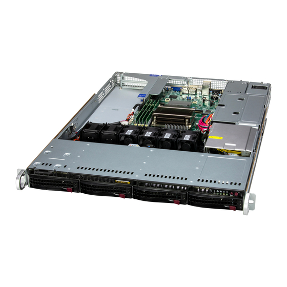
- Page 1 SC815B Chassis Series CSE-815BTQC-R860W USER’S MANUAL Revision 1.0...
- Page 2 State of California, USA. The State of California, County of Santa Clara shall be the exclusive venue for the resolution of any such disputes. Supermicro's total liability for all claims will not exceed the price paid for the hardware product.
- Page 3 SC815B series chassis. Installation and maintenance should be performed by experienced technicians only. Please refer to the SC815B chassis specifications page on our website for updates on supported memory, processors, and operating systems (http://www.supermicro.com).
-
Page 4: Table Of Contents
Supermicro SC815B Chassis Series User's Manual Contents Contacting Supermicro ......................6 Chapter 1 Introduction 1.1 Overview ..........................7 1.2 Unpacking the System ......................7 1.3 Chassis Features .........................8 Control Panel ........................8 Chassis Front ........................10 Drive Carrier Indicators ....................10 Chassis Rear ........................11 Status Indicator ......................12 1.4 Where to Get Replacement Components ................12... - Page 5 Preface 3.3 Chassis Components ......................23 Installing Drives .........................23 System Cooling .........................26 Fans ..........................26 Installing the Motherboard....................27 Permanent and Optional Standoffs ................27 PCIe Expansion Cards ......................29 Backplane ..........................31 Power Distributor .......................33 Redundant Power Supply System ..................34 Power Supply LEDs ......................34 Power Supply Module .......................35 Appendix A Standardized Warning Statements for AC Systems...
-
Page 6: Contacting Supermicro
Supermicro SC815B Chassis Series User's Manual Contacting Supermicro Headquarters Address: Super Micro Computer, Inc. 980 Rock Ave. San Jose, CA 95131 U.S.A. Tel: +1 (408) 503-8000 Fax: +1 (408) 503-8008 Email: marketing@supermicro.com (General Information) support@supermicro.com (Technical Support) Website: www.supermicro.com Europe Address: Super Micro Computer B.V. -
Page 7: Chapter 1 Introduction
Chapter 1: Introduction Chapter 1 Introduction 1.1 Overview This chapter provides a brief outline of the functions and features of the SC815B chassis. Other materials and information about this product are available at www.supermicro.com. 1.2 Unpacking the System Inspect the box the chassis was shipped in and note if it was damaged in any way. If any equipment appears damaged, please file a damage claim with the carrier who delivered it. -
Page 8: Chassis Features
Supermicro SC815B Chassis Series User's Manual 1.3 Chassis Features Control Panel Power switches and status LEDs are located on the control panel on the front of the chassis. Information LED Reset Button Power LED Unit ID LAN1 LED Power Button... - Page 9 Chapter 1: Introduction Information LED Status Description Red, solid An overheat condition has occurred. Red, blinking at 1Hz Fan failure, check for an inoperative fan. Red, blinking at 0.25Hz Power failure, check for a non-operational power supply. Red, solid, with Power LED Fault detected blinking green Blue and red, blinking at 10 Hz...
-
Page 10: Chassis Front
Supermicro SC815B Chassis Series User's Manual Chassis Front The illustration below shows the features included on the front of the chassis. Control Panel Figure 1-2. Chassis Front View Logical Storage Drive Numbers Item Description Four 3.5" front drive bays (SAS*/SATA) * SAS support available with additional parts. -
Page 11: Chassis Rear
Chapter 1: Introduction Chassis Rear The illustration below shows the features included on the rear of the chassis. Power supply modules display status lights. IPMI COM Port VGA Port USB 2.0 Ports PWS2 PWS1 Unit ID LAN Ports USB 3.0 Ports Figure 1-3. -
Page 12: Status Indicator
(http://www.supermicro.com/ support/rma/). Whenever possible, repack the chassis in the original Supermicro carton, using the original packaging material. If these are no longer available, be sure to pack the chassis securely, using packaging material to surround the chassis so that it does not shift within the carton and become damaged during shipping. -
Page 13: Chapter 2 Chassis Installation
Chapter 2: Rack Installation Chapter 2 Chassis Installation 2.1 Overview This chapter provides advice and instructions for mounting your chassis in a server rack. If your chassis is not already fully integrated with processors, system memory etc., refer to Chapter 3 for details on installing those specific components. Caution: Electrostatic Discharge (ESD) can damage electronic components. -
Page 14: System/Chassis Precautions
Supermicro SC815B Chassis Series User's Manual • In single rack installations, stabilizers should be attached to the rack. In multiple rack in- stallations, the racks should be coupled together. • Always make sure the rack is stable before extending a server or other component fromthe rack. -
Page 15: Circuit Overloading
Chapter 2: Rack Installation Circuit Overloading Consideration should be given to the connection of the equipment to the power supply circuitry and the effect that any possible overloading of circuits might have on overcurrent protection and power supply wiring. Appropriate consideration of equipment nameplate ratings should be used when addressing this concern. -
Page 16: Installing The Rails
Supermicro SC815B Chassis Series User's Manual 2.3 Installing the Rails There are a variety of rack units on the market, which may require a slightly different assembly procedure. This rail set fits a rack between 25.6" and 33" deep. The following is a basic guideline for installing the system into a rack with the rack mounting hardware provided. - Page 17 Chapter 2: Rack Installation Installing the Outer Rails 1. Measure the distance from the front rail of the rack to the rear rail of the rack. 2. Attach a short bracket to the rear side of the right outer rail, and a long bracket to the front side of the right outer rail as shown above on the right.
- Page 18 Supermicro SC815B Chassis Series User's Manual Installing the Rail Assemblies to the Rack 1. After you have installed the short and long brackets to the outer rails, you are ready to install the whole rail assemblies (outer rails with short and long brackets attached) to the rack.
-
Page 19: Installing The Chassis Into The Rack
Chapter 2: Rack Installation 2.4 Installing the Chassis into the Rack Once rails are attached to the chassis and the rack, the chassis is ready to be installed into a rack. 1. Push the inner slides, which are attached to the chassis, into the grooves of the outer slide assemblies that are installed in the rack as shown below. -
Page 20: Removing The Chassis From The Rack
Supermicro SC815B Chassis Series User's Manual Removing the Chassis from the Rack Caution! It is dangerous for a single person to off-load the heavy chassis from the rack without assistance. Be sure to have sufficient assistance supporting the chassis when removing it from the rack. -
Page 21: Chapter 3 Maintenance And Component Installation
Chapter 3: Server Installation Chapter 3 Maintenance and Component Installation This chapter provides instructions on installing and replacing main system components. To prevent compatibility issues, only use components that match the specifications and/or part numbers given. Installation or replacement of most components require that power first be removed from the system. -
Page 22: Accessing The System
Supermicro SC815B Chassis Series User's Manual 3.2 Accessing the System The chassis features a removable top cover for access to the internal components. When performing service on components inside the system, remove the system from the rack and place it on a work bench or desk. Do not service with the system extended from the rack. -
Page 23: Chassis Components
These carriers also help promote proper airflow. Each carrier has a small space on the front to receive a label, orange or purple, to help distinguish SAS/SATA from other protocols. Note: Enterprise level hard disk drives are recommended for use in Supermicro servers. For compatible storage drives, see the corresponding web page. - Page 24 Supermicro SC815B Chassis Series User's Manual Installing a Drive To install a drive into the chassis, first remove the drive carrier from the chassis. 1. Press the release tab to release the drive carrier from its locking position. 2. Pull the drive carrier out from the chassis as shown below:...
- Page 25 Chapter 3: Server Installation 4. Slide a hard drive into the drive carrier, and secure the hard drive to the drive carrier with two screws on each side of the carrier as shown below. Secure the HDD with two screws on each side of the tray. Drive carrier 5.
-
Page 26: System Cooling
Supermicro SC815B Chassis Series User's Manual System Cooling Fans Four 4-cm counter-rotating fans provide the cooling for the system. Each fan unit is actually made up of two fans joined back-to-back, which rotate in opposite directions. This counter- rotating action generates exceptional airflow and works to dampen vibration levels. -
Page 27: Installing The Motherboard
Permanent and Optional Standoffs Standoffs prevent short circuits by creating space between the motherboard and the chassis floor. The SC815B chassis includes permanent standoffs in locations used by most motherboards. These standoffs accept the rounded Phillips head screws included in the accessories packaging. - Page 28 Supermicro SC815B Chassis Series User's Manual Figure 3-5. Installing the Motherboard Installing the Motherboard To install the motherboard, the expansion card assembly needs to be removed first. 1. Review the documentation that came with your motherboard. Become familiar with component placement, requirements, precautions, and cable connections.
-
Page 29: Pcie Expansion Cards
Chapter 3: Server Installation PCIe Expansion Cards The system accepts one low-profile and two full-height expansion cards, mounted on riser cards and brackets. Figure 3-6. Expansion Card Slots in the Chassis Exapnsion Card Configurations Slot Description One low-profile slot for PCIe expansion cards One full-height slot for PCIe expansion cards One full-height slot for PCIe expansion cards Installing an Expansion Card... - Page 30 Supermicro SC815B Chassis Series User's Manual 5. Insert the riser card into the motherboard expansion slot while aligning the riser card bracket with the rear of the chassis. Top Load Riser Bracket 6. Connect cables to the expansion card as necessary.
-
Page 31: Backplane
Chapter 3: Server Installation Backplane The SC815B chassis backplane is located behind the hard drives and in front of the front system fans. In order to change the jumper settings on the backplane, it may be necessary to remove the backplane from the chassis. - Page 32 Supermicro SC815B Chassis Series User's Manual Installing the Backplane into the Chassis 1. Power down the system and unplug the power cords from the rear of the power supply modules. Remove the chassis from the rack and seat it on a work bench (safety area).
-
Page 33: Power Distributor
Chapter 3: Server Installation Power Distributor The SC815B chassis comes equipped with a power distributor. In the unlikely event that you need to replace the power distributor, use the following instructions. Changing the Power Distributor 1. Power down the chassis as described in section 3.1. Unplug the power cords from the rear of the power supplies. -
Page 34: Redundant Power Supply System
Supermicro SC815B Chassis Series User's Manual Redundant Power Supply System The SC815B power supply system will continue to operate if one module fails, this is because the two power supply modules that are installed in the chassis back up each other. However, a failed power supply module should be replaced as soon as possible to maintain redundancy. -
Page 35: Power Supply Module
3. Push the new power supply module into the power bay until it clicks into the locked position. Replace with the same model. Power Supply Module 2 Power Supply Module 1 Release Tab Figure 3-10. Replacing the SC815B Power Supply... -
Page 36: Appendix A Standardized Warning Statements For Ac Systems
Supermicro's Technical Support department for assistance. Only certified technicians should attempt to install or configure components. Read this appendix in its entirety before installing or configuring components in the Supermicro chassis. These warnings may also be found on our website at http://www.supermicro.com/about/... - Page 37 Appendix A: Warning Statements Warnung WICHTIGE SICHERHEITSHINWEISE Dieses Warnsymbol bedeutet Gefahr. Sie befinden sich in einer Situation, die zu Verletzungen führen kann. Machen Sie sich vor der Arbeit mit Geräten mit den Gefahren elektrischer Schaltungen und den üblichen Verfahren zur Vorbeugung vor Unfällen vertraut. Suchen Sie mit der am Ende jeder Warnung angegebenen Anweisungsnummer nach der jeweiligen Übersetzung in den übersetzten Sicherheitshinweisen, die zusammen mit diesem Gerät ausgeliefert wurden.
- Page 38 Supermicro SC815B Chassis Series User's Manual . ٌ ا ك ً ف حالة و ٌ يك أى تتسبب ف اصابة جسذ ة ٌ هذا الزهز ع ٌ خطز !تحذ ز قبل أى تعول عىل أي هعذات،يك عىل علن بالوخاطز ال ا ٌجوة عي الذوائز...
- Page 39 Appendix A: Warning Statements Warnung Vor dem Anschließen des Systems an die Stromquelle die Installationsanweisungen lesen. ¡Advertencia! Lea las instrucciones de instalación antes de conectar el sistema a la red de alimentación. Attention Avant de brancher le système sur la source d'alimentation, consulter les directives d'installation. .יש...
- Page 40 Supermicro SC815B Chassis Series User's Manual Warnung Dieses Produkt ist darauf angewiesen, dass im Gebäude ein Kurzschluss- bzw. Überstromschutz installiert ist. Stellen Sie sicher, dass der Nennwert der Schutzvorrichtung nicht mehr als: 250 V, 20 A beträgt. ¡Advertencia! Este equipo utiliza el sistema de protección contra cortocircuitos (o sobrecorrientes) del edificio.
- Page 41 Appendix A: Warning Statements Power Disconnection Warning Warning! The system must be disconnected from all sources of power and the power cords removed from the power supply modules before accessing the chassis interior to install or remove system components. 電源切断の警告 システムコンポーネントの取り付けまたは取り外しのために、...
- Page 42 Supermicro SC815B Chassis Series User's Manual אזהרה מפני ניתוק חשמלי !אזהרה יש לנתק את המערכת מכל מקורות החשמל ויש להסיר את כבל החשמלי מהספק .לפני גישה לחלק הפנימי של המארז לצורך התקנת או הסרת רכיבים يجب فصم اننظاو من جميع مصادر انطاقت وإ ز انت سهك انكهرباء من وحدة امداد...
- Page 43 Appendix A: Warning Statements Attention Il est vivement recommandé de confier l'installation, le remplacement et la maintenance de ces équipements à des personnels qualifiés et expérimentés. !אזהרה .צוות מוסמך בלבד רשאי להתקין, להחליף את הציוד או לתת שירות עבור הציוד واملدربيه...
- Page 44 Supermicro SC815B Chassis Series User's Manual Warnung Diese Einheit ist zur Installation in Bereichen mit beschränktem Zutritt vorgesehen. Der Zutritt zu derartigen Bereichen ist nur mit einem Spezialwerkzeug, Schloss und Schlüssel oder einer sonstigen Sicherheitsvorkehrung möglich. ¡Advertencia! Esta unidad ha sido diseñada para instalación en áreas de acceso restringido. Sólo puede obtenerse acceso a una de estas áreas mediante la utilización de una herramienta especial,...
- Page 45 Appendix A: Warning Statements Battery Handling Warning! There is the danger of explosion if the battery is replaced incorrectly. Replace the battery only with the same or equivalent type recommended by the manufacturer. Dispose of used batteries according to the manufacturer's instructions 電池の取り扱い...
- Page 46 Supermicro SC815B Chassis Series User's Manual هناك خطر من انفجار يف حالة اسحبذال البطارية بطريقة غري صحيحة فعليل اسحبذال البطارية فقط بنفس النىع أو ما يعادلها مام أوصث به الرشمة املصنعة جخلص من البطاريات املسحعملة وفقا لحعليامت الرشمة الصانعة 경고! 배터리가...
- Page 47 Appendix A: Warning Statements ¡Advertencia! Puede que esta unidad tenga más de una conexión para fuentes de alimentación. Para cortar por completo el suministro de energía, deben desconectarse todas las conexiones. Attention Cette unité peut avoir plus d'une connexion d'alimentation. Pour supprimer toute tension et tout courant électrique de l'unité, toutes les connexions d'alimentation doivent être débranchées.
- Page 48 Supermicro SC815B Chassis Series User's Manual Backplane Voltage Warning! Hazardous voltage or energy is present on the backplane when the system is operating. Use caution when servicing. バックプレーンの電圧 システムの稼働中は危険な電圧または電力が、 バックプレーン上にかかっています。 修理する際には注意く ださい。 警告 当系统正在进行时,背板上有很危险的电压或能量,进行维修时务必小心。 警告 當系統正在進行時,背板上有危險的電壓或能量,進行維修時務必小心。 Warnung Wenn das System in Betrieb ist, treten auf der Rückwandplatine gefährliche Spannungen oder Energien auf.
- Page 49 Appendix A: Warning Statements هناك خطز مه التيار الكهزبايئ أوالطاقة املىجىدة عىل اللىحة عندما يكىن النظام يعمل كه حذ ر ا عند خدمة هذا الجهاس 경고! 시스템이 동작 중일 때 후면판 (Backplane)에는 위험한 전압이나 에너지가 발생 합니다. 서비스 작업 시 주의하십시오. Waarschuwing Een gevaarlijke spanning of energie is aanwezig op de backplane wanneer het systeem in gebruik is.
- Page 50 Supermicro SC815B Chassis Series User's Manual תיאום חוקי החשמל הארצי !אזהרה .התקנת הציוד חייבת להיות תואמת לחוקי החשמל המקומיים והארציים تركيب املعدات الكهربائية يجب أن ميتثل للقىاويه املحلية والىطىية املتعلقة بالكهرباء 경고! 현 지역 및 국가의 전기 규정에 따라 장비를 설치해야 합니다.
- Page 51 Appendix A: Warning Statements Attention La mise au rebut ou le recyclage de ce produit sont généralement soumis à des lois et/ou directives de respect de l'environnement. Renseignez-vous auprès de l'organisme compétent. סילוק המוצר !אזהרה .סילוק סופי של מוצר זה חייב להיות בהתאם להנחיות וחוקי המדינה التخلص...
- Page 52 Supermicro SC815B Chassis Series User's Manual Warnung Gefährlich Bewegende Teile. Von den bewegenden Lüfterblätter fern halten. Die Lüfter drehen sich u. U. noch, wenn die Lüfterbaugruppe aus dem Chassis genommen wird. Halten Sie Finger, Schraubendreher und andere Gegenstände von den Öffnungen des Lüftergehäuses entfernt.
- Page 53 Verbindungskabeln, Stromkabeln und/oder Adapater, die Ihre örtlichen Sicherheitsstandards einhalten. Der Gebrauch von anderen Kabeln und Adapter können Fehlfunktionen oder Feuer verursachen. Die Richtlinien untersagen das Nutzen von UL oder CAS zertifizierten Kabeln (mit UL/CSA gekennzeichnet), an Geräten oder Produkten die nicht mit Supermicro gekennzeichnet sind.
- Page 54 .قيرح وأ لطع يف ببستي دق ىرخأ تالوحمو تالباك يأ مادختسا .ميلسلا سباقلاو لصوملا مجح لبق نم ةدمتعملا تالباكلا مادختسا تادعملاو ةيئابرهكلا ةزهجألل ةمالسلا نوناق رظحيUL وأCSA ( ةمالع لمحت يتلاوUL/CSA) لبق نم ةددحملاو ةينعملا تاجتنملا ريغ ىرخأ تادعم يأ عمSupermicro.
- Page 55 사항을 준수하여 제공되거나 지정된 연결 혹은 구매 케이블, 전원 케이블 및 AC 어댑터를 사용하십시오. 다른 케이블이나 어댑터를 사용하면 오작동이나 화재가 발생할 수 있습니다. 전기 용품 안전법은 UL 또는 CSA 인증 케이블 (코드에 UL / CSA가 표시된 케이블)을 Supermicro 가 지정한 제품 이외의 전기 장치에 사용하는 것을 금지합니다. Stroomkabel en AC-Adapter...
Need help?
Do you have a question about the SC815B and is the answer not in the manual?
Questions and answers