
Related Manuals for Supermicro SC825M Series


Summary of Contents for Supermicro SC825M Series
- Page 1 SC825M(B) Chassis Series SC825MTQ-R700LPB SC825MTQ-R700UB SC825MBTQC-R802LPB SC825MBTQC-R802WB USER’S MANUAL...
- Page 2 Please Note: For the most up-to-date version of this manual, please see our web site at www.supermicro.com. Super Micro Computer, Inc. ("Supermicro") reserves the right to make changes to the product described in this manual at any time and without notice. This product, including software, if any, and documentation may not, in whole or in part, be copied, photocopied, reproduced, translated or reduced to any medium or machine without prior written consent.
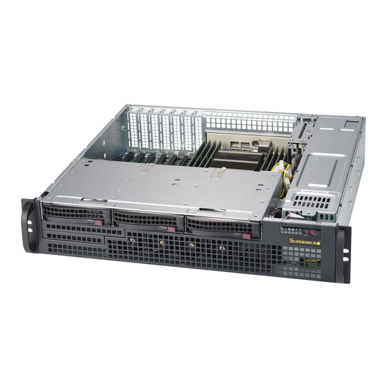
- Page 3 SC825M(B) chassis. Instal- lation and maintenance should be performed by experienced technicians only. Supermicro’s SC825M(B) 2U chassis is a short-depth chassis with a unique and highly-optimized design. The chassis is equipped with a redundant 700W or 800W high-efficiency power supply for superb power savings.
- Page 4 SC825M(B) Chassis Manual Manual Organization Chapter 1: Introduction The first chapter provides a checklist of the main components included with this chassis. This chapter also includes contact information. Chapter 2: Warning Statements for AC Systems This chapter lists warnings, precautions, and system safety. You should thoroughly familiarize yourself with this chapter for a general overview of safety precautions that should be followed before installing and servicing this chassis.
- Page 5 Preface Appendix A: Power Supply Specifications Appendix B: BPN-SAS-825MTQ Backplane Specifications Appendix C: BPN-SAS3-825MTQ Backplane Specifications...
-
Page 6: Table Of Contents
Chapter 1 Introduction Overview ......................1-1 Shipping List ....................1-1 Part Numbers ..................... 1-1 Contacting Supermicro ..................1-2 Returning Merchandise for Service..............1-3 Chapter 2 Standardized Warning Statements for AC Systems About Standardized Warning Statements ............2-1 Warning Definition ................... 2-1 Installation Instructions .................. - Page 7 Preface Chapter 4 System Interface Overview ......................4-1 Control Panel Buttons ..................4-2 Control Panel LEDs ..................4-2 Overheating ..................... 4-3 Drive Carrier LEDs ..................4-4 SAS/SATA Drives .................... 4-4 Power Supply LEDs ..................4-4 Chapter 5 Chassis Setup and Maintenance Overview ......................
- Page 8 SC825M(B) Chassis Manual Ambient Operating Temperature ..............6-3 Reduced Airflow ..................6-3 Mechanical Loading ................... 6-3 Circuit Overloading ..................6-3 Reliable Ground ....................6-3 Installing the System into a Rack ..............6-4 Identifying the Sections of the Rack Rails ............6-4 Locking Tabs ....................
-
Page 9: Chapter 1 Introduction
(Includes dummy (Front) cover) Optional DVD and 3x SAS3 SC825MBTQC- 4x FH 800W USB/COM port / SATA R802WB 3x LP Redundant (Includes dummy (Front) cover) Note: A complete list of safety warnings is provided on the Supermicro website at http://www.supermicro.com/about/policies/safety_information.cfm... -
Page 10: Contacting Supermicro
Super Micro Computer, Inc. 980 Rock Ave. San Jose, CA 95131 U.S.A. Tel: +1 (408) 503-8000 Fax: +1 (408) 503-8008 Email: marketing@supermicro.com (General Information) support@supermicro.com (Technical Support) Website: www.supermicro.com Europe Address: Super Micro Computer B.V. Het Sterrenbeeld 28, 5215 ML... -
Page 11: Returning Merchandise For Service
(http://www.super- micro.com/support/rma/). Whenever possible, repack the chassis in the original Supermicro carton, using the original packaging material. If these are no longer available, be sure to pack the chassis securely, using packaging material to surround the chassis so that it does not shift within the carton and become damaged during shipping. - Page 12 SC825M(B) Chassis Manual Notes...
-
Page 13: Chapter 2 Standardized Warning Statements For Ac Systems
The following statements are industry standard warnings, provided to warn the user of situations which have the potential for bodily injury. Should you have questions or experience difficulty, contact Supermicro's Technical Support department for assistance. Only certified technicians should attempt to install or configure components. - Page 14 SC825MB Chassis Manual Warnung WICHTIGE SICHERHEITSHINWEISE Dieses Warnsymbol bedeutet Gefahr. Sie befinden sich in einer Situation, die zu Verletzungen führen kann. Machen Sie sich vor der Arbeit mit Geräten mit den Gefahren elektrischer Schaltungen und den üblichen Verfahren zur Vorbeugung vor Unfällen vertraut.
- Page 15 Warning Statements for AC Systems جسذٌة اصابة ًتتسبب ف حالة ٌوكي أى ًاًك ف خطز ًٌٌع هذا الزهز !تحذٌز الذوائز بالوخاطز الٌاجوة عي ي على علن ، ك هعذات تعول على أي قبل أى الكهزبائٍة حىادث أي وقىع وٌع ل الىقائٍة...
-
Page 16: Installation Instructions
SC825MB Chassis Manual Installation Instructions Warning! Read the installation instructions before connecting the system to the power source. 設置手順書 システムを電源に接続する前に、 設置手順書をお読み下さい。 警告 将此系统连接电源前,请先阅读安装说明。 警告 將系統與電源連接前,請先閱讀安裝說明。 Warnung Vor dem Anschließen des Systems an die Stromquelle die Installationsanweisungen lesen. ¡Advertencia! Lea las instrucciones de instalación antes de conectar el sistema a la red de alimentación. -
Page 17: Circuit Breaker
Chapter 2: Warning Statements for AC Systems Circuit Breaker Warning! This product relies on the building's installation for short-circuit (overcurrent) protection. Ensure that the protective device is rated not greater than: 250 V, 20 A. サーキッ ト ・ ブレーカー この製品は、 短絡 (過電流) 保護装置がある建物での設置を前提としています。 保護装置の定格が250 V、... -
Page 18: Power Disconnection Warning
SC825MB Chassis Manual 경고! 이 제품은 전원의 단락(과전류)방지에 대해서 전적으로 건물의 관련 설비에 의존합니다. 보호장치의 정격이 반드시 250V(볼트), 20A(암페어)를 초과하지 않도록 해야 합니다. Waarschuwing Dit product is afhankelijk van de kortsluitbeveiliging (overspanning) van uw electrische installatie. Controleer of het beveiligde aparaat niet groter gedimensioneerd is dan 220V, 20A. - Page 19 Chapter 2: Warning Statements for AC Systems ¡Advertencia! El sistema debe ser disconnected de todas las fuentes de energía y del cable eléctrico quitado de los módulos de fuente de alimentación antes de tener acceso el interior del chasis para instalar o para quitar componentes de sistema. Attention Le système doit être débranché...
-
Page 20: Equipment Installation
SC825MB Chassis Manual Equipment Installation Warning! Only trained and qualified personnel should be allowed to install, replace, or service this equipment. 機器の設置 トレーニングを受け認定された人だけがこの装置の設置、 交換、 またはサービスを許可 されています。 警告 只有经过培训且具有资格的人员才能进行此设备的安装、更换和维修。 警告 只有經過受訓且具資格人員才可安裝、更換與維修此設備。 Warnung Das Installieren, Ersetzen oder Bedienen dieser Ausrüstung sollte nur geschultem, qualifiziertem Personal gestattet werden. -
Page 21: Restricted Area
Chapter 2: Warning Statements for AC Systems Waarschuwing Deze apparatuur mag alleen worden geïnstalleerd, vervangen of hersteld door geschoold en gekwalificeerd personeel. Restricted Area Warning! This unit is intended for installation in restricted access areas. A restricted access area can be accessed only through the use of a special tool, lock and key, or other means of security. -
Page 22: Battery Handling
SC825MB Chassis Manual אזור עם גישה מוגבלת !אזהרה יש להתקין את היחידה באזורים שיש בהם הגבלת גישה. הגישה ניתנת בעזרת .)'כלי אבטחה בלבד (מפתח, מנעול וכד محظورة مناطق ٍنتركُبها ف هذه انىحذة تخصيص تم ،أداة خاصت من خالل استخذاو فقط محظورة... - Page 23 Chapter 2: Warning Statements for AC Systems Warnung Bei Einsetzen einer falschen Batterie besteht Explosionsgefahr. Ersetzen Sie die Batterie nur durch den gleichen oder vom Hersteller empfohlenen Batterietyp. Entsorgen Sie die benutzten Batterien nach den Anweisungen des Herstellers. Attention Danger d'explosion si la pile n'est pas remplacée correctement. Ne la remplacer que par une pile de type semblable ou équivalent, recommandée par le fabricant.
-
Page 24: Redundant Power Supplies
SC825MB Chassis Manual Redundant Power Supplies Warning! This unit might have more than one power supply connection. All connections must be removed to de-energize the unit. 冗長電源装置 このユニッ トは複数の電源装置が接続されている場合があります。 ユニッ トの電源を切るためには、 すべての接続を取り外さなければなりません。 警告 此部件连接的电源可能不止一个,必须将所有电源断开才能停止给该部件供电。 警告 此裝置連接的電源可能不只一個,必須切斷所有電源才能停止對該裝置的供電。 Warnung Dieses Gerät kann mehr als eine Stromzufuhr haben. Um sicherzustellen, dass der Einheit kein trom zugeführt wird, müssen alle Verbindungen entfernt werden. -
Page 25: Backplane Voltage
Chapter 2: Warning Statements for AC Systems امداد الطاقة بوحدات عدة اتصاالت جهاز ال يكون لهذا قد الكهرباء عن وحدة ال لعسل كافة االتصاالت يجب إزالة 경고! 이 장치에는 한 개 이상의 전원 공급 단자가 연결되어 있을 수 있습니다. 이 장치에 전원을... -
Page 26: Comply With Local And National Electrical Codes
SC825MB Chassis Manual מתח בפנל האחורי !הרה אז קיימת סכנת מתח בפנל האחורי בזמן תפעול המערכת. יש להיזהר במהלך .העבודה اللىحة أوالطاقة المىجىدة على التيار الكهزبائي مه خطز هناك هذا الجهاس خدمة كه حذرا عند يعمل النظام عندما يكىن 경고! 시스템이... -
Page 27: Product Disposal
Chapter 2: Warning Statements for AC Systems Attention L'équipement doit être installé conformément aux normes électriques nationales et locales. תיאום חוקי החשמל הארצי !אזהרה הציוד חייבת להיות תואמת לחוקי החשמל המקומיים והארציים התקנת المتعلقة المحلية والىطىية قىاويه يجب أن يمتثل لل الكهربائية... -
Page 28: Hot Swap Fan Warning
SC825MB Chassis Manual Attention La mise au rebut ou le recyclage de ce produit sont généralement soumis à des lois et/ou directives de respect de l'environnement. Renseignez-vous auprès de l'organisme compétent. סילוק המוצר !אזהרה .חוקי המדינה סילוק סופי של מוצר זה חייב להיות בהתאם להנחיות ו القىانين... - Page 29 Chapter 2: Warning Statements for AC Systems Warnung Gefährlich Bewegende Teile. Von den bewegenden Lüfterblätter fern halten. Die Lüfter drehen sich u. U. noch, wenn die Lüfterbaugruppe aus dem Chassis genommen wird. Halten Sie Finger, Schraubendreher und andere Gegenstände von den Öffnungen des Lüftergehäuses entfernt. ¡Advertencia! Riesgo de piezas móviles.
-
Page 30: Power Cable And Ac Adapter
Electrical Appliance and Material Safety Law prohibits the use of UL or CSA -certified cables (that have UL/CSA shown on the code) for any other electrical devices than products designated by Supermicro only. 電源コードとACアダプター 製品を設置する場合、 提供または指定された接続ケーブル、 電源コードとACアダプター... - Page 31 Appareils électroménagers et de loi sur la sécurité Matériel interdit l'utilisation de UL ou CSA câbles certifiés qui ont UL ou CSA indiqué sur le code pour tous les autres appareils électriques que les produits désignés par Supermicro seulement.
- Page 32 SC825MB Chassis Manual Notes 2-20...
-
Page 33: Chapter 3 Chassis Components
Each SC825M(B) chassis comes with a backplane that supports SAS(3)/SATA hard disk drives. For details, see the appendix at the end of this manual and our website, http://www.supermicro.com. Power Supply Each SC825M(B) chassis includes two high-efficiency power supplies rated at 700... -
Page 34: Front Interface
Supermicro Authorized Distributors/ System Integrators/Resellers. A list of Supermicro Authorized Distributors/System Integrators/Reseller can be found at: http://www.supermicro.com. Click the Where to Buy link. -
Page 35: Chapter 4 System Interface
Chapter 4: System Interface Chapter 4 System Interface Overview This chassis includes LEDs on the control panel and drive carriers that indicate the activity and health of specific components. Figure 4-1. SC825MTQ-R700LPB/UB Figure 4-2. SC825MBTQC-R802LPB/WB... -
Page 36: Control Panel Buttons
SC825M(B) Chassis Manual Control Panel Buttons The chassis includes two push-buttons that control power to the system. Reset: The reset button is used to reboot the system. Power: The main power switch is used to apply or remove power from the power supply to the server system. -
Page 37: Overheating
There are several possible responses if the system overheats. Overheat Temperature Setting Some backplanes allow the overheat temperature to be set at 45, 50, or 55 by changing a jumper setting. For more information, consult the backplane user manual at www.supermicro.com. (Click Support, then the Manuals link.) -
Page 38: Drive Carrier Leds
SC825M(B) Chassis Manual Responses If the server overheats: 1. Use the LEDs to determine the nature of the overheating condition. 2. Confirm that the chassis covers are installed properly. 3. Check the routing of the cables and make sure all fans are present and oper- ating normally. -
Page 39: Chapter 5 Chassis Setup And Maintenance
Chapter 5: Chassis Setup and Maintenance Chapter 5 Chassis Setup and Maintenance Overview This chapter covers the steps required to install components and perform mainte- nance on the chassis. The only tools required are a Phillips screwdriver and, for a few tasks, a hex wrench. -
Page 40: Removing The Chassis Cover
SC825M(B) Chassis Manual Removing the Chassis Cover Remove this Screw Remove this Screw Figure 5-1. Removing the Chassis Cover Removing the Chassis Cover: 1. Power down the system and remove the power cord from the rear of the power supply as described in Section 5-2. 2. -
Page 41: Installing The Hard Drives
Chapter 5: Chassis Setup and Maintenance Installing the Hard Drives Figure 5-2. Removing Hard Drive Carriers The SC825M(B) features three hot-swappable hard drives that can be removed from the chassis without powering down the system. Removing the Hard Drives from the Chassis 1. - Page 42 SC825M(B) Chassis Manual Dummy Drive Drive Carrier Figure 5-3. Hard Drive Carrier The hard drives are mounted in hard drive carriers to simplify their installation and removal from the chassis. These carriers also help promote proper airflow for the drive bays. Caution: Except for short periods of time (while swapping hard drives), do not oper- ate the server with the hard drive bays empty.
- Page 43 Chapter 5: Chassis Setup and Maintenance SAS/SATA Hard Drive Figure 5-5. Installing a Hard Drive 3. Install a new drive into the carrier with the printed circuit board side facing down so that the mounting holes align with those in the carrier. 4.
-
Page 44: Installing The Rear 2.5" Hard Drive Cage (Sc825Mb Only)
SC825M(B) Chassis Manual Installing the Rear 2.5" Hard Drive Cage (SC825MB Only) The SC825MB model chassis supports an optional hard drive cage for two additional 2.5" hot-swappable hard drives. The hard drive cage installs in the rear of the chassis next to the power supply. Once the hard drive cage has been installed, the 2.5"... - Page 45 Chapter 5: Chassis Setup and Maintenance Figure 5-7. Installing the Rear 2.5" Hard Drive Cage Figure 5-8. Securing the Rear Hard Drive Cage to the Chassis 6. Secure the top of the hard drive cage to the chassis frame with two screws, fastened at the upper edge of the hard drive cage above the opening of the hard drive cage.
-
Page 46: Installing The Rear Drives Into Carriers (Sc825Mb Only)
SC825M(B) Chassis Manual Installing the Rear Drives Into Carriers (SC825MB Only) Figure 5-8. Removing the Dummy Drive from the Drive Carrier Installing a Hard Drive into a 2.5" Rear Drive Carrier 1. Insert a hard drive into the carrier with the PCB side facing down and the con- nector end toward the rear of the carrier. -
Page 47: Installing The Motherboard
Chapter 5: Chassis Setup and Maintenance Installing the Motherboard This section describes how to install the motherboard to the chassis. The hard drive housing and the metal bracket that holds the DVD and USB com port (or dummy covers) must be removed. I/O Shield Figure 5-10. -
Page 48: Hard Drive Housing And Dvd Drive Removal
SC825M(B) Chassis Manual Hard Drive Housing Figure 5-11. Hard Drive Housing Screws Hard Drive Housing and DVD Drive Removal Before installing the motherboard, you must remove the hard drive tray housing and the DVD drive. Removing the Hard Drive Housing 1. - Page 49 Chapter 5: Chassis Setup and Maintenance The DVD drive and the USB/COM port tray attach to the DVD drive bracket. For the 825MBTQC chassis model, the DVD drive and USB/COM port are not present (dummy covers are used). They are removed as a unit. Removing the DVD Drive Bracket 1.
-
Page 50: Permanent And Optional Standoffs
Flat head Round head Round head Pan head 6-32 x 5 mm 2.6 x 5 mm 6-32 x 5 mm 3 x 5 mm SC825M(B) Chassis Manual [0.197] [0.197] [0.197] [0.197] RAIL Permanent and Optional Standoffs Standoffs prevent short circuits by securing space between the motherboard and the chassis surface. -
Page 51: Installing Expansion Cards
Chapter 5: Chassis Setup and Maintenance Installing Expansion Cards The SC825M(B) chassis include slots for expansion cards. The number of slots varies depending upon the chassis model and the configuration of the system. See below for information specific to each chassis model. The motherboard must be installed before expansion cards. -
Page 52: Expansion Card Setup In Uio/Wio Model Chassis
SC825M(B) Chassis Manual Expansion Card Setup in UIO/WIO Model Chassis The configuration of the expansion cards in UIO/WIO models will vary, depending upon if a Universal I/O card or WIO card is used: With a UIO card: Up to three full-height, half-length I/O may be used Up to three low-profile PCI slots may be used. - Page 53 Chapter 5: Chassis Setup and Maintenance Figure 5-17. Removing the Retention Bracket (WIO Chassis Shown) 5. Remove the screw and the retention bracket securing the right side of the full height PCI slot covers (A) (see Figure 5-17). For UIO chassis (not shown), rotate the latch instead.
-
Page 54: Installing The Air Shroud
SC825M(B) Chassis Manual Installing the Air Shroud Air Shroud Perforations Figure 5-18. Air Shroud Air shrouds concentrate airflow to maximize fan efficiency. The air shroud does not require screws to install. Installing the Air Shroud 1. Power down the system and remove the power cord from the back of the power supply module as described in Section 5-2. -
Page 55: Checking The System Airflow
Chapter 5: Chassis Setup and Maintenance Checking the System Airflow Proper airflow allows the chassis to keep the server components cooled and prevent damage. Use the following steps to check airflow after setup and in the unlikely event the chassis needs to be serviced. Checking the Server's Air Flow •... -
Page 56: 5-10 System Fans
SC825M(B) Chassis Manual 5-10 System Fans The 825M(B) chassis includes four fans for cooling and air circulation. A dummy fan is included as a place holder. System Fans Rubber Fan Feet Dummy Fan Figure 5-19. System Fan and Dummy Fan in Fan Tray Note: The 825M(B) chassis includes four pre-installed fans. - Page 57 Chapter 5: Chassis Setup and Maintenance Figure 5-20. Placing the System Fans 5. Place the new fan into the vacant space in the housing while making sure the arrows on the top of the fan (indicating air direction) point in the same direction as the arrows on the other fans.
- Page 58 SC825M(B) Chassis Manual 5. Remove the metal bracket by unscrewing the 4 screws from the bottom side of chassis (see Figure 5-21). 6. Install the removed fan holder pins at the new location, using the supplied hex wrench to tighten it (see circled locations in Figure 5-22). 7.
-
Page 59: 5-11 Power Supply
Power Supply Replacement The chassis includes a redundant power supply. Power supplies can be replaced without powering down the system. Replacement units can be ordered directly from Supermicro (see contact information in Chapter 1). Release Tab Figure 5-23. Removing the Power Supply Replacing the Power Supply 1. -
Page 60: Replacing The Power Distributor
SC825M(B) Chassis Manual Figure 5-24. Replacing the Power Distributor Replacing the Power Distributor The power distributor provides failover and power supply redundancy. In the unlikely event you must replace the power distributor, do the following Replacing the Power Distributor 1. Power down the system and remove the power cord from the back of the power supply module as described in Section 5-2. -
Page 61: 5-12 Dvd Drive And Usb/Com Port
4. Reinstall the bracket to the chassis and reconnect the cables to the motherboard and backplane. 5-13 Optional Front Bezel The SC825M(B) chassis supports an optional full-face locking front bezel for added security. To order it, visit the Supermicro website at www.supermicro.com and click the Where to Buy link. Reference part number MCP-210-82502-0B. - Page 62 SC825M(B) Chassis Manual Notes 5-24...
-
Page 63: Chapter 6 Rack Installation
Chapter 6: Rack Installation Chapter 6 Rack Installation This chapter provides instructions for preparing and mounting your chassis in a rack. Unpacking the System You should inspect the box the chassis was shipped in and note if it was damaged in any way. -
Page 64: Warnings And Precautions
SC825M(B) Chassis Manual Warnings and Precautions Rack Precautions • Ensure that the leveling jacks on the bottom of the rack are fully extended to the floor with the full weight of the rack resting on them. • In single rack installations, stabilizers should be attached to the rack. •... -
Page 65: Rack Mounting Considerations
Chapter 6: Rack Installation Rack Mounting Considerations Ambient Operating Temperature If installed in a closed or multi-unit rack assembly, the ambient operating tempera- ture of the rack environment may be greater than the ambient temperature of the room. Therefore, consideration should be given to installing the equipment in an environment compatible with the manufacturer’s maximum rated ambient tempera- ture (TMRA). -
Page 66: Installing The System Into A Rack
SC825M(B) Chassis Manual Installing the System into a Rack This section provides information on installing the chassis into a rack unit with the rails provided. There are a variety of rack units on the market, which may mean that the assembly procedure will differ slightly from the instructions provided. You should also refer to the installation instructions that came with the rack unit you are using. -
Page 67: Locking Tabs
Chapter 6: Rack Installation Locking Tabs Each inner rail has a locking tab. This tab locks the chassis into place when installed and pushed fully into the rack. These tabs also lock the chassis in place when fully extended from the rack. This prevents the server from coming completely out of the rack when when the chassis is pulled out for servicing. -
Page 68: Installing The Inner Rails On The Chassis
SC825M(B) Chassis Manual Installing The Inner Rails on the Chassis Installing the Inner Rails 1. Confirm that the left and right inner rails have been correctly identified. Place the inner rail firmly against the side of the chassis, aligning the hooks on the side of the chassis with the holes in the inner rail. -
Page 69: Installing The Outer Rails On The Rack
Chapter 6: Rack Installation L-min=676.00(26.61")(outer rail) 21D01 Figure 6-5. Extending and Releasing the Outer Rails Installing the Outer Rails on the Rack Installing the Outer Rails 1. Press upward on the locking tab at the rear end of the middle rail. 2. -
Page 70: Standard Chassis Installation
SC825M(B) Chassis Manual Standard Chassis Installation Stability hazard. The rack stabilizing mechanism must be in place, or the rack must be bolted to the floor before you slide the unit out for servicing. Failure to stabilize the rack can cause the rack to tip over. Installing the Chassis into a Rack 1. - Page 71 Chapter 6: Rack Installation Figure 6-8. Installing the Chassis into a Rack Figure 6-8. Completed Chassis Installation...
- Page 72 SC825M(B) Chassis Manual Notes 6-10...
-
Page 73: Appendix A Sc825M Power Supply Specifications
Appendix A: Power Supply Specifications Appendix A SC825M(B) Power Supply Specifications This appendix lists power supply specifications for your chassis. SC825MTQ-R700LPB and SC825MTQ-R700UB 700W (Redundant) MFR Part # PWS-702A-1R 100 - 240V Rated AC Voltage 60 - 50Hz 10 - 4 Amp +5V standby 4 Amp +12V... - Page 74 SC825M(B) Chassis Manual Notes...
-
Page 75: Appendix B Bpn-Sas-825Mtq Backplane Specifications
Appendix B: BPN-SAS-825MTQ Backplane Specifications Appendix B BPN-SAS-825MTQ Backplane Specifications This chapter offers guidelines for personal and equipment safety, and notes about the BPN-SAS-825MTQ version documented in this manual. B-1 ESD Safety Guidelines Electrostatic Discharge (ESD) can damage electronic com ponents. To prevent damage to your system, it is important to handle it very carefully. - Page 76 This manual reflects BPN-SAS-825MTQ, Revision 1.01, the most current release available at the time of publication. Refer to the Supermicro website at www.supermicro.com for the latest updates, compatible parts and supported...
- Page 77 Appendix B: BPN-SAS-825MTQ Backplane Specifications B-4 Rear Connector Locations The following connectors are on the side of the backplane that faces the rear of the chassis. They are marked by silkscreen labels. JP51 SIDEBAND LED TEST JP46 +12V +12V UPGRADE +12V RESET J29 UPER...
- Page 78 SC825M(B) Chassis Manual B-5 Rear Connector and Pin Definitions 1. Main Power Connector Backplane Main Power The 4-pin connector, designated JP10, pro- 4-Pin Connector vides power to the backplane. See the table Pin# Definition on the right for pin definitions. +12V 2 and 3 Ground...
- Page 79 Appendix B: BPN-SAS-825MTQ Backplane Specifications 6. MG9071 Upgrade Header The upgrade header is designated JP46 and is used for manufacturing purposes only. 7. - 9. SAS Ports The SAS ports are used to connect the SAS drive cables. The three ports are designated #0 - #2 and are compatible with SAS/SATA drives.
- Page 80 SC825M(B) Chassis Manual B-6 Rear Jumper Locations and Pin Definitions JP51 SIDEBAND LED TEST JP46 +12V +12V UPGRADE +12V RESET J29 UPER BPN-SAS-825MTQ REV 1.02 Figure B-2. BPN-SAS-825MTQ Rear Jumpers Explanation of Jumpers Connector Pins To modify the operation of the backplane, jumpers can be used to choose between optional settings.
- Page 81 Appendix B: BPN-SAS-825MTQ Backplane Specifications B-7 Front Connectors and LED Indicators Front Connector Locations BAR CODE SAS #0 SAS #1 SAS #2 SAS#0 SAS#1 SAS#2 Figure B-3. BPN-SAS-825MTQ Front View Front Connector/LED Indicator Descriptions Front SAS Connectors Rear SAS Drive Number Connector SAS#0 SAS/SATA HHD #0...
- Page 82 SC825M(B) Chassis Manual Notes...
-
Page 83: Appendix C Bpn-Sas3-825Mtq Backplane Specifications
The BPN-SAS3-825MTQ has been designed to utilize the most up-to-date technology available, providing your system with reliable, high-quality performance. This manual reflects BPN-SAS3-825MTQ revision 1.02, the most current release available at the time of publication. Refer to www.supermicro.com for the latest updates, compatible parts and supported configurations. - Page 84 SC825M(B) Chassis Manual C-4 Rear Connector Locations The following connectors are on the side of the backplane that faces the rear of the chassis. They are marked by silkscreen labels. JP51 SIDEBAND LED TEST JP46 +12V UPGRADE +12V +12V RESET J29 UPER BPN-SAS-825MTQ REV 1.02...
- Page 85 Appendix C: BPN-SAS3-825MTQ Backplane Specifications C-5 Rear Connector and Pin Definitions 1. Main Power Connector Backplane Main Power The 4-pin connector, designated JP10, pro- 4-Pin Connector vides power to the backplane. Pin# Definition +12V 2 and 3 Ground Sideband Connector Pin # Definition Pin # Definition...
- Page 86 SC825M(B) Chassis Manual C-6 Rear Jumper Locations and Pin Definitions JP51 SIDEBAND LED TEST JP46 +12V +12V UPGRADE +12V RESET J29 UPER BPN-SAS-825MTQ REV 1.02 Figure C-2. BPN-SAS3-825MTQ Rear Jumpers Explanation of Jumpers Connector Pins To modify the operation of the backplane, jumpers can be used to choose between optional settings.
- Page 87 Appendix C: BPN-SAS3-825MTQ Backplane Specifications C-7 Front Connectors and LED Indicators Front Connector Locations BAR CODE SAS #0 SAS #1 SAS #2 SAS#0 SAS#1 SAS#2 Figure C-3. BPN-SAS3-825MTQ Front View Front Connector/LED Indicator Descriptions Front SAS Connectors Rear Connector SAS Drive Number SAS#0 SAS/SATA HHD #0 SAS#1...
- Page 88 SC825M(B) Chassis Manual Disclaimer (cont.) The products sold by Supermicro are not intended for and will not be used in life sup- port systems, medical equipment, nuclear facilities or systems, aircraft, aircraft devices, aircraft/emergency communication devices or other critical systems whose failure to per- form be reasonably expected to result in significant injury or loss of life or catastrophic property damage.
Need help?
Do you have a question about the SC825M Series and is the answer not in the manual?
Questions and answers