Sign In
Upload
Manuals
Brands
Supermicro Manuals
Chassis
SC745S2-800VB
User Manuals: Supermicro SC745S2-800VB Chassis
Manuals and User Guides for Supermicro SC745S2-800VB Chassis. We have
1
Supermicro SC745S2-800VB Chassis manual available for free PDF download: User Manual
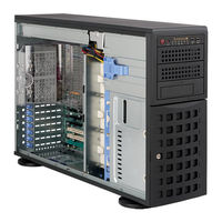
Supermicro SC745S2-800VB User Manual (104 pages)
SC745 CHASSIS Series
Brand:
Supermicro
| Category:
Chassis
| Size: 13 MB
Table of Contents
Table of Contents
7
Preface
5
Manual Organization
5
Table of Contents
7
Chapter 1: Introduction
11
Overview
11
Shipping List
11
Part Numbers
11
Chassis Features
12
Cpu
12
Hard Drives
12
I/O Expansion Slots
12
Other Features
12
Peripheral Drives
12
Contacting Supermicro
13
Chapter 2: System Safety
15
Overview
15
Warnings and Precautions
15
Preparing for Setup
15
Electrical Safety Precautions
16
General Safety Precautions
17
System Safety
17
Chapter 3: Chassis Components
19
Overview
19
Components
19
Backplane
19
Chassis
19
Fans
19
Mounting Rails (Optional)
19
Air Shroud
20
Power Supply
20
Where to Get Replacement Components
20
Chapter 4: System Interface
21
Overview
21
Control Panel Buttons
22
Control Panel Leds
22
Drive Carrier Leds
23
SAS/SATA Drives
23
SCSI Drives
24
Chapter 5: Chassis Setup and Maintenance
25
Overview
25
Installation Steps
25
General Maintenance
25
Installation Step 1: Remove the Chassis Cover
26
To Remove the Chassis Cover
26
To Replace the Chassis Cover
26
The Front Cover
27
To Remove the Front Cover
27
Installation Step 2: Confi Gure the Storage Module
28
Tower or Rack Confi Guration
28
To Rotate the Storage Module for Rack Mounting
29
Adding Drives to the Storage Module
30
To Add up to Three Hard Drives to the Drive Trays
31
To Add up to Three Peripheral Drives (DVD-ROM, CD-ROM, Fl Oppy Drive, Etc.) to the Drive Trays
33
To Add Fi Ve Hard Drives Using a Supermicro Mobile Rack
35
Installation Step 2: Install Hard Drives
37
To Install Hard Drives to the Chassis
37
Installation Step 3: Install the Motherboard
39
I/O Slot Shield
39
To Install the I/O Shield
39
Permanent and Optional Standoffs
40
To Install the Motherboard
41
Power Supply Connections
42
Add-On Card/Expansion Slot Setup
43
To Install Add-On and Expansion Cards
43
Installation Step 4: Install the Air Shroud
45
To Install the Air Shroud
45
Installation Complete
46
To Check the Server's Air Fl Ow
46
System Fans
47
To Replace a System Fan
47
To Replace a Rear Chassis Fan
48
Power Supply
49
Power Supply Failure
49
Chapter 6: Rack Installation
51
Overview
51
Unpacking the System
51
Preparing for Setup
51
Choosing a Setup Location
51
Ambient Operating Temperature
52
General Server Precautions
52
Rack Mounting Considerations
52
Rack Precautions
52
Circuit Overloading
53
Mechanical Loading
53
Reduced Airfl Ow
53
Reliable Ground
53
Rack Mounting Instructions
54
Removing the Chassis Cover and Feet
54
To Remove the Chassis Feet
55
To Remove the Chassis Top Cover
55
Identifying the Sections of the Rack Rails
56
To Install the Chassis Handles and Inner Rails
57
To Install the Outer Rails to the Rack
58
To Install the Chassis into a Rack
59
Tower Mounting Instructions
60
To Install the Chassis Cover
60
To Place Chassis Feet
61
Appendices
63
Appendix A: SC745 Chassis Cables
65
A-1 Overview
65
Cables Included with SC745TQ Chassis (SAS/SATA
65
Cables Included with SC745S Chassis (SCSI
65
A-2 Cables Included with SC745TQ Chassis (SAS/SATA)
65
A-3 Cables Included with SC745S Chassis (SCSI)
65
A-4 Compatible Cables
66
Alternate SAS/SATA Cables
66
Extending Power Cables
67
Front Panel to the Motherboard
67
Appendix B: SC745 Power Supply Specifi Cations
69
Table of Contents
73
An Important Note to Users
75
Chapter 1: Safety Guidelines
75
ESD Safety Guidelines
75
General Safety Guidelines
75
Chapter 2: Jumper Settings and Pin Defi Nitions
77
Front Connectors and Jumpers
77
Front Connector and Pin Defi Nitions
78
Front Jumper Locations and Pin Defi Nitions
80
Rear Connectors and LED Indicators
82
Safety Information and Technical Specifications
86
Safety Guidelines
87
Safety Information and Technical Specifications
87
Front Connectors and Jumpers
88
A-2. Front Connectors
88
A-3. Front Connector Pin Definitions
89
A-6. Front/Rear SAS Connectors and Locations
91
B-2. Rear Connector/Led Indicator Descriptions
93
B-3. the AMI MG9072 SES-2 Controller (SCSI Enclosure Services-2) LED Indicators
94
Packing List
97
Technical Specifications
98
Jumper Settings
99
Installation Procedures
101
Jumper Settings and Pin Definitions
88
Advertisement
Advertisement
Related Products
Supermicro SC745S2-R800B
Supermicro SC745TQ-R800B
Supermicro SC745BTQ-R1K28B
Supermicro SC745BTQ-R1K28B-SQ
Supermicro SC745TQ-R1200B
Supermicro SC745TQ-1200B
Super Micro SC745TQ-R920B
Supermicro SC745BAC-R1K23B
Supermicro SC745BAC-R1K23B-SQ
Supermicro SC745BTQ-R920B
Supermicro Categories
Server
Motherboard
Computer Hardware
Chassis
Switch
More Supermicro Manuals
Login
Sign In
OR
Sign in with Facebook
Sign in with Google
Upload manual
Upload from disk
Upload from URL