Webasto Air Top Evo 3900 Workshop Manual
Hide thumbs
Also See for Air Top Evo 3900:
- Installation instructions manual (55 pages) ,
- Workshop manual (53 pages) ,
- Installation & operating instructions manual (16 pages)
Table of Contents
Advertisement
Advertisement
Table of Contents
Troubleshooting

Related Manuals for Webasto Air Top Evo 3900


Summary of Contents for Webasto Air Top Evo 3900
- Page 1 Visit www.butlertechnik.com for more technical information & downloads. Luft-Heizgeräte 03/2003 Air heaters Workshop Manual Air Top Evo 3900 Air Top Evo 5500 Type Air Top Evo 3900/5500 B (Petrol) Type Air Top Evo 3900/5500 D (Diesel/PME) www.butlertechnik.com...
- Page 2 Only genuine Webasto parts may be used. See also Webasto air and water heaters accessories catalogue. NEVER try to install or repair Webasto heating or cooling systems if you have not completed a Webasto training course, you do not have the necessary technical skills and you do not have the technical documentation, tools and equipment available to ensure that you can complete the installation and repair work properly.
-
Page 3: Table Of Contents
Visit www.butlertechnik.com for more technical information & downloads. Air Top Evo 3900/5500 Table of Contents Table of Contents Introduction ................101 Contents and purpose. - Page 4 Table of Contents Air Top Evo 3900/5500 Function Tests ............... . 601 General .
- Page 5 Visit www.butlertechnik.com for more technical information & downloads. Air Top Evo 3900/5500 Table of Contents Repair ................901 General.
- Page 6 Air Top Evo 3900/5500 air heater without casing ....... . .
-
Page 7: Introduction
1.1.1 Use of the air heaters passages of the procedures. The Webasto Air Top Evo 3900 and Air Top Evo 5500 air 1.4.1 Statutory regulations governing installa- heaters are designed tion –... - Page 8 Visit www.butlertechnik.com for more technical information & downloads. Introduction Air Top Evo 3900/5500 2. / 5.3. (Part I) VEHICLE INSTALLATION REQUIRE- 2.5. / 5.3.5. (Part I) Combustion air inlet MENTS 2.5.1. / 5.3.5.1. (Part I) The air for the combustion 2.1.
-
Page 9: General Safety Information
They must be separated from the engine in such a way that in the event of an accident the fuel will not be ex- The Air Top Evo 3900 and Air Top Evo 5500 air heaters are pected to ignite. This does not apply to tractor units prepared for interior installation and sealing direct on the with an open driver’s seat. - Page 10 Webasto workshop. Webasto. The same applies if repairs are carried out incor- rectly or with the use of parts other than genuine spare Put the heater out of action by removing the fuse.
-
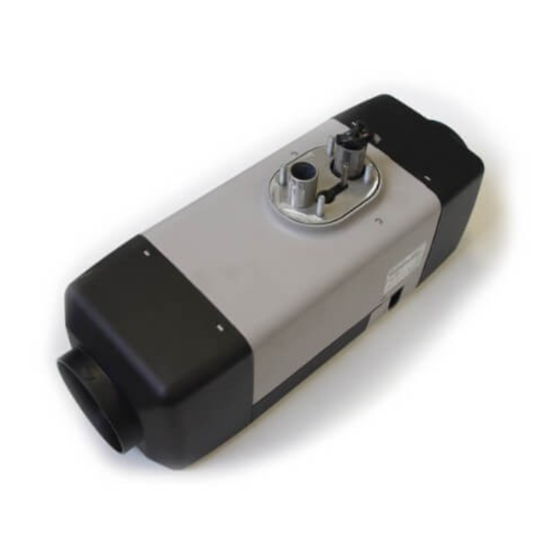
Page 11: Fig. 201 Air Top Evo 3900/5500 Air Heater
Visit www.butlertechnik.com for more technical information & downloads. Air Top Evo 3900/5500 General description General description The Air Top Evo 3900 and Air Top Evo 5500 air heaters are based on the evaporator principle and essentially consist of the following –... -
Page 12: Fig. 204 Heat Exchanger
Visit www.butlertechnik.com for more technical information & downloads. General description Air Top Evo 3900/5500 Heat exchanger The heat generated by the combustion process is trans- ferred to the air transported by the combustion and hot air blowers in the heat exchanger. -
Page 13: Fig. 208 Glow Plug / Flame Monitor
Visit www.butlertechnik.com for more technical information & downloads. Air Top Evo 3900/5500 General description Glow plug / Flame monitor Metering pump The glow plug also acts as a flame monitor. The metering pump is a combined transport, metering and The mixture of fuel and air is ignited by the glow plug when shut-off system for supplying fuel from the vehicle’s tank to... - Page 14 Visit www.butlertechnik.com for more technical information & downloads. General description Air Top Evo 3900/5500 Page for notes www.butlertechnik.com...
-
Page 15: Function Description
Operating modes of heater Set the control element to the required temperature. The Air Top Evo 3900 and Air Top Evo 5500 can be activated If the hot air temperature is lower than the nominal temper- with the heater controls rotary selector, combination timer ature the heater will start or MC04/05. -
Page 16: Heating Mode
3.8.1 System design Control mode The Air Top Evo 3900 Automatic AM Diesel and Air Top Evo 5500 Automatic AM Diesel variants offer the option of op- In the control mode the fan speed and the metering-pump erating up to 4 heaters in one system. Here Unit 1 is defined pumping quantity are dependent on the heating capacity. -
Page 17: Initial Installation/Initial Operation
Air Top Evo 3900/5500 Function Description Heater functions when installed in IMPORTANT The use of an Air Top Evo 3900 AM or Air Top Evo 5500 AM ADR vehicles system is not approved for dangerous goods transports (ADR)! NOTE 24V Only for Air Top Evo 3900/5500 D heaters that are installed in vehicles for transporting hazardous substances (ADR). -
Page 18: Fault Lock-Out
Visit www.butlertechnik.com for more technical information & downloads. Function Description Air Top Evo 3900/5500 3.10.1 Error monitoring 3.1.1.2. The exhaust system as well as the exhaust pipes shall be so directed or protected to avoid any danger to the load through heating or ignition. Parts... -
Page 19: Reset A Fault Lock-Out
Visit www.butlertechnik.com for more technical information & downloads. Air Top Evo 3900/5500 Function Description 3.10.2 Reset a fault lock-out The various fault statuses can be reset as follows. Fault lock-out: Switch off heater with heater control, wait at least 2 seconds and switch back on. - Page 20 Visit www.butlertechnik.com for more technical information & downloads. Function Description Air Top Evo 3900/5500 Page for notes www.butlertechnik.com...
-
Page 21: Fig. 401 Technical Data Of Air Top Evo 3900/5500
– Storage –40 °C - +85 °C Permissible combustion-air intake tem- –40 °C - +20 °C perature Adjustment range for interior tempera- Control +5 °C - +35 °C ture range Fig. 401 Technical data of Air Top Evo 3900/5500 www.butlertechnik.com... -
Page 22: Fig. 402 Setpoint Values For Resistance Values Of Components
423 ± 2 mm Width 148 ± 1 mm Height 162 ± 1 mm Heater weight 5.9 kg Fig. 401 Technical data of Air Top Evo 3900/5500 Setpoint values: 12 V 24 V Glow plug At 25 ºC No marking Green marking Test current: <... -
Page 23: Troubleshooting
This section describes how to identify and deal with errors fault: on the Air Top Evo 3900 and Air Top Evo 5500 heaters. • Corroded plugs If a fault occurs, an error code will be output in the display •... -
Page 24: Fig. 502 Error Symptoms During Function
Visit www.butlertechnik.com for more technical information & downloads. Troubleshooting Air Top Evo 3900/5500 Error symptoms during function in an emergency you can contact our technicians on our service hotline. The following table (Fig. 502) lists the possible error NOTE symptoms in the order in which they may occur during Every fault is indicated by the flashing LED on the control el- operation. -
Page 25: Fig. 503 Troubleshooting (Page 1 Of 2)
Visit www.butlertechnik.com for more technical information & downloads. Air Top Evo 3900/5500 Troubleshooting Error code output NOTE The error code is output if the heater is fitted with a control element after an error has occurred by the switch-on indica- If the heater is fitted with a combination timer, an error code tor/error code indicator flashing. -
Page 26: Fig. 503 Troubleshooting (Page 2 Of 2)
Visit www.butlertechnik.com for more technical information & downloads. Troubleshooting Air Top Evo 3900/5500 Error Error (group) Additional information during PC Troubleshooting code diagnostic F 07 Metering pump interrupt or 88 Break or short circuit to +Ub Check cables, replace metering pump... -
Page 27: Function Tests
– 3 MB of free memory on the hard disk 15 Combination timer – a free COM port (RS232C) or a free USB port – Optional: Internet connection (for software updates) – Webasto Thermo Test does not run under Windows 3.1 with Win32s www.butlertechnik.com... -
Page 28: Settings
Visit www.butlertechnik.com for more technical information & downloads. Function Tests Air Top Evo 3900/5500 Settings 6.3.1 Setting CO content The CO content in the emissions is set using the temperature selector on the control element. Activate any desired heating mode (Eco, Normal or Plus) in the process with the MC04/05 heater control. -
Page 29: Testing Individual Components
Webasto within the warranty period. [vol. %] Repair/replace component if necessary and put heater min. tolerance for operation [vol. %] into operation. max. tolerance for operation [vol. %] Repair/replace component. Only send defective component (not entire heater) to Webasto within warranty period. www.butlertechnik.com... -
Page 30: Burner Component
Visit www.butlertechnik.com for more technical information & downloads. Function Tests Air Top Evo 3900/5500 6.4.1 Burner component See Fig. 904, Item 33 and Item 7 Procedure Testing and Visual measuring equipment Burner Burner mechanically damaged? Visual inspection No blockages in the fuel... -
Page 31: Combustion And Hot Air Fan Component
Visit www.butlertechnik.com for more technical information & downloads. Air Top Evo 3900/5500 Function Tests 6.4.2 Combustion and hot air fan component See Fig. 903, Item 1 Procedure Testing and Visual measuring equipment Combustion and hot air mechanically damaged? Visual inspection –... - Page 32 Visit www.butlertechnik.com for more technical information & downloads. Function Tests Air Top Evo 3900/5500 Procedure Testing and Visual measuring Glow plug equipment Contacts detached? Visual inspection Cables damaged? Visual inspection Ceramic broken? Visual inspection Resistance outside 0.190 - 0.250 ohms (12 V) 0.740 - 0.940 ohms (24 V)?
-
Page 33: Drive Component
Visit www.butlertechnik.com for more technical information & downloads. Air Top Evo 3900/5500 Function Tests 6.4.4 Drive component See Fig. 903, Item 1 Procedure Testing and Visual measuring Drive unit equipment Externally damaged? Visual inspection Installation of component in unit => short circuit to metal parts (heat exchanger etc.)? -
Page 34: Fig. 601 Characteristic Resistance Values Of A Pt 2000 Overheating System In A
Visit www.butlertechnik.com for more technical information & downloads. Function Tests Air Top Evo 3900/5500 6.4.5 Overheating sensor component See Fig. 903, Item 8 If you conduct this resistance test with a digital multimeter, the overheating sensor must have the values shown in the following diagram: Temperature in °C... -
Page 35: Control Unit Component
Visit www.butlertechnik.com for more technical information & downloads. Air Top Evo 3900/5500 Function Tests 6.4.6 Control unit component See Fig. 701 and Fig. 903, Item 3 Procedure Testing and Visual measuring Control unit equipment Externally damaged? Visual inspection Conduct function –... -
Page 36: Heater Component
Visit www.butlertechnik.com for more technical information & downloads. Function Tests Air Top Evo 3900/5500 6.4.7 Heater component Description Procedure Testing and measuring Complete heater equipment Remove upper shell from heater and pull component connector off control unit PCB. Wire colours of... - Page 37 Visit www.butlertechnik.com for more technical information & downloads. Air Top Evo 3900/5500 Function Tests Description Procedure Testing and measuring equipment Check function on heater test bench Reading out control unit data: Burning hours, number of starts, errors Send printouts of diagnosis...
- Page 38 Visit www.butlertechnik.com for more technical information & downloads. Function Tests Air Top Evo 3900/5500 Description Procedure Testing and measuring equipment Reinstalling control unit in heater to be tested value Function test within tolerance? measurement Set CO value in permissible range with adjusting screw –...
-
Page 39: Fig. 701 Plug Assignment
Fig. 701 shows the plug assignment on the control unit. Fig. 709 shows the schematic connection of the combina- The Air Top Evo 3900 and Air Top Evo 5500 heater units can tion timer. be operated with the heater control (setpoint generator/ switch), a combination timer or the MC04/05 heater con- Fig. -
Page 40: Fig. 702 System Circuit Diagram 12V/24V With Control Element And Vehicle Blower
Visit www.butlertechnik.com for more technical information & downloads. 7 Circuit diagrams Air Top Evo 3900/5500 Fig. 702 System circuit diagram 12V/24V with control element and vehicle blower Fig. 703 System circuit diagram 24V ADR operation with control element www.butlertechnik.com... -
Page 41: Fig. 704 System Circuit Diagram 12V/24V With Combination Timer And Vehicle Blower
Visit www.butlertechnik.com for more technical information & downloads. Air Top Evo 3900/5500 7 Circuit diagrams Fig. 704 System circuit diagram 12V/24V with combination timer and vehicle blower Fig. 705 System circuit diagram (diesel) 12V/24V with combination timer and electrical battery isolation switch... -
Page 42: Fig. 706 System Circuit Diagram (Diesel) 12V/24V With Control Panel Mc04/05 And Vehicle Blower
7 Circuit diagrams Air Top Evo 3900/5500 Fig. 706 System circuit diagram (diesel) 12V/24V with Control Panel MC04/05 and vehicle blower Fig. 707 System wiring diagram Air Top Evo 3900 / 5500 AM “Master heater unit”, 12V/24V Diesel with controls www.butlertechnik.com... -
Page 43: Fig. 708 System Wiring Diagram Air Top Evo 3900 / 5500 Am "Slave Heater Unit", 12V/24V Diesel
Visit www.butlertechnik.com for more technical information & downloads. Air Top Evo 3900/5500 7 Circuit diagrams Fig. 708 System wiring diagram Air Top Evo 3900 / 5500 AM “Slave heater unit”, 12V/24V Diesel Combination timer 1531 black: Terminal 15 red: Terminal 30... -
Page 44: Fig. 710 Schematic Connection Of The Control Panel Mc04/05
W-Bus + Heater units Connection for wiring harness Webasto Thermo Test diagnosis Heater unit 1 Heater unit 2 Fig. 711 Connection diagram of Air Top Evo 3900/5500 AM (connection of combination timer 1531 and setpoint generator possible) www.butlertechnik.com... -
Page 45: Legend For Circuit Diagrams
Visit www.butlertechnik.com for more technical information & downloads. Air Top Evo 3900/5500 7 Circuit diagrams Legend for circuit diagrams Cable cross-sections Cable colours < 7.5 m 7.5 - 15 m blue brown 0.75 mm 1.0 mm yellow green 1.0 mm 1.5 mm... - Page 46 Visit www.butlertechnik.com for more technical information & downloads. 7 Circuit diagrams Air Top Evo 3900/5500 Page for notes www.butlertechnik.com...
-
Page 47: Work On The Heater
The service signal is output for 10 seconds during each heater unit start-up and can be re- set with the Webasto diagnosis by pulling the fuse or with This section describes the servicing work that can be carried "Delete fault“. -
Page 48: Fig. 801 Fuel Supply
Minimum internal diameter of the main section of hot air 0.00 0.20 line: 1.00 0.11 2.00 0.03 80 mm for the Air Top Evo 3900 Maximum fuel intake At max. perm. negative 90 mm for the Air Top Evo 5500 height pressure [bar] in the fuel S [m] tank The hot air hose must be secured at its connection points. -
Page 49: Fig. 802 Webasto Tank Connector
(for example Part No. 470 910), in which case it must be ensured that the return line continues almost to the bot- tom of the tank. If this is not the case Webasto fuel extractor (see Fig. 802, Fig. 803 or Fig. 804) may be used. -
Page 50: Fig. 805 Pipe/Hose Connections
Air Top Evo 3900/5500 8.6.2.2 Fuel lines Only steel, copper and plastic lines of plasticised, light and Air Top Evo 3900 / Air Top Evo 5500 12 V - petrol temperature-stabilised PA11 or PA12 (e.g. Mecanyl RWTL) DP2 metering pump (with damper) pursuant to DIN 73378 may be used for the fuel lines. -
Page 51: Fig. 807 Fuel Filter
8 Servicing work 8.6.4 Fuel filter ø 6,5 Only a Webasto filter, ident. no. 487 171, is allowed to be used if the fuel is expected to be contaminated. Install verti- cally if possible, however at least horizontally (check flow di- rection). -
Page 52: Fig. 810 Remove The Fastening Plate On The Fuse Holder
Visit www.butlertechnik.com for more technical information & downloads. 8 Servicing work Air Top Evo 3900/5500 Discharge direction al- most vertical 90° ± 10° Fig. 810 Remove the fastening plate on the fuse holder F = 10A 24V Fig. 809 Exhaust pipe ends, installation position... - Page 53 Visit www.butlertechnik.com for more technical information & downloads. Air Top Evo 3900/5500 8 Servicing work 8.6.8.3 Control element connection The wiring harness is prepared for connection to the control element. Simply pull on connector housing to unplug the connector (Fig. 813).
-
Page 54: Fig. 814 Installation Example For Heater In Recirculation Mode
Visit www.butlertechnik.com for more technical information & downloads. 8 Servicing work Air Top Evo 3900/5500 1 Control element 2 Heater 3 Metering pump 4 Fuel filter (accessory) 5 Tank connector 6 Exhaust silencer 7 Fuse Fig. 814 Installation example for heater in recirculation mode... -
Page 55: Heater, Removal And Installation
1. Place the heater with a new seal on the exhaust outlet in the installation position and secure it with 4 nuts and locking washers (use only genuine Webasto nuts). 2. Tighten the nuts to 6 +1 Nm. 3. Secure the connection for the combustion air inlet on the heater. - Page 56 Visit www.butlertechnik.com for more technical information & downloads. 8 Servicing work Air Top Evo 3900/5500 Page for notes www.butlertechnik.com...
-
Page 57: Fig. 901 External Temperature Sensor
General Any further dismantling will invalidate the warranty. Only The Air Top Evo 3900 or Air Top Evo 5500 heater can con- use the spare parts from the appropriate spare parts kits for trol the required temperature perfectly if its temperature assembling the heater. -
Page 58: Dismantling And Assembling
Visit www.butlertechnik.com for more technical information & downloads. 9 Repair Air Top Evo 3900/5500 Dismantling and assembling 9.2.1 Remove the casing parts 9.2.2.2 Top shell Place the top shell (2, Fig. 902) on the heater and secure 9.2.1.1 Cover for electrical connection it in the grooves in the bottom shell. -
Page 59: Fig. 902 Remove/Fit The Casing Parts
Visit www.butlertechnik.com for more technical information & downloads. Air Top Evo 3900/5500 9 Repair Cover, electrical connection Top shell Cover, hot air outlet Bottom shell Cover, hot air inlet Grill Insulators (4) Insulator positioning Widening Insulator of corner rib Fig. 902 Remove/fit the casing parts... -
Page 60: Change The Control Unit
Visit www.butlertechnik.com for more technical information & downloads. 9 Repair Air Top Evo 3900/5500 9.2.3 Change the control unit 9.2.5 Change combustion and hot air fan (drive unit) 9.2.3.1 Removal IMPORTANT 1. Remove heater (see 8.7.1.1). Only replace the drive unit (1, Fig. 903) with a drive unit with 2. -
Page 61: Fig. 207 Control Unit
Visit www.butlertechnik.com for more technical information & downloads. Air Top Evo 3900/5500 9 Repair Combustion and hot air fan (drive unit) Torx screw (8) Control unit Torx screw (2) Terminating resistor Flat seal Heat exchanger Overheating sensor Detail A Fig. 903 Change control unit, overheating sensor and combustion and hot air fan (drive unit) -
Page 62: Change Burner And Glow Plug/Flame Sensor
Visit www.butlertechnik.com for more technical information & downloads. 9 Repair Air Top Evo 3900/5500 9.2.6 Change burner and glow plug/flame 9.2.7 Change the combustion chamber and the sensor heat exchanger 9.2.6.1 Removal 9.2.7.1 Removal 1. Remove heater (see 8.7.1.1). 1. Remove heater (see 8.7.1.1). -
Page 63: Fig. 904 Change Burner, Glow Plug/Flame Sensor, Combustion Chamber And Heat Exchanger
Visit www.butlertechnik.com for more technical information & downloads. Air Top Evo 3900/5500 9 Repair Torx screw (4) Clamping bar Diesel burner Combustion chamber Round sealing ring Heat exchanger Petrol burner Glow plug/Flame monitor Retaining clip Fig. 904 Change burner, glow plug/flame sensor, combustion chamber and heat exchanger... - Page 64 Visit www.butlertechnik.com for more technical information & downloads. 9 Repair Air Top Evo 3900/5500 Page for notes www.butlertechnik.com...
-
Page 65: General
10 Packaging, storage and shipping Packaging, storage and shipping 10.1 General If the heater or its components are sent to Webasto AG for testing or repair, it must be cleaned and packed in such a way that it is protected against damage during handling, transport and storage. - Page 66 Visit www.butlertechnik.com for more technical information & downloads. 10 Packaging, storage and shipping Air Top Evo 3900/5500 Page for notes 1002 www.butlertechnik.com...
- Page 67 Visit www.butlertechnik.com for more technical information & downloads. Air Top Evo 3900/5500 10 Packaging, storage and shipping 1003 www.butlertechnik.com...
- Page 68 Visit www.butlertechnik.com for more technical information & downloads. www.butlertechnik.com...
- Page 69 Visit www.butlertechnik.com for more technical information & downloads. Webasto AG Postfach 80 D - 82132 Stockdorf Germany National: Hotline: 01805 93 22 78 (€ 0,14 aus dem deutschen Festnetz) Hotfax: 0395 5592 353 Hotmail: technikcenter@webasto.com www.webasto.de International: www.webasto.com www.butlertechnik.com...
Need help?
Do you have a question about the Air Top Evo 3900 and is the answer not in the manual?
Questions and answers