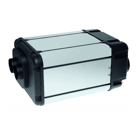
Parking heater for mercedes benz c-class s204, w204 / mercedes benz c-class c204 / glk-class x204 (38 pages)
Summary of Contents for Webasto Dual Top Evo 6
Page 1
Air heaters 03/2003 Integrated Heater Workshop Manual Dual Top Evo 6 / 7 / 8...
Page 2
Only genuine Webasto parts may be used. See also Webasto air and water heaters accessories catalogue. NEVER try to install or repair Webasto heating or cooling systems if you have not completed a Webasto training course, you do not have the necessary technical skills and you do not have the technical documentation, tools and equipment available to ensure that you can complete the installation and repair work properly.
Dual Top Evo 6 / 7 / 8 Table of Contents Table of Contents Introduction ....................... 101 Contents and purpose ..........................101 1.1.1 Use of the integrated heaters ......................101 Meaning of signal words ..........................101 Additional documentation to be used ......................101 Statutory regulations and safety instructions ....................101 1.4.1 Statutory regulations governing installation ..................101...
Page 4
8.3.7 Removing housing and insulating elements ..................815 8.3.8 Installing heating air blower assembly ....................815 8.3.9 Installing housing cover ........................816 Replacement of older Dual Top RHA 100/ Dual Top Evo 6 version with newer one ........818 Packaging, storage and shipping ................901 General ..............................901...
1.1.1 Use of the integrated heaters The Webasto Dual Top integrated air / water heaters are 1.4.1 Statutory regulations governing designed to heat and to provide hot water in motor homes installation and similar vehicles.
1 Introduction Dual Top Evo 6 / 7 / 8 1.4.2 General safety information Wherever inflammable vapours or dust may form (for example in the vicinity of fuel, carbon, wood dust or cereal Follow all the safety informations described in the additional stores or the like), the heater must be switched off as a result documentation thoroughly.
Page 7
Dual Top Evo 6 / 7 / 8 1 Introduction Air lines must be firmly secured on the heater and at all other connection points (e.g. air outlets) (e.g. with pipe clamps). IMPORTANT: The faults described in the following must always be avoided: •...
2 General description Dual Top Evo 6 / 7 / 8 General description The integrated Dual Top Evo 6, 7 and 8 heaters designed according to the evaporator principle mainly consists of: – the heating air blower assembly (PWM module and motor with heating air blower) –...
Page 9
Dual Top Evo 6 / 7 / 8 2 General description Fig. 201 Dual Top Evo Heater Housing cover with inlet interfaces Housing cover with hot air outlet Solenoid valve Air temperature sensor Ventilation/overpressure valve Air temperature switch Combustion air blower...
3 Technical data Dual Top Evo 6 / 7 / 8 Technical data Fuel for Dual Top The diesel fuel DIN EN 590 specified by the manufacturer must be used. Class EL heating oil, L heating oil or PME (bio- Except where limit values are specified, the technical data diesel) must not be used.
Page 11
Dual Top Evo 6 / 7 / 8 3 Technical data Table 302 Technical Data - Dual Top Evo 7/8 Heater Operation Dual Top Evo 7 Dual Top Evo 8 Type approval heater: e1 00 0195 EMC: e1 03 5000...
4 Troubleshooting Dual Top Evo 6 / 7 / 8 Troubleshooting General information If individual components are checked, then the electrical connections on the control unit must be disconnected. Many faults are caused by improper installation. Installation Carry out a functional check in the vehicle each time a fault errors should always be corrected or a fault of the system is eliminated.
Manual control panel – Switch on heater on control panel – Heater does not react, F10 is indicated (10 red flashing The manual control panel is used for Dual Top Evo 6 heaters pulses) only. – Remove 5 A fuse (control panel) –...
Page 14
4 Troubleshooting Dual Top Evo 6 / 7 / 8 Table 402 Fault messages manual control panel No communication between control 1 Check battery charge. panel and heater, or a control panel 2 Check control panel connections. error 3 Check 15 A fuse (red wire, thermo unit).
Page 15
Dual Top Evo 6 / 7 / 8 4 Troubleshooting Table 402 Fault messages manual control panel Overheating of air temperature sensor 1 Ensure that cold and hot air can flow freely, air intake and in heater outlets are not blocked.
– Install 15 A fuse (red/black wire, PWM module) – Install 5 A fuse (control panel) – Switch on heater on control panel Now the heater is reset. Deleting failures can also be done with the Webasto Thermo Test PC-Diagnosis.
Page 17
Dual Top Evo 6 / 7 / 8 4 Troubleshooting Table 403 Fault messages programmable control panel Message 01 No communication between con- 1 Check battery charge. No data connec- trol panel and heater, or faulty con- 2 Check control panel connections.
Page 18
4 Troubleshooting Dual Top Evo 6 / 7 / 8 Table 403 Fault messages programmable control panel Message 08 Fault in motor of heating air blow- 1 Check power supply: Fuse correct (fuse not dam- Failure hot air er: Disconnection / short circuit /...
Page 19
Dual Top Evo 6 / 7 / 8 4 Troubleshooting Table 403 Fault messages programmable control panel Message 14 Overheating of heater control unit Ensure that cooling air can flow freely, Failure cooling air reset heater (by pressing OK or switching off for at least ventilation 5 sec.)
Page 20
4 Troubleshooting Dual Top Evo 6 / 7 / 8 Table 403 Fault messages programmable control panel Message 27 Short circuit of 230 V indication sig- 1 Check wiring harness relay box to heater. Failure relay box nal from relay box to heater 2 Check relay box and connections relay box.
Dual Top Evo 6 / 7 / 8 5 Function tests Function tests General 5.2.1.3 Air temperature sensor resistance test If you conduct this test with a digital multimeter, the air This section describes the tests conducted on the heater temperature sensor (see Fig.
5 Function tests Dual Top Evo 6 / 7 / 8 5.2.1.9 Resistance measurement for external room Table 501 Technical data water temperature sensor temperature sensor Temperature Resistance Resistance Resistance [°C] nominal min. max. Table 502 Technical data of external room...
Page 23
Dual Top Evo 6 / 7 / 8 5 Function tests Fig. 503 Sensor positions 1 = Water temperature sensor Is only monitored by the control unit when hot water is provided and for frost protection 2 = Water temperature switch...
6 Circuit diagrams Dual Top Evo 6 / 7 / 8 Circuit diagrams General Fig. 601 shows the heater control unit. Circuit diagrams: Fig. 606 for wiring harness of RHA 100 (wiring harness How the electrical connections are to be made: connector inside, older version), Fig.
Page 25
9 External room temperature sensor 5 Fuse 5 A 10 Cable for external room temperature sensor Fig. 602 Schematic diagram of electrical connections for Dual Top Evo 6 1 Heater Dual Top 7 Fuse 15 A 11 Receiver Telestart / Thermo Call...
Page 26
X0 (2-pin) of room temperature sensor to control panel X2 is for: – Webasto Thermo Test PC-diagnosis and – Webasto Telestart / Thermo Call (for optional programmable control panel). X4 (4-pin) of wiring harness to control panel Fig. 604 Electrical connections Manual control panel...
Page 27
Dual Top Evo 6 / 7 / 8 6 Circuit diagrams Fig. 606 Wiring harness for Dual Top RHA 100 (older version, heater Ident. No. 9015314A and 9015314B)
Page 28
6 Circuit diagrams Dual Top Evo 6 / 7 / 8 Fig. 607 Wiring diagram for Dual Top RHA 100 (newer version, heater Ident. No. 9015314C) and Dual Top Evo 6...
Page 29
Dual Top Evo 6 / 7 / 8 6 Circuit diagrams Fig. 608 Wiring diagram for Dual Top Evo 7/8...
Page 30
Plug connector, 2-pin To control panel (external room temperature sensor) Plug connector, 2-pin 2 pcs, to electric heater inside Dual Top (not for Dual Top Evo 6) Plug connector, 4-pin To PC-diagnosis / Telestart / Thermo Call Plug connector, 2-pin...
Page 31
Dual Top Evo 6 / 7 / 8 6 Circuit diagrams Table 602 Cable colours Abbreviation Colour blue brown yellow green grey orange black violet white...
7 Servicing work Dual Top Evo 6 / 7 / 8 Servicing work General The CO setting is carried out with Webasto Thermo Test PC Diagnostics. This section describes the servicing work that can be carried The heater is optimally set to a CO value at the factory for out on the heater when it is installed.
Dual Top Evo 6 / 7 / 8 7 Servicing work Service work To ensure functional reliability of the heater the following servicing must be performed in regular intervals: • the heater must be switched "OFF" before cleaning. • clean heater exterior (do not use high-pressure water or air hoses, prevent the ingress of water).
See Installation Instructions. 7.8.2.3 Installation See Installation Instructions. 7.8.2 Control panel, removal and installation 7.8.2.1 Manual control panel (for Dual Top Evo 6) Start-up 1. Disconnect the battery. After each heater disassembly, follow the procedure "Start- 2. Remove control panel as shown (see Fig. 701).
Dual Top Evo 6 / 7 / 8 8 Repair Repair General Dismantling heater This section describes the repair work that may be carried out So that you can check or replace a component of the on the Dual Top heater after it has been removed from the Dual Top heater, you should dismantle the heater until you vehicle.
Page 36
8 Repair Dual Top Evo 6 / 7 / 8 Loosen 8 screws T25, then remove housing cover with inlet Loosen 8 screws T25, then remove housing cover with hot air interfaces. outlet incl. boiler gasket. Only Dual Top Evo immersion pump version:...
Dual Top Evo 6 / 7 / 8 8 Repair 8.2.2 Removing heating air blower assembly 8.2.3 Removing housing and insulating elements Loosen 2 screws T30 of heating air blower assembly with Loosen 4 T30 screws on bottom of Dual Top.
8 Repair Dual Top Evo 6 / 7 / 8 Pull 2 1-pin plugs out of solenoid valve. Use flat (-) screwdriver to push down ring of connector hot and cold water pipes and pull pipes up to remove them from boiler.
Dual Top Evo 6 / 7 / 8 8 Repair Backside boiler: Loosen 7 mm hex nut that attaches water Loosen 2 T10 screws that hold overheat switch to backside temperature switch and water temperature sensor of sensor heat exchanger.
8 Repair Dual Top Evo 6 / 7 / 8 8.2.7 Removing control unit and internal wiring Disconnect 5 plugs of internal wiring harness from control unit. harness Loosen screw T20 that attaches brown wire to control unit. Remove exhaust gasket from exhaust and cooling air outlet.
Dual Top Evo 6 / 7 / 8 8 Repair Assembling Guide glow plug into evaporator housing assembly and fasten with retaining spring. 8.3.1 Installing evaporator housing assembly, glow plug and combustion pipe assembly Guide fuel line from inside to outside through large hole in bottom of heat exchanger.
8 Repair Dual Top Evo 6 / 7 / 8 8.3.2 Installing drive Attach flat gasket heat exchanger and drive assembly to heat exchanger and fix with 8 screws T20. Fix combustion air intake incl. connection gasket to drive assembly with 3 screws T20.
Dual Top Evo 6 / 7 / 8 8 Repair 8.3.3 Installing control unit and internal wiring Put gasket exhaust on exhaust and cooling air outlet. harness Connect 2 plugs from thermo unit (Y1 and Y2, see Fig. 601) and 5 plugs of internal wiring harness (Y3, Y4, Y5, Y6 and Y7, see Fig.
8 Repair Dual Top Evo 6 / 7 / 8 8.3.4 Installing electrical heating elements 8.3.5 Installing thermo unit, sensors and sensor wiring harness Only for Dual Top Evo 7/8: Slide electrical heating element from backside into the heat Fix overheating protector to backside heat exchanger with 2 exchanger.
Dual Top Evo 6 / 7 / 8 8 Repair Connect plug 8 poles of sensor wiring harness to internal 8.3.6 Installing ventilation/overpressure valve wiring harness. and solenoid valve Put pink coloured silicon pad on 2 threaded studs M4 at...
Page 48
8 Repair Dual Top Evo 6 / 7 / 8 Attach self-adhesive insulation ventilation/overpressure valve Dual Top Evo standard version: (top) and solenoid valve (bottom). Connect drain hose to 2 openings on ventilation/ overpressure valve (A, D) and to 1 opening on solenoid valve (B).
Dual Top Evo 6 / 7 / 8 8 Repair 8.3.7 Removing housing and insulating elements 8.3.8 Installing heating air blower assembly Fit 2 insulation elements on top and bottom of unit (parts are Connect 4-pin plug of internal wiring harness to PWM identical).
8 Repair Dual Top Evo 6 / 7 / 8 8.3.9 Installing housing cover Install air intake grill and cooling shell foam gasket. Fix hold metal plate (with air temperature sensor and air temperature switch) of sensor wiring harness to housing cover with hot air outlet with 2 T20 screws.
Page 51
Dual Top Evo 6 / 7 / 8 8 Repair Fasten housing cover with inlet interfaces on Dual Top with 8 T25 screws. Tightening torque: 6 Nm. NOTE: Housing cover with inlet interfaces must fit into respective groove of grommets for wiring harnesses (1 pc.
Page 52
8 Repair Dual Top Evo 6 / 7 / 8 Replacement of older Dual Top RHA 4 Secure lines for fuel pump of old wiring harness (orange and green/white cables). 100/ Dual Top Evo 6 version with 5 Strip 6 wires of old wiring harness (vehicle side) approx.
Dual Top Evo 6 / 7 / 8 9 Packaging, storage and shipping Packaging, storage and shipping General The heater or its components which are sent to Webasto for testing must be cleaned and packaged so that they are protected against damage when handled, transported and stored.
Page 54
9 Packaging, storage and shipping Dual Top Evo 6 / 7 / 8...
Page 55
The telephone number of each country can be found in the Webasto service center leaflet or the website of the respective Webasto representative of your country. Webasto Thermo & Comfort SE Postfach 1410 82199 Gilching Germany Visiting address: Friedrichshafener Str. 9...
Need help?
Do you have a question about the Dual Top Evo 6 and is the answer not in the manual?
Questions and answers