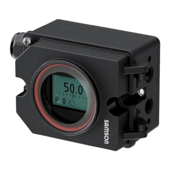
Samson 3725 Series Mounting And Operating Instructions
Electropneumatic positioner
Hide thumbs
Also See for 3725 Series:
- Mounting and operating instructions (80 pages) ,
- Datasheet (4 pages) ,
- Mounting and operating instructions (56 pages)

Related Manuals for Samson 3725 Series


Summary of Contents for Samson 3725 Series
- Page 1 EB 8394 EN Translation of original instructions Hardware version 01.xx.xx Hardware version GI:00 Series 3725 Type 3725 Electropneumatic Positioner Firmware version 1.12 Edition November 2024...
- Page 2 Note on these mounting and operating instructions These mounting and operating instructions assist you in mounting and operating the device safely. The instructions are binding for handling SAMSON devices. The images shown in these instructions are for illustration purposes only. The actual product may vary.
-
Page 3: Table Of Contents
Contents Safety instructions and measures ..............6 Notes on possible severe personal injury ............9 Notes on possible personal injury ..............10 Notes on possible property damage ..............10 Markings on the device ................12 Nameplate ....................12 Article code ....................13 Design and principle of operation ..............16 Types of attachment ..................16 Accessories and mounting parts ..............18 Travel tables ....................22... - Page 4 Contents Operation ....................52 Operating controls ..................52 6.1.1 Capacitive keys ....................52 6.1.2 Volume restriction Q ..................52 6.1.3 Display .......................53 Operating the positioner ................54 Adapting the display ..................55 7.2 Enabling configuration to change parameters..........55 7.3 Adjusting the volume restriction Q ..............56 Entering the direction of action ..............57 Entering the direction of action ..............57 Limiting the signal pressure ................58 Setting other parameters ................59 Initialization ....................59...
- Page 5 Contents Firmware revisions 1.02 (old) 1.03 (new) Internal revisions 1.03 (old) 1.10 (new) Setting of the travel in steps of 0.5 mm (P4 parameter code) Monitoring of the end stops only during initialization and in manual mode To suppress common-mode interference on the signal lines, the D component of the positioner is switched off when the actuator is at a standstill. 1.10 (old) 1.11 (new) Internal revisions...
-
Page 6: Safety Instructions And Measures
In case operators intend to use the positioner in applications or conditions other than those specified, contact SAMSON. SAMSON does not assume any liability for damage resulting from the failure to use the de- vice for its intended purpose or for damage caused by external forces or any other external factors. - Page 7 Î Check with the plant operator for details on further protective equipment. Revisions and other modifications Revisions, conversions or other modifications of the product are not authorized by SAMSON. They are performed at the user's own risk and may lead to safety hazards, for example. Furthermore, the product may no longer meet the requirements for its intended use.
- Page 8 Safety instructions and measures Servicing explosion-protected devices If a part of the device on which the explosion protection is based needs to be serviced, the device must not be put back into operation until a qualified inspector has assessed it accord- ing to explosion protection requirements, has issued an inspection certificate, or given the device a mark of conformity. Inspection by a qualified inspector is not required if the manu- facturer performs a routine test on the device before putting it back into operation and the passing of the routine test is documented by attaching a mark of conformity to the device.
-
Page 9: Notes On Possible Severe Personal Injury
Safety instructions and measures 1.1 Notes on possible severe personal injury DANGER Risk of fatal injury due to the ignition of an explosive atmosphere. Incorrect installation, operation or maintenance of the positioner in potentially explosive atmospheres may lead to ignition of the atmosphere and ultimately to death. Î... -
Page 10: Notes On Possible Personal Injury
Safety instructions and measures 1.2 Notes on possible personal injury WARNING Risk of personal injury due to moving parts on the valve. During initialization of the positioner and during operation, the valve moves through its entire travel range. Injury to hands or fingers is possible if they are inserted into the valve. Î During initialization, do not insert hands or fingers into the valve yoke and do not touch any moving valve parts. 1.3 Notes on possible property damage NOTICE Risk of damage to the positioner due to incorrect mounting position. - Page 11 Safety instructions and measures Malfunction due to initialization not yet completed. The initialization causes the positioner to be calibrated to adapt it to the mounting situa- tion. After initialization is completed, the positioner is ready for use. Î Initialize the positioner on first start-up. Î Re-initialize positioner after changing the mounting position. Risk of positioner damage due to incorrect grounding of the electric welding equip- ment.
-
Page 12: Markings On The Device
Input Input See technical data for ambient temperature Date Date Mat. Mat. Model 3725- SAMSON AG D-60314 Frankfurt Made in Germany Model 3725- SAMSON AG Weismuellerstrasse 3 Made in D-60314 Frankfurt Germany Supply pressure Serial number Input signal Model number... -
Page 13: Article Code
Markings on the device 2.2 Article code Positioner Type 3725- x x x 0 0 0 0 x 0 0 x x x x With LCD and autotune, 4 to 20 mA reference variable Explosion protection Without 0 0 0 ATEX 1 1 0 II 2 G Ex ia IIC T4 Gb CCC Ex 1 1 2 Ex ia II T4 Gb... - Page 14 Markings on the device Table 1: Summary of explosion protection certificates Type Certification Type of protection Number PTB 11 ATEX 2020 X ATEX 3725-1000 II 2 G Ex ia IIC T4 Gb Date 2019-02-25 Number 2021322307003871 CCC Ex 3725-112 Date 2023-04-29 Ex ia II T4 Gb Valid until 2026-04-04 Number...
- Page 15 EB 8394 EN...
-
Page 16: Design And Principle Of Operation
The Type 3725 Positioner is suitable for the The pick-up lever is connected to a magnet following types of attachment: inside the device. The motion of the pick-up − Direct attachment to SAMSON lever causes the direction of the magnetic Type 3277 and Type 2780-2 Actuators field to change. This change is sensed by the sensor (2). The electronics unit determines −... - Page 17 Design and principle of operation Valve Air booster Sensor Pressure regulator A/D converter Fixed restriction Microcontroller Volume restriction D/A converter Display i/p converter Fig. 1: Circuit diagram EB 8394 EN...
-
Page 18: Accessories And Mounting Parts
Design and principle of operation 3.2 Accessories and mounting parts Table 3: Direct attachment to Type 3277-5 and Type 2780-2 Actuators (see Order no. Chapter 5.2) Mounting parts For actuators up to 120 cm² 1402-0239 Accessories for actuator Switchover plate for Type 3277-5xxxxxx.01 Actuator 1400-6822 Connecting plate for additional attachment of, e.g. a solenoid valve: G 1400-6823 Accessories for positioner G ¼... - Page 19 Design and principle of operation Table 5: Pipe connections for Type 3277 (direct attachment) Pipe connection Actuator size Material Connection Order no. G ¼ / G 1402-0930 Steel ¼ NPT/ NPT 1402-0958 175 cm² G ¼ / G 1402-0950 Stainless steel ¼ NPT/ NPT 1402-0964 G ¼ / G 1402-0927 Steel ¼ NPT/ NPT 1402-0959...
- Page 20 Stainless steel/stainless steel 1402-1638 Order no. Table 7: Attachment to rotary actuators (Chapter 5.5) Light version 1402-0243 VDI/VDE 3845 (September 2010), fixing level 1 , AA1 size VDI/VDE 3845 (September 2010), fixing level 1 , AA2 size 1402-0244 VETEC Type S160 Actuator or SAMSON Type 3278 Rotary Actuator (160 cm²) 1402-0294 VETEC Type S320 1402-0295 Heavy-duty version VDI/VDE 3845 (September 2010), fixing level 1 , AA1 to AA4 size 1402-1097 VDI/VDE 3845 (September 2010), fixing level 2 1402-1099 VETEC Type S160/R...
- Page 21 Design and principle of operation Order no. Table 8: General accessories and spare parts M20x1.5 cable gland Black plastic 8808-1011 Blue plastic 8808-1012 Nickel-plated brass 1890-4875 Stainless steel 1.4305 8808-0160 M20x1.5 to ½ NPT adapter Powder-coated aluminum 0310-2149 Stainless steel 1400-7114 Brief instructions inside cover GI:00 0190-6173...
-
Page 22: Travel Tables
Rated travel lever pin position [cm²] [mm] Min. Travel Max. 6/12 5.0 mm 16.0 mm 7.0 mm 22.0 mm Attachment according to IEC 60534-6 (NAMUR) SAMSON Required Assigned Type 3271 Actuator Travel of other valves Rated travel lever pin position Size [cm²] [mm] Min. Max. 5.0 mm 16.0/25.0 ... -
Page 23: Technical Data
Design and principle of operation 3.4 Technical data Type 3725 Positioner Travel (adjustable) Direct attachment to Type 3277: 5 to 30 mm Direct attachment to Type 2780-2: 6/12/15 mm Attachment to Type 3372 Actuator: 15/30 mm Attachment according to IEC 60534-6 (NAMUR): 5 to 50 mm Attachment to rotary actuators: 24 to 100°... - Page 24 Design and principle of operation Safety Influences Temperature: ≤0.15 %/10 K Effect of vibration: ≤0.25 % up to 2000 Hz and 4 g according to IEC 770 Supply air: None Electromagnetic Complying with EN 61000-6-2, EN 61000-6-3 and NAMUR Recommendation NE 21 compatibility Explosion protection See Table 1 on page 14 for details on explosion protection certificates. Degree of protection IP 66 Conformity Materials Housing Polyphthalamide (PPA) Cover GI:00 Cover with integrated square window: polycarbonate (PC) HV 01.00.00 Cover made of polyphthalamide (PPA) with round window made of polycarbonate (PC)
-
Page 25: Dimensions In Mm
Design and principle of operation 3.5 Dimensions in mm M20x1.5 M20x1.5 62,50 Fig. 2: Dimensional drawings for Type 3725 Positioner (hardware version GI:00) EB 8394 EN 62.50... - Page 26 Design and principle of operation M20x1.5 62,50 Fig. 3: Dimensional drawings for Type 3725 Positioner (hardware version HV 01.00.00) EB 8394 EN...
- Page 27 Design and principle of operation Fixing levels according to VDI/VDE 3845 (September 2010) Fixing level 2 (bracket surface) Fixing level 1 (actuator surface) Actuator Dimensions in mm Size Ød ØD 5.5 for M5 5.5 for M5 5.5 for M5 ØD 5.5 for M5 5.5 for M5 6.5 for M6 Flange type F05 acc. to DIN EN ISO 5211...
- Page 28 EB 8394 EN...
-
Page 29: Measures For Preparation
Risk of positioner damage due to improper age. storage. Î Observe the storage instructions. 4.1 Unpacking Î Avoid longer storage periods. Î Contact SAMSON in case of different storage conditions or longer storage NOTICE times. Risk of positioner damage due to foreign particles entering it. -
Page 30: Mounting And Start-Up
Mounting and start-up 5 Mounting and start-up 5.1 Lever and pin position The positioner is adapted to the actuator and NOTICE to the rated travel by the lever on the back of Risk of malfunction due to incorrect se- the positioner and the pin inserted into the quence of mounting, installation and lever. - Page 31 Mounting and start-up Fig. 4: M lever with pin position 35 Top stop Vent opening Bottom stop Fig. 5: Mechanical stops and vent opening EB 8394 EN...
-
Page 32: Direct Attachment
Mounting and start-up 5.2 Direct attachment 4. 15 mm travel: Keep the follower pin (2) on the M lever (1) on the back of the po- 5.2.1 Type 3277-5 and sitioner in the pin position 35 (delivered state). 7.5 mm travel: Remove the fol- Type 2780-2 Actuators lower pin (2) from the pin position 35, Î... - Page 33 Mounting and start-up Lever 1.1 Nut Symbols Switchover plate (9) 1.2 Disk spring Follower pin Actuator stem Follower clamp extends Screw plug Stopper Left attachment Right attachment Connecting plate 6.1 Seals Pressure gauge Actuator stem bracket retracts Pressure gauge Signal pressure mounting kit input for left Switchover plate...
- Page 34 Mounting and start-up Additional solenoid valve If a solenoid valve is additionally mounted onto the actuator, the signal pressure port at the back of the positioner must be sealed (see Fig. 9). To do this, unscrew the screw plug located in the middle hole (screw plug in park position) and screw it into the signal pressure port to seal it.
- Page 35 Mounting and start-up Screw plug (4) (signal pressure port) Park position Fastening screw Fig. 9: Signal pressure port and park position for screw plug EB 8394 EN...
-
Page 36: Type 3277 Actuator
Mounting and start-up 5.2.2 Type 3277 Actuator The lever (1) must rest on the follower clamp with spring force. Î Required mounting parts and accesso- Fasten the positioner on the actuator us- ries: Table 4 on page 18. ing the two fixing screws. Î Observe travel tables on page 22. 5. Make sure that the tip of the gasket (16) projecting from the side of the connec- Actuators with 175 to 750 cm²... - Page 37 Mounting and start-up Type 3277 Actuator with Type 3725 10 15 1 2 3 Positioner (direct attachment) (image shows device cover of hardware version GI:00) Ansicht A SUPPLY 12.1 12.2 M lever Disk spring Follower pin Follower clamp Cover Connection block Ansicht A 12.1 Screw 12.2 Stopper or connection for external piping...
-
Page 38: Attachment According To Iec 60534-6
Mounting and start-up 5.3 Attachment according to the slot of the follower plate (3). Adjust the lever (1) correspondingly. IEC 60534-6 Fasten the positioner to the NAMUR The positioner is attached to the control valve bracket using its two mounting screws. using a NAMUR bracket (10). Î Required mounting parts and accesso- ries: Table 6 on page 20. Î... - Page 39 Mounting and start-up Attachment to rod-type yoke 20 to 35 mm rod diameter Lever 14.1 Disk spring Follower pin Follower plate Connecting plate Seals Pressure gauge bracket Pressure gauge Stem connector Bracket NAMUR bracket Screw Bolt 14.1 Screws Travel indicator scale U-bolt Fig. 11: Attachment according to IEC 60534-6 EB 8394 EN...
-
Page 40: Attachment To Type 3372 Actuator (V2001)
Mounting and start-up 5.4 Attachment to Type 3372 Actuator (V2001) The Type 3725 Positioner is already included in the scope of delivery for Series V2001 Valves (Fig. 12). The attachment is briefly described below to allow conversion work to be performed. Actuator with 120/350 cm², stem extends The signal pressure is routed through the cor- responding port in the support element to the actuator diaphragm. - Page 41 Mounting and start-up Type 3372 Actuator, version with 120 cm² Type 3372 Actuator, version with 350 cm² Fig. 12: Attachment to Type 3372 Actuator (image shows device cover of hardware version GI:00) EB 8394 EN...
-
Page 42: Attachment To Rotary Actuators
Table 7 on page 20. side of the positioner when the actuator Î Before attaching the positioner onto the is at half its angle of rotation. SAMSON Type 3278 Rotary Actuator 8. Stick the scale plate on the coupling (160 cm²) or VETEC Type S160 Actuator, wheel (4) so that the arrow tip indicates... - Page 43 Seals Disk spring Pressure gauge bracket Follower pin Pressure gauge mounting Follower clamp Coupling wheel Mounting bracket Screw 10.1 Screws Disk spring Adapter Actuator shaft 10.1 10.1 10.1 Attachment to SAMSON Type 3278 Attachment according to VDI/VDE 3845, level 1 Rotary Actuator (160 cm²) or VETEC Type S160 Actuator Fig. 14: Attachment to rotary actuators EB 8394 EN...
-
Page 44: Heavy-Duty Version
1400-6964) into the signal pres- sary. sure output of the positioner (or the out- put of the pressure gauge bracket or con- 2. For SAMSON Type 3278 and VETEC necting plate). S160 Rotary Actuators, fasten the adapter (5) onto the free end of the shaft 8. - Page 45 Disk spring Spacer Adhesive label Adapter plate Actuator shaft or adapter 10.1 10.1 SAMSON Type 3278 Attachment according to VDI/VDE 3845 VETEC S160, VETEC R (Sept. 2010) Fixing level 1, AA1 to AA4 size, see page 27 Fig. 16: Attachment to rotary actuators (heavy-duty version)
-
Page 46: Mounting The Type 3710 Reversing Amplifier
Mounting and start-up 5.5.2 Mounting the Type 3710 Reversing Amplifier When a Type 3710 Reversing Amplifier is used, a connecting plate is placed between the positioner and reversing amplifier. The reversing amplifier is fastened together with the connecting plate to the positioner using screws (Fig. 17). Note The screws supplied with the connecting plate have a TORX PLUS profile (size 25 IP) ®... -
Page 47: Pneumatic Connections
Mounting and start-up 5.6 Pneumatic connections NOTICE Risk of malfunction due to failure to comply WARNING with air quality requirements. Risk of injury by possible movement of the Î Only use supply air that is dry and free actuator stem after connecting the signal of oil and dust. -
Page 48: Supply Pressure
= Seat diameter [cm] Differential pressure across the ∆p = valve [bar] To monitor the supply air and signal pres- sure, SAMSON recommends mounting pres- = Actuator area [cm²] sure gauges (see Table 7 in Chapter 3.2). = Upper bench range value [bar] If there are no specifications, calculate as Mounting the pressure gauges: follows: Î... -
Page 49: Electrical Connections
Mounting and start-up 5.8 Electrical connections DANGER Risk of fatal injury due to the formation of an explosive atmosphere. For installation in hazardous areas, observe the relevant standards that apply in the country of use. Standard applicable in Germany: EN 60079-14 (VDE 0165, Part 1) Explosive Atmo- spheres –... -
Page 50: Electric Power Supply
Mounting and start-up 5.8.2 Cable entry Equipment for use in zone 2/zone 22 In equipment operated according to type of The M20x1.5 cable gland is designed for a protection Ex nA II (non-sparking equipment) clamping range of 6 to 12 mm. according to EN 60079-15: 2003: The cage clamp terminals hold wire Î Circuits may be connected, interrupted cross-sections of 0.2 to 1.5 mm². - Page 51 Mounting and start-up Plastic part Terminal assignment for mA control signal: Fig. 18: Electrical connections EB 8394 EN...
-
Page 52: Operation
Operation 6 Operation 6.1 Operating controls The positioner is operated using three capacitive keys. These capacitive keys allow the user to navigate within the menu on the display (Fig. 19). The volume restriction Q serves to adapt the air output capacity to the size of the actuator: 6.1.1 Capacitive keys : Up : Confirm... -
Page 53: Display
Operation 6.1.3 Display Icons which are assigned to certain codes and functions are indicated on the display (Fig. 19). The bar elements indicate the system deviation that depends on the sign (+/–) and the value. One bar element appears per 1 % system deviation. If the positioner has not yet been initialized, the lever position in degrees in relation to the mid-axis is indicated. -
Page 54: Operating The Positioner
Operating the positioner 7 Operating the positioner Before start-up, mount the positioner following the sequence described in Chapter 5. Apply the electric reference variable to start up the positioner (see Chapter 5.8.3). Note − LOW on the display indicates that the reference variable is lower than 3.8 mA. − The positioner is ready for operation with its default settings for most applications. − After connecting the electrical signal (power supply), the positioner performs a calibration of the capacitive keys which takes approx. -
Page 55: Adapting The Display
Operating the positioner 7.1 Adapting the display The display reading direction can be rotated by 180°. If the displayed data appear upside down, proceed as follows: 6. Touch until Code P1 appears. 7. Press to confirm the selected code. P1 blinks. 8. Touch until the display is set in the desired direction. 9. -
Page 56: Adjusting The Volume Restriction Q
Operating the positioner 7.3 Adjusting the volume restriction Q The volume restriction Q (see Fig. 20) serves to adapt the air output capacity to the size of the actuator: Actuators with a transit time < 1 s, e.g. linear actuators with an effective area smaller than 240 cm², require a restricted air flow rate. -
Page 57: Entering The Direction Of Action
Operating the positioner 7.4 Entering the direction of action − ATO (air to open) applies to a valve opening as the signal pressure increases. − ATC (air to close) applies to a valve closing as the signal pressure increases. The signal pressure is the pneumatic pressure at the output of the positioner applied to the actuator. -
Page 58: Limiting The Signal Pressure
Operating the positioner The following correlation applies: Valve CLOSED OPEN Display 100 % Direction of action increasing/increasing (>>) 4 mA 20 mA Direction of action increasing/decreasing (<>) 20 mA 4 mA 7.6 Limiting the signal pressure If the maximum actuator force is too high for the valve used, the signal pressure limit can be activated in Code P9. The pressure is then limited to approx. 2.3 bar. -
Page 59: Setting Other Parameters
Operating the positioner 7.7 Setting other parameters The following table lists all the parameter codes and their default settings. Proceed as de- scribed previously to change parameters. More details concerning the parameter codes can be found in Chapter 11.2. Parameter codes [default settings] Set point cutoff decrease (end position w <) Status reading [ON] Set point cutoff increase (end position w >) Reading direction... -
Page 60: Canceling Initialization
Operating the positioner The type and extent of self-adaptation depends on the preset parameters. MAX applies as the default setting for the nominal range (Code P4). During the initialization process, the po- sitioner determines the total travel range or rotational range of the valve (from the CLOSED position to the opposite end position). -
Page 61: Zero Calibration
Operating the positioner Initial state 1: The positioner is not initialized. The positioner goes to the fail-safe position after the initialization process has been canceled. Initial state 2: The positioner is initialized. On canceling a new initialization process, the positioner returns to closed-loop operation. The settings of the previous initialization are used. -
Page 62: Manual Mode
Operating the positioner Note This code must be confirmed by pressing . Otherwise, the code remains active. The positioner changes to closed-loop operation without performing a zero calibration. A new zero calibration can be started directly afterwards. 7.10 Manual mode The valve position can be moved as follows using the Manual mode function: Enable configuration as described in Chapter 7.2. -
Page 63: Reset
Operating the positioner Note The Manual mode function can only be exited as described or by interrupting the electrical supply (cold start). The positioner does not automatically exit this function and return to the display showing the status indication. 7.11 Reset A reset causes an initialization to be undone and all parameters settings are reset to the de- fault settings (see code list in Chapter 11.2). -
Page 64: Servicing
− The product warranty becomes void if service or repair work not described in these instruc- tions is performed without prior agreement by SAMSON's After-sales Service. − Only use original spare parts by SAMSON, which comply with the original specifications. The Type 3725 Positioner requires no maintenance. There are filters with a 100 µm mesh size in the pneumatic connections for supply and output which can be removed and cleaned, if required. -
Page 65: Malfunctions
Malfunctions 9 Malfunctions In case of a fault, the fault indication icon is displayed. Switch past Code P0 or P20 to dis- play the respective error code E0 to E15 together with ERR appear on the display. Refer to the error code list in Chapter 9.2 for the cause of the errors and the recommended action. Example: If, for instance, a travel has been entered in Code P4 (nominal range) which is larger than the maximum valve travel possible, the initialization process would be interrupted (E2 error... -
Page 66: Clearing Error Codes
Malfunctions 9.1 Clearing error codes The E0 and E8 error codes can be cleared as follows: 4. Touch to select the error code. 5. Touch to confirm the error code. ESC is displayed and the er- ror code blinks. 6. Touch until RST appears. 7. Press to clear the error. -
Page 67: Error Codes
The errors listed in the following table are assigned to error classes: Error class 1: No operation possible Error class 2: Manual operation only possible Error class 3: Manual operation and closed-loop control possible Contact SAMSON's After-sales Service for malfunctions not listed in the table in Chap- ter 11.1. Code Description... -
Page 68: Emergency Action
Recommended action Clear error code (see Chapter 9.1). Check positioner mounting and re-initialize the positioner. Device error (internal) Return device to SAMSON for repair. 9.3 Emergency action Upon failure of the air supply and/or electrical signal, the positioner vents the actuator, caus- ing the valve to move to the fail-safe position determined by the actuator. -
Page 69: Decommissioning And Removal
10.1 Decommissioning Note To decommission the positioner before re- SAMSON can provide you with a recy- moving it, proceed as follows: cling passport according to PAS 1049 1. Disconnect and lock the air supply and on request. Simply e-mail us at signal pressure. -
Page 70: Appendix
E-mail address You can reach our after-sales service at aftersalesservice@samsongroup.com. Addresses of SAMSON AG and its subsid- iaries The addresses of SAMSON AG, its subsid- iaries, representatives and service facilities worldwide can be found on our website (www.samsongroup.com) or in all SAMSON product catalogs. Required specifications Please submit the following details: −... -
Page 71: Code List
Appendix 11.2 Code list 11.2.1 Parameter codes Code Display, values Description [default setting] Note: Codes marked by an asterisk (*) indicate that the positioner needs to be re-initialized afterwards Status reading with The reading indicates the valve position or angle of rotation in % basic information when the positioner is initialized. On touching when the positioner is not initialized, the position of the lever in relation to the mid-axis is displayed. - Page 72 Appendix Characteristic Select characteristic: 0 to 8 0, 1, 2 for globe valves, 0 to 8 with rotary actuators (P3 = 90°) Linear Equal percentage Reverse equal percentage SAMSON butterfly valve, linear SAMSON butterfly valve, equal percentage VETEC rotary plug valve, linear VETEC rotary plug valve, equal percentage Segmented ball valve, linear Segmented ball valve, equal percentage Reference variable For split-range operation: [4 to 20 mA] SRLO: low range 4 to 11.9 mA SRLO/SRHI SRHI: high range 12.1 to 20 mA Direction of action of the reference variable w to the travel/ [>>]/<>...
- Page 73 Appendix Press button to cancel the initialization process. As a result, the Start initialization valve moves to the fail-safe position. After a power supply failure during initialization, the positioner starts with the values of the last initialization (if available). The zero calibration process can be interrupted by touching Start zero calibration The control valve returns to closed-loop operation.
- Page 74 EMC 2014/30/EU +A1:2011, EN 61326-1:2013 RoHS 2011/65/EU EN 50581:2012 Hersteller / Manufacturer / Fabricant: SAMSON AKTIENGESELLSCHAFT Weismüllerstraße 3 D-60314 Frankfurt am Main Deutschland/Germany/Allemagne Frankfurt / Francfort, 2017-07-29 Im Namen des Herstellers/ On behalf of the Manufacturer/ Au nom du fabricant.
- Page 75 EN 60079-0:2009, EN 60079-11:2012 Explosion Protection 2014/34/EU (ab/from 2016-04-20) RoHS 2011/65/EU EN 50581:2012 Hersteller / Manufacturer / Fabricant: SAMSON AKTIENGESELLSCHAFT Weismüllerstraße 3 D-60314 Frankfurt am Main Deutschland/Germany/Allemagne Frankfurt / Francfort, 2017-07-29 Im Namen des Herstellers/ On behalf of the Manufacturer/ Au nom du fabricant.
- Page 76 EB 8394 EN...
- Page 77 EB 8394 EN...
- Page 78 EB 8394 EN...
- Page 79 EB 8394 EN...
- Page 80 EB 8394 EN...
- Page 81 EB 8394 EN...
- Page 82 EB 8394 EN...
- Page 83 EB 8394 EN...
- Page 84 EB 8394 EN SAMSON AKTIENGESELLSCHAFT Weismüllerstraße 3 · 60314 Frankfurt am Main, Germany Phone: +49 69 4009-0 · Fax: +49 69 4009-1507 samson@samsongroup.com · www.samsongroup.com...
Need help?
Do you have a question about the 3725 Series and is the answer not in the manual?
Questions and answers