Samson 3725 series Mounting And Operating Instructions
Electropneumatic positioner
Hide thumbs
Also See for 3725 series:
- Mounting and operating instructions (84 pages) ,
- Datasheet (4 pages) ,
- Mounting and operating instructions (80 pages)

Related Manuals for Samson 3725 series


Summary of Contents for Samson 3725 series
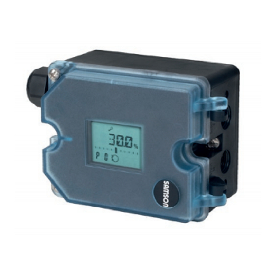
- Page 1 Series 3725 Electropneumatic Positioner Type 3725 Fig. 1 · Type 3725 Positioner Mounting and Operating Instructions EB 8394 EN (1300-1621) Firmware version 1.0x Edition February 2012...
- Page 2 Definitions of the signal words used in these instructions WARNING! NOTICE indicates a hazardous situation which, if not indicates a property damage message. avoided, could result in death or serious injury. Note: Supplementary explanations, information and tips EB 8394 EN...
-
Page 3: Table Of Contents
Contents Contents Page Safety instructions ......6 Article code ......7 Design and principle of operation. - Page 4 Contents 7.12 Faults ....... . . 42 Code list ....... 43 Maintenance .
- Page 5 Firmware revisions Firmware revisions 1.02 (previous) 1.03 (new) Internal revisions EB 8394 EN...
-
Page 6: Safety Instructions
Safety instructions Safety instructions For your own safety, follow these instructions concerning the mounting, start up and opera- tion of the positioner: The positioner is to be mounted, started up or operated only by trained and experi- enced personnel familiar with the product. According to these Mounting and Operating Instructions, trained personnel refers to individuals who are able to judge the work they are assigned to and recognize possi- ble dangers due to their specialized training, their knowledge and experience as well... -
Page 7: Article Code
Article code Article code Type 3725- Positioner x x x 0 0 0 0 0 0 0 9 9 9 9 With LCD and autotune, 4 to 20 mA reference variable Explosion protection* Without 0 0 0 II 2 G Ex ia IIC T4 acc. to ATEX 1 1 0 0 Other approvals in preparation EB 8394 EN... -
Page 8: Design And Principle Of Operation
Design and principle of operation Design and principle of The pneumatic air capacity booster (7) and the pressure regulator (8) are supplied with operation supply air. The output signal pressure supplied by the The electropneumatic positioner is mounted booster can be limited to 2.4 bar by soft- on pneumatic control valves. - Page 9 Design and principle of operation Control valve 10 Volume restriction AMR sensor 11 Display A/D converter Microcontroller D/A converter i/p converter Air capacity booster Pressure regulator Fixed restriction Fig. 2 · Functional diagram EB 8394 EN...
-
Page 10: Technical Data
Technical data Technical data Type 3725 Positioner Travel, adjustable Direct attachment to Type 3277 Actuator: 3.75 to 30 mm Attachment acc. to IEC 60 534-6-1 (NAMUR): 3.75 to 50 mm Attachment to Type 3372 Actuator: 15/30 mm Attachment to rotary actuators: 24 to 100°... - Page 11 Technical data Materials Housing Polyphthalamide (PPA) Cover Polycarbonate, transparent External parts Stainless steel 1.4571 and 1.4301 Cable gland Polyamide, black, M20 x 1.5 Weight Approx. 1.0 kg EB 8394 EN...
-
Page 12: Attachment To The Control Valve - Mounting Parts And Accessories
3. Connect the electrical power 4. Perform the start-up settings The positioner is suitable for the following types of attachment: Direct attachment to SAMSON Type 3277 Actuator Attachment to actuators according to IEC 60534-6 (NAMUR) Attachment to Type 3372 Linear Actua- tor (V2001 Valve Series) Fig. - Page 13 [cm²] [mm] Min. Travel Max. 15.0 120/240/350 21.2 355/700 10.6 30.0 Attachment according to IEC 60534-6 (NAMUR) SAMSON Type 3271 Actuator Travel of other valves [mm] Required Assigned lever pin position Actuator size Rated travel min. max. [cm²] [mm] 3.75 10.6...
-
Page 14: Direct Attachment
Attachment to the control valve – Mounting parts and accessories Direct attachment 4. 15 mm travel: Keep the follower pin (2) at lever M (1) on the back of the 4.1.1 Type 3277-5 Actuator positioner in the pin position 35 (deliv- ered state). - Page 15 Attachment to the control valve – Mounting parts and accessories Lever Symbols Disk spring Switchover plate (9) Follower pin Actuator stem Follower clamp extends Screw Stopper Connecting plate Attachment left Attachment right Seal rings Pressure gauge Actuator stem bracket retracts Press.
- Page 16 Attachment to the control valve – Mounting parts and accessories Additional solenoid valve If a solenoid valve is additionally mounted onto the actuator, the signal pressure port at the back of the positioner must be sealed. To do this, unscrew the screw located in the middle hole (screw in park position) and screw it into the signal pressure port to seal Screw plug (4)
-
Page 17: Type 3277 Actuator
Attachment to the control valve – Mounting parts and accessories 4.1.2 Type 3277 Actuator Refer to Table 2 on page 26 for the required mounting parts as well as the accessories with their order numbers. Note the travel table on page 13! Note: The actuators with 240 to 700 cm²... - Page 18 Attachment to the control valve – Mounting parts and accessories Actuators with 240 to 700 cm² the actuator with fail-safe action "Actua- tor stem extends" or "Actuator stem re- The positioner can be mounted either on the tracts". If necessary, remove the three left or right side of the yoke.
- Page 19 Attachment to the control valve – Mounting parts and accessories Lever Disk spring Follower pin Follower clamp Cover Connection block 12.1 Screw 12.2 Stopper or connection for external piping Formed seal Gasket 10 15 1 2 3 View A Ansicht A SUPPLY 12.1 12.2...
-
Page 20: Attachment According To Iec 60534-6
Attachment to the control valve – Mounting parts and accessories Attachment according to IEC 60534-6 The positioner is attached to the control valve with a NAMUR bracket (10). Refer to Table 3 on page 26 for the required mounting parts as well as the accessories with their order numbers. - Page 21 Attachment to the control valve – Mounting parts and accessories 14.1 Lever Disk spring Follower pin Follower plate Connecting plate Seal rings Pressure gauge bracket Pressure gauge mounting kit Stem connector Bracket NAMUR bracket Screw Bolt 14.1 Screw Fig. 10 · Attachment according to IEC 60534-6 (NAMUR) EB 8394 EN...
- Page 22 Attachment to the control valve – Mounting parts and accessories EB 8394 EN...
-
Page 23: Attachment To Type 3372 Actuator (V2001)
Attachment to the control valve – Mounting parts and accessories Attachment to Type 3372 Actuator (V2001) The Type 3725 Positioner is already in- cluded in the scope of delivery for V2001 valve series (Type 3372 Actuator). The attachment is briefly described below to allow conversion work to be performed. -
Page 24: Attachment To Rotary Actuators
(1) so that it engages in the slot of Before attaching the positioner onto the the coupling wheel (4) with its follower SAMSON Type 3278 Rotary Actuator pin (see Fig. 13). It must be guaranteed (160 cm²) or VETEC Type S160 Actuator,... - Page 25 Disk spring 10.1 Screw Actuator shaft Adapter 10.1 10.1 10.1 Attachment to SAMSON Type 3278 Rotary Actuator Attachment according to VDI/VDE 3845, level 2 (160 cm²) or VETEC Type S160 Actuator Fig. 13 · Attachment to rotary actuators EB 8394 EN...
-
Page 26: Mounting Parts And Accessories
Attachment to the control valve – Mounting parts and accessories Mounting parts and accessories Table 1 · Direct attachment to Type 3277-5 Actuator (see section 4.1) Order no. Mounting parts Mounting parts for actuators 120 cm² or smaller 1402-0239 Accessories for Switchover plate for Type 3277-5xxxxxx.01 Actuator 1400-6822 the actuator... - Page 27 Mounting parts Attachment according to VDI/VDE 3845 (level 2*), 20 mm shaft height 1402-0243 Attachment according to VDI/VDE 3845 (level 2*), 30 mm shaft height 1402-0244 Attachment to VETEC Type S160 Actuator or SAMSON Type 3278 Rotary 1402-0294 Actuator, 160 cm² (level 2*) G ¼...
-
Page 28: Connections
Connections Connections chamber of the actuator, depending on the actuator's fail-safe action "Actuator stem ex- tends" or "Actuator stem retracts". Pneumatic connections For rotary actuators, the manufacturer's specifications for connection apply. NOTICE The threaded connections in the positioner 5.1.1 Signal pressure gauges housing are not designed for the direct con- nection of pneumatic fittings! To monitor the supply air (Supply) and sig-... -
Page 29: Electrical Connections
Connections Electrical connections d = Seat diameter [cm] Dp = Differential pressure across the valve [bar] DANGER! A = Actuator diaphragm area [cm²] Risk of electric shock and/or = Upper bench range value [bar] the formation of an explosive atmosphere! If there are no specifications, calculate as –... - Page 30 Connections Selecting cables and wires: Cable entries Observe Clause 12 of EN 60079-14: 2008 The M20 x 1.5 cable gland is designed for when installing intrinsically safe circuits. a clamping range of 6 to 12 mm. The Subclause 12.2.2.7 applies when run- The cage clamp terminals hold wire ning multi-core cables containing more than cross-sections of 0.2 to 1.5 mm²...
- Page 31 Connections Accessories: Plastic cable gland M20 x 1.5: – Black Order no. 8808-1011 – Blue Order no. 8808-1012 mA control signal Fig. 15 · Electrical connections EB 8394 EN...
-
Page 32: Operation
Operation Operation NOTICE Any parameter code settings that have been Three capacitive keys and a LCD are used to changed are first saved in a non-volatile operate the positioner. memory after the display has returned to the To adapt the air capacity, the volume restric- display with status indication. -
Page 33: Start-Up - Settings
Start-up – Settings Volume restriction Q Start-up – Settings The volume restriction is used to adapt the WARNING! air delivery to the actuator size. Two fixed Do not perform a start-up while the process settings are possible depending on how the is running. -
Page 34: Enabling Configuration
Start-up – Settings Display after connecting the electrical sig- Press until OPEN appears on the display. Press to confirm unlocking. fault indication icon and S (fail-safe position) appear on the display when the WARNING! positioner has not yet been initialized. The During start-up the actuator stem moves. -
Page 35: Setting The Volume Restriction Q
Start-up – Settings Setting the volume restriction Adapting the display The data representation on the positioner display can be turned by 180°. If the displayed data appear upside down, proceed as follows: Press until Code P1 appears. Press to confirm the selected code. P1 blinks. -
Page 36: Entering The Opening Direction
Start-up – Settings Entering the opening the valve is closed and 100 % when the valve is open. direction If necessary, the direction of action can be AIR TO OPEN/ATO applies to a valve changed either before or after initialization. opening as the signal pressure increases. -
Page 37: Setting Other Parameters
Start-up – Settings Setting other parameters The following table lists all the parameter codes and their default settings. If you want to change the default setting of a parameter, proceed in the same manner as previously described. Note: The selected parameter code remains active until you change the setting or exit the parameter code. -
Page 38: Initialization
Start-up – Settings Initialization Initialization has started, the display blinks! During initialization the positioner adapts it- self optimally to the friction conditions and Note: The time required for the initialization the signal pressure required by the control procedure depends on the actuator transit valve. -
Page 39: Zero Calibration
Start-up – Settings Canceling initialization Zero calibration The initialization can be canceled by press- In case of inconsistencies in the closing posi- tion of the valve, e.g. with soft-sealed plugs, it might be necessary to recalibrate zero. Enable configuration (refer to section 7.1). Canceling initialization Start the zero calibration by activating Code P16 as follows:... -
Page 40: Manual Mode
Start-up – Settings Canceling zero calibration 7.10 Manual mode The zero calibration can be canceled by The valve position can be moved as follows pressing using the Manual mode function: Enable configuration (refer to section 7.1). Press until Code P17 appears. Press for six seconds, the display counts down 6-5-4-3-2-1. -
Page 41: Reset
Start-up – Settings 7.11 Reset system deviation between the manual and automatic set point while manually moving the valve in Code P17 . The positioner is in closed-loop operation after the initialization has been successfully The manual set point is adjusted in steps of 0.1 %. -
Page 42: Faults
Start-up – Settings 7.12 Faults The nominal range (Code P4 ) must be changed and the positioner re-initialized to On the occurrence of a fault, the fault remedy this problem. indication icon appears at the bottom of the display. Reset error codes If the fault indication icon appears after a The error codes E0 and E8 can be reset as parameter code setting has been changed,... -
Page 43: Code List
( P3 = 90°) Linear Equal percentage Reverse equal percentage SAMSON butterfly valve, linear SAMSON butterfly valve, equal percentage VETEC rotary plug valve, linear VETEC rotary plug valve, equal percentage Segmented ball valve, linear Segmented ball valve, equal percentage EB 8394 EN... - Page 44 Code list P6 * Reference variable For split-range operation [4...20 mA] SRLO – low range 4 to 11.9 mA SRHI – high range 12.1 to 20 mA SRLO/SRHI P7 * w/x Direction of action of the reference variable w to the travel/rota- [>>] /<>...
- Page 45 Code list Reset Parameters are reset to their default setting. The positioner can only return to closed-loop operation after it has be re-initialized. Enable configuration Enable configuration to change parameter settings. This function is automatically canceled when none of the keys are not pressed within three minutes.
- Page 46 Recommended action Reset error code (see section 7.12). Check positioner mounting and re-initialize the positioner. Software Internal software error Return positioner to SAMSON AG for repair. Hardware Internal device error Recommended action Return positioner to SAMSON AG for repair. EB 8394 EN...
-
Page 47: Maintenance
Maintenance Maintenance side hazardous areas, test the devices ac- cording to the specifications for servicing The positioner does not require any mainte- explosion-protected devices. nance. There are filters with a 100 m mesh size in the pneumatic connections for supply and output which can be removed and cleaned, if required. -
Page 48: Dimensions In Mm
Dimensions in mm Dimensions in mm M 20x1.5 157.5 62.50 Fig. 18 · Dimensional drawing of Type 3725 EB 8394 EN... -
Page 49: Fixing Levels According To Vdi/Vde 3845 (September 2010)
Dimensions in mm 11.1 Fixing levels according to VDI/VDE 3845 (September 2010) Level 2 (bracket surface) Level 1 (actuator surface) Actuator ØD Dimensions in mm Size Æd ÆD * 5.5 for M5 5.5 for M5 Flange type F05 according to DIN EN ISO 5211 EB 8394 EN... -
Page 50: Test Certificates
EB 8394 EN... - Page 51 EB 8394 EN...
- Page 52 EB 8394 EN...
- Page 53 EB 8394 EN...
- Page 54 EB 8394 EN...
- Page 55 EB 8394 EN...
- Page 56 SAMSON AG · MESS- UND REGELTECHNIK Weismüllerstraße 3 · 60314 Frankfurt am Main · Germany Phone: +49 69 4009-0 · Fax: +49 69 4009-1507 EB 8394 EN Internet: http://www.samson.de...
Need help?
Do you have a question about the 3725 series and is the answer not in the manual?
Questions and answers