Samson 3780 Mounting And Operating Instructions
Hart positioner
Hide thumbs
Also See for 3780:
- Mounting and operating instructions (76 pages) ,
- Mounting and operating instructions (76 pages)

Related Manuals for Samson 3780


Summary of Contents for Samson 3780
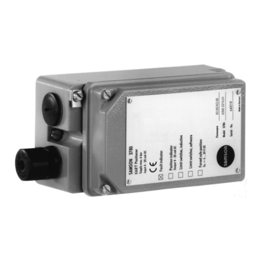
- Page 1 HART Positioner Type 3780 Fig. 1 ⋅ Type 3780 Mounting and operating instructions EB 8380-1 EN Firmware R 2.22/K 2.23 Edition February 2003...
-
Page 2: Table Of Contents
Contents Contents Page Design and principle of operation ..... . 10 Options ........10 Communication . - Page 3 Proper shipping and appropriate storage are assumed Note: Devices with the CE mark meet the requirements specified in the Directive 94/9/EC and the Directive 89/336/EEC. The Declaration of Conformity can be viewed and downloaded on the Internet at http://www.samson.de. EB 8380-1 EN...
- Page 4 Modifications of positioner firmware Modifications of positioner firmware in comparison to previous version Former For more details on the listed parameters, please also refer to the list of parameters in chapter 8. Positioner R 1.41 R 2.01 Parameters: Operating direction Direction of action The reference variable (w) is not assigned to the output signal pressure (y) anymore, but to the travel/angle of rotation (x).
- Page 5 Modifications of positioner firmware Former Positioner 2.02 R 2.11 Parameters: The minimum pulses for filling and venting are determined for Minimum pulse the travel ranges 0 to 20 %, 20 to 80 % and 80 to 100 %. The filling/venting minimum pulses are no longer determined during initialization.
- Page 6 Modifications of positioner firmware Changing the type of initialization from "maximum range" to End position when w </> "nominal range" causes: End position at < End position at > 125 % Changing the type of initialization from "nominal range" to "maximum range"...
- Page 7 If this option is activated using the switch, the positioner settings cannot be written over by HART communication. See chapter 4.1 for more details on the write protection switch. Model index 3780-x...x. 03 and upwards are suitable for the extended valve diagnosis using the TROVIS-EXPERT software.
- Page 8 Technical data Positioner Rated travel, adjustable Direct attachm. 5 to 30mm Attachment acc. to IEC 60534-6 (NAMUR), 5 to 255 mm or 30 to 120° C Reference variable Two-wire connection, signal range 4 to 20 mA, span 4 to 16 mA Min.
- Page 9 Versions Communication Hardware requirements SAMSON’s TROVIS-VIEW Operator Interface (see Data Sheet T 6661 EN) or handheld communicator, e.g. Type 275 by Rosemount Integration of other operator interfaces, e.g. DTM, are available Data transmission HART Field Communication Protocol Impedance in HART frequency range: receive: 350 to 450 Ω; send: approx. 115 Ω...
-
Page 10: Design And Principle Of Operation
Design and principle of operation Forced venting function 1. Design and principle of operation The positioner is controlled via a 6 to The positioner essentially consists of an in- 24 V signal, causing the signal pressure ductive, non-contact displacement sensor to be applied to the actuator. -
Page 11: Communication
Design and principle of operation You can configure and operate the posi- 1.2 Communication tioner either via HART-compatible, hand- For communication, the positioner is held communicator or via PC, using an FSK equipped with an interface for the HART modem and an RS 232 interface. protocol (Highway Addressable Remote After mechanically resetting the positioner Transducer). - Page 12 Design and principle of operation The positioner is supplied with a standard Operating software configuration applying to a valve with TROVIS-VIEW 15 mm rated travel, which is designed for for devices with firmware K 2.11 or integrated positioner attachment. higher, Data Sheet T 6661 EN An individual configuration needed to IBIS adapt the positioner to deviating actuators...
-
Page 13: Attachment To The Control Valve
The positioner does not have a venting The positioner can be attached either di- plug. Instead the air is exhausted via vent- rectly to a SAMSON Type 3277 Actuator, ing plugs on the mounting parts (see also or according to Namur (IEC 60534-6), to Fig. -
Page 14: Direct Attachment To Type 3277 Actuator
Attachment to the control valve tracts" has to correspond to the respec- 2.1 Direct attachment to Type 3277 tive actuator version used. If not, Actuator remove the two fastening screws and the switch plate, turn the switch plate by For the selection of the required mounting 180°... - Page 15 Attachment to the control valve Actuator stem extends Actuator stem retracts Internal signal Signal pressure pressure connection connection via piping Connection block Side view of connection Venting block with switch plate 1.2 Clamp D 1 Lever Lever Distance plate Cover "Actuator stem extends"...
- Page 16 Attachment to the control valve 7. Mount the positioner so that the hole in the distance plate (15) matches the seal located in the hole of the actuator yoke. 8. Align the switchover plate with the corresponding symbol for left attach- ment according to the marking and screw tight onto the actuator yoke.
- Page 17 Attachment to the control valve Table 1 Actuator size Mounting kit Required lever with associated clamp and distance plate Order no. D1 (33 mm in length with clamp 17 mm in height) 120 (G1/4) 1400-6790 120 (NPT 1/4) 1400-6791 D1 (33 mm in length with clamp 17 mm in height) 240 and 350 1400-6370 D2 (44 mm in length with clamp 13 mm in height)
-
Page 18: Attachment According To Iec 60534-6 (Namur)
Attachment to the control valve Control valve with cast yoke 2.2 Attachment according to IEC 60534-6 (NAMUR) 1. Use countersunk screws to screw the plate (20) to the coupling which con- nects the plug and actuator stem. With For the selection of the required mounting 2,100 and 2,800 cm actuators, use parts, refer to Tables 4 and 5 (page 21). - Page 19 Attachment to the control valve Mounting position Attachment to NAMUR rib 24 25 21 20 Attachment to rod-type yoke Lever N1, N2 Plate Clamp Clamping plate Screw Pointer Shaft Lever of positioner Coupling pin Lock nut Bracket Studs Plate Nuts Mounting bracket Fig.
-
Page 20: Presetting The Valve Travel
Attachment to the control valve 2.2.2 Presetting the valve travel 1. Adjust the shaft (25) in the adapter housing so that the black pointer (24) is aligned with the casted marking on the adapter housing. 2. Screw tight clamping plate (22) in this position, using a screw (23). - Page 21 Attachment to the control valve NAMUR attachment Control valve Travel in mm With lever Order no. Table 4 7.5 to 60 N1 (125 mm) 1400-6787 NAMUR mounting kit Valve with cast yoke 30 to 120 N2 (212 mm) 1400-6789 20 to 25 1400-6436 Parts illustrated in Fig.4 Valve with...
-
Page 22: Attachment To Rotary Valves
(fixing level 1 VDI/VDE 3845) more details. and screw tight. If the positioner is attached to a SAMSON 2. Align the cam disk (40) and scale as de- Type 3278 Rotary Actuator, the air ex- scribed in chapter 2.3.3 and fasten hausted from the positioner is admitted to tight. - Page 23 Attachment to the control valve Attachment to SAMSON Type 3278 Attachment acc. to VDI/VDE 3845 (NAMUR) 41 40 39 Positioner Venting Intermediate piece Lever w. cam follower roll 0˚ Adapter Attachment to Transmission lever reversing amplifier Screws Scale Cam disk...
-
Page 24: Aligning And Mounting The Cam Disk
Attachment to the control valve 2.3.3 Aligning and mounting of With actuators with fail-safe position "Valve the cam disk OPEN", the maximum signal pressure must be applied to the actuator before aligning In rotary actuators with spring-return mech- the cam disk. anism, the built-in actuator springs deter- With springless actuators, the supply air mine the fail-safe position and the direction... - Page 25 Control valve opens clockwise Control valve opens counterclockwise Fig. 6 ⋅ Aligning the cam disk Rotary actuators (Complete mounting parts, but without cam disks) Table 6 SAMSON Type 3278 Actuator Attachmt. acc. to VDI/VDE 3845 Attachment to Masoneilan actuator Actuator Actuator Camflex I...
-
Page 26: Reversing Amplifiers For Double-Acting Actuators
Reversing amplifier for double-acting actuators Signal pressure connections 2.3.4 Reversing amplifier for double-acting actuators : Output A leading to the signal press- ure connection at the actuator which opens For the use with double-acting actuators, the valve when the pressure increases the positioner must be fitted with a reversing : Output A leading to the signal press-... - Page 27 Reversing amplifier for double-acting actuators From the positioner Output 38 Supply 9 Reversing amplifier Control signals 1.1 Special screws to the actuator 1.2 Gasket 1.3 Special nuts 1.4 Rubber seal 1.5 Plug 1.3 1.2 Fig. 7 ⋅ Mounting a reversing amplifier EB 8380-1 EN...
-
Page 28: Connections
Connections 3. Connections 2...3mm 3.1 Pneumatic connections The air connections are either NPT 1/4 or G 1/4 tapped holes. The customary fittings for metal and copper tubes or plastic hoses can be used. Throttle with filter NOTE (1790-6121) The supply air has to be dry and free from oil and dust. -
Page 29: Supply Air Pressure
Connections 3.1.2 Supply air pressure 3.2 Electrical connections The required supply air pressure depends As far as the electrical installation of on the bench range and the actuator’s fail- the device is concerned, the relevant safe action. The bench range is registered national regulations governing the on the nameplate either as spring range or installation of electrical equipment... - Page 30 Connections Caution! If the poles are connected incor- Note on the selection of cables and wires: To run several intrinsically safe circuits in a rectly, just 1.4 V is sufficient to reach the multi-core cable, read paragraph 12 of EN static destruction limit of 500 mA.
-
Page 31: Switching Amplifiers
Order no. 1400-6782 Adapter PG 13.5 on 1/2" NPT: Metallic Order no. 1400-7109 Blue finish Order no. 1400-7110 Model index 3780-x...x. 02 and upwards Cable gland M20 x 1.5: Black plastic Order no. 1400-6985 Blue plastic Order no. 1400-6986 Adapter M20 x 1.5 on1/2" NPT: Aluminum powder-coated Order no. -
Page 32: Establishing Communication
Connection of an FSK bus always range of 1 to 15. requires interfacing of isolating amplifiers. Connection in non-hazardous areas Communicator or 2nd FSK modem 4 to 20 mA 3780 Controller/ control station FSK modem PC RS 232 Non-haz. area Hazardous area PC RS 232... - Page 33 Connections Note: Communication faults may occur when the process controller/control station output is not HART-compatible. For adaptation, the HART box, order no. 1170-1349, can be in- stalled between output and communication interface. At the HART box a voltage of 1 V is released (≥50 Ω...
-
Page 34: Operation
Operation When it is activated (position 1), the posi- 4. Operation tioner settings are write-protected so that they cannot be overwritten by the HART CAUTION protocol. If you want to change the settings Before taking the positioner into ope- via communication, set the switch to 0 posi- ration, carefully move the control val- tion. -
Page 35: Default Setting
Operation 4.3 Default setting 4.3.2 Initialization All parameters are set to default values. See After the electric reference variable and the chapter 8 for a description of parameters. auxiliary supply pressure have been con- nected to the positioner, the initialization process can be started. - Page 36 Operation The initialization is completed when the po- Fail-safe position "Actuator stem ex- tends" (FA): sitioner takes on the position predetermined Direction of action: increasing/increas- by the reference variable. ing (>>), the globe valve opens with in- creasing reference variable NOTE Final position at a reference variable After the positioner has been initialized suc-...
-
Page 37: Adjusting Inductive Limit Switches
Operation The electric calibration has been completed Move the valve to the switching position when the positioner takes on the position and adjust the tag of the required limit predetermined by the reference variable. switch GW1 or GW2 by turning the re- lated adjustment screw until the switching 4.4 Adjusting inductive limit switches point is reached. -
Page 38: Maintenance
Maintenance 5. Maintenance The positioner is maintenance-free. The pneumatic connection 9/Supply fea- tures a sieve with 100 µm mesh size. If re- quired, the filter can be unscrewed and cleaned. The maintenance instructions for any up- stream air pressure reducing stations for supply air must be observed. -
Page 39: Summary Of Parameters
Summary of parameters 7. Summary of parameters The list of parameters describes - in alphabetical order - all parameters of the Type 3780 Po- sitioner that can be transferred via HART communication and displayed or modified on a PC, a handheld communicator, or a similar device. - Page 40 Summary of parameters – Minimum control pulses – Minimum transit time on/off – Initialization cycle Device settings Configuration – Reference variable range – Final position with reference variable below preset value – Final position with reference variable above preset value –...
- Page 41 Summary of parameters – State software limit switches GW1/GW2 – Forced venting function Diagnostics – Device status (control loop monitoring, zero point monitoring, etc.) – Total valve travel – Limit value total valve travel – Error monitoring tolerance band/lag time –...
-
Page 42: List Of Parameters
VDI / VDE 3845 (NAMUR) is possible. States: Integral - Type of attachment in combination with a SAMSON Type 3277 Linear Actuator. NAMUR - Type of attachment according to IEC 60534-6 (NAMUR). Default (coldstart) value:... - Page 43 List of parameters Creation of assignments between the reference variable and valve travel/angle range. Characteristic When the equal percentage characteristic is selected, this characteristic is copied in the user-defined characteristic, overwriting the previously entered user-defined characteristic. The control loop is interrupted (for approx. 3 seconds) while the characteristic is internally transmitted.
- Page 44 List of parameters Caution: Since the actuator will automatically be filled (loaded with air) or vented (exhausted) when this function is executed, the control valve moves to its absolute end position. Constraints specified in the function "travel range" or "travel limit" are inapplicable here.
- Page 45 List of parameters States: No/Yes Default (coldstart) value: Fault message for controller in special function (zero calibration, initialization, test Fault alarm: functions). Special function States: No/Yes Default (coldstart) value: Fault alarm: Total valve Fault alarm whenever the limit value for the total valve travel is exceeded. travel exceeded States: No/Yes...
- Page 46 List of parameters Range: 0.0 % to 120 % Default (coldstart) value: 2.0 % Limit value alarm referring to travel/angle range, determined by the software from the Limit switch signal of the travel (displacement) pick-up. (Switching hysteresis 1%). Software GW2 Range: 0.0 % to 120 % Default (coldstart) value:...
- Page 47 List of parameters An arrow is located on the cover plate of the positioner, which is used for alignment on the Mounting position (linear actuator) actuator. This arrow must either point toward the actuator (direct attachment) or away from the actuator (NAMUR attachment). Exception: Control valves for which the seat is solely closed by a retracting actuator stem.
- Page 48 List of parameters Range: 0 to 15 Default (coldstart) value: For IBIS devices → bus address Type number of the positioner Positioner type number Position transmitter Indicates whether the option position transmitter is installed. States: Not installed/Installed Product number Manufacturer’s product number of the positioner. Length: 16 characters. Proportional-action coefficient KP_Y1 for supply air, KP_Y2 for exhaust air.
- Page 49 List of parameters Adaptation of the minimum pulses in order to optimize the control algorithm for the system Pulse adaptation comprising positioner, actuator and valve. In normal control mode the parameter should be set to "Automatic". Disable this parameter when tuning the control parameters. For R 1.20 and upwards, the pulse adaptation is internally set to "Automatic".
- Page 50 List of parameters State of the software limit switch GW1 or GW2. State of software limit switch GW1/ GW2 Off, ≤1 mA States: On, ≥3 mA Test of fault alarm Functional test of the fault alarm output by activating it three times. (special function) Test of position transmitter Test of the optional position transmitter by specifying values in % (only when the software...
- Page 51 List of parameters Pin position of the positioner lever. See marking on the positioner lever. Transmission pin position Only for attachment to linear actuator acc. to NAMUR. States: Default (coldstart) value: Travel/angle limit Lower limitation of valve travel/angle to the entered value. The characteristic is not adapted. lower Range: –20.0 % to 99.9 % of the travel/angle range...
- Page 52 List of parameters When this option is activated, the device data can only be read, but they cannot be Write protection overwritten. The only way to activate the write protection is using the switch installed on the device. States: Activated/deactivated Zero calibration Zero correction with valid mechanical zero point.
-
Page 53: Error Messages And Diagnostics
Error messages and diagnostics 9. Error messages and diagnostics Information/alerts 9.1.1 Device settings changed 9.1.2 Insufficient power supply 9.1.3 Warmstart completed 9.1.4 Coldstart completed 9.1.5 Choose "MANUAL" mode 9.1.6 Parameter not supported 9.1.7 Limit value of total valve travel exceeded 9.1.8 Zero adjustment aborted 9.1.9... -
Page 54: Information/Alerts
Error messages and diagnostics During the initialization cycle, the Type 3780 HART Positioner offers the best possibilities for diagnosis. In the automatic mode, detailed tests are carried out in order to check the attach- ment situation and the positioner’s reaction while taking the preset or entered data into ac- count. -
Page 55: Error Messages
Error messages and diagnostics 9.1.6 Parameter not supported After downloading to the positioner, the positioner intelligence replies that this parameter is unknown. This message can occur with older firmware versions. The device is automatically reset after acknowledgement. 9.1.7 Limit value of total valve travel exceeded The current value which is stored after 1024 double strokes and protected against power failure lies above the limit value entered or preset via [Device data →... - Page 56 Error messages and diagnostics 9.2 Error messages 9.2.1 Communication fault This message is displayed when the HART communication is interrupted. Possible sources of error: – Auxiliary power too low or power failure – FSK modem not properly connected Communication (for example COM1) configured incorrectly [Options → Con- –...
- Page 57 Error messages and diagnostics – Impurities between valve plug/seat The device is reset after the zero adjustment has been carried out effectively. 9.2.4 Zero calibration erroneous, mechanical readjustment necessary The value determined during electric zero calibration exceeds the permissible tolerance of ±5 % by the internal absolute value for the detection of measured values.
- Page 58 Error messages and diagnostics Characteristic fault In case a characteristic fault (chapters 9.2.9 to 9.2.11) occurs, the characteristic is automat- ically switched from user-defined to linear after downloading data to the positioner. 9.2.9 Erroneous characteristic This message is generated when errors are recognized during transmission of the charac- teristic.
-
Page 59: Error Messages During Initialization Without Abortion
Error messages and diagnostics 9.2.16 Communication data memory erroneous A memory block in the RAM/EEPROM area cannot be written. Repair required. 9.2.17 Checksum error communication data memory This message is generated when, during cyclic check, a memory block in the communication parameter area has been modified without verification. -
Page 60: Error Messages During Initialization With Abortion
Error messages and diagnostics 9.3.2 Air leakage of pneumatic system The actuator stalls for a few seconds when the duty cycle is being determined. This time is used by initialization to check the pneumatic system for leaks. If the control valve moves more than 9.3 % from this resting position within 7 seconds, initialization is aborted with this error message. - Page 61 Error messages and diagnostics 9.4.2.2 Zero calibration error The determined zero point does not lie within the acceptable tolerance limit of max. ±5 % by the internal absolute value for the detection of measured values. To eliminate this error, mechanical zero must be adjusted. The yellow pointer of the displace- ment sensor must then be approximately in alignment with the marking on the cover plate.
-
Page 62: Dimensional Diagram
Dimensional diagram Pneumatic connections G 1/4 or NPT 1/4 M20 x 1.5 Direct attachment Output (36) 30.5 Supply (9) Fulcrum of Attachment with intermediate actuator shaft piece for rotary actuators Attachmt acc. to IEC 60534-6 with adapter housing Output 1 (A1) 28.5 Output 2 (A2) Supply (Z) -
Page 63: Type Examination Certificates
EB 8380-1 EN... - Page 64 EB 8380-1 EN...
- Page 65 EB 8380-1 EN...
- Page 66 EB 8380-1 EN...
- Page 67 EB 8380-1 EN...
- Page 68 EB 8380-1 EN...
- Page 69 EB 8380-1 EN...
- Page 70 EB 8380-1 EN...
- Page 71 EB 8380-1 EN...
- Page 72 EB 8380-1 EN...
- Page 73 EB 8380-1 EN...
- Page 74 EB 8380-1 EN...
- Page 75 EB 8380-1 EN...
- Page 76 SAMSON AG ⋅ MESS- UND REGELTECHNIK Weismüllerstraße 3 ⋅ 60314 Frankfurt am Main ⋅ Germany Phone +49 69 4009-0 ⋅ Fax +49 69 4009-507 EB 8380-1 EN Internet: http://www.samson.de...
Need help?
Do you have a question about the 3780 and is the answer not in the manual?
Questions and answers