
Related Manuals for Axminster PROFESSIONAL AP530WL


Summary of Contents for Axminster PROFESSIONAL AP530WL
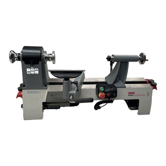
- Page 1 Code 111887 Original Instructions AP530WL Bench Lathe 230V AT: 17/11/2024 BOOK VERSION: 1...
-
Page 2: Table Of Contents
Table of contents 1. Safety …………………………………………………………………………………………………………………..1 1.1 Safety instructions for general machinery ....................1 1.2 Intended use .............................. 2 1.3 Safety instructions for wood turning lathe ....................3 1.4 Safety devices ............................4 1.5 Reasonably foreseeable misuse ........................ 4 1.6 Possible dangers caused by the wood turning lathe.................. 4 1.7 Safety check .............................. - Page 3 4.3 Turning tools ............................17 5. Maintenance ..............................19 5.1 Schedule ..............................19 5.2 Cleaning ..............................19 5.3 Lubrication ............................... 19 5.4 Tensioning and replacing belt ........................20 5.4.1 Tension belt ............................20 5.4.2 Replacing belt ........................... 20 5.5 Replacing brushes (FOR MC1421VDA ONLY) ..................20 6.
-
Page 4: Safety
1. Safety This operating instructions ▲explains the meaning and use of the warning notes included in the operating instructions ▲points out the dangers that might arise for you or others if these instructions are not observed. ▲informs you how to avoid dangers. In addition to these operation instructions, please observe ▲the applicable laws and regulations ▲the statutory provisions for accident prevention... -
Page 5: Intended Use
For your own safety, read instruction manual before operating the machine. Learn the machine’s application and limitations as well as the specific hazards peculiar. Always wear approved safety glasses or a face shield when operating or observing machinery to reduce the risk of eye injury or blindness from flying particles Everyday eyeglasses are not approved safety glasses. -
Page 6: Safety Instructions For Wood Turning Lathe
1.3 Safety instructions for wood turning lathe Serious injury or death can occur from getting entangled in, crushed between, or struck by rotating parts on a lathe! Rotating workpieces can come loose and strike operator or bystanders with deadly force if they are improperly secured, rotated too fast, or are not strong enough for the rotational forces required for turning. -
Page 7: Safety Devices
Commonly caused by poor workpiece selection/preparation, improper tool usage, or improper machine setup or tool rest adjustment. Use correct tool. Take light cuts, use low speeds, and firmly support SAFELY PERFORM tool with both hands. ROUGHING Sharp tools cut with less resistance than dull tools. Using dull tools USE SHARP TOOLS increases the risk of tool kickback or grabbing Always allow rotating workpiece to stop on its own. -
Page 8: Safety Check
machine operates under electrical voltage and currents and high speed. We have used design and safety engineering to minimize the health risk to personnel resulting from these hazards. If the machine is used and maintained by personnel who are not duly qualified, there may be a risk resulting from incorrect or unsuitable maintenance. -
Page 9: Technical Specification
2. Technical Specification The following information represents the dimensions and weight information and the manufacturer‘s approved machine data. 2.1 Specification Model Number AP530WL Motor Power 1100W/1400W DC brushless motor 60-720 Spindle RPM/50Hz 130-1700 300-3550 Spindle Thread M33X3.5 or other Spindle /Tailstock Taper No. -
Page 10: Assembly
3. Assembly The wood turning lathe is delivered pre-assembled. After unpacking, the lathe must be installed. Transport the wood turning lathe in its packing crate to a place near its final installation site before unpacking it. If the packaging shows signs of possible transport damage, take the necessary precautions not to damage the machine when unpacking. -
Page 11: Placement Location
give you a better appreciation for the proper care of your machine's unpainted surfaces. Basic steps for removing rust preventative: 1. Put on safety glasses. 2. Coat the rust preventative with a liberal amount of cleaner/degreaser, then let it soak for 5–10 minutes. -
Page 12: Initial Commissioning
3.6 Initial commissioning Once assembly is complete, test run the machine to ensure it is properly connected to power and safety components are functioning correctly. If you find an unusual problem during the test run, immediately stop the machine, disconnect it from power, and fix the problem BEFORE operating the machine again. -
Page 13: Setting Up The Face Plate
body is properly positioned. NOTE: There is a nut on the underside of tool rest body that needs to be tightened periodically to enable the tool rest body locking lever to tighten properly. 2. The small tool rest locking handle locks the tool rest in place. Loosen the handle to position the tool rest at the specific angle or height. -
Page 14: Tailstock Adjustment
3.7.4 Tailstock adjustment Loosen the tailstock locking lever and slide the tailstock along the lathe bed into the desired position. Retighten the locking lever. Loosen the quill locking handle just enough to unlock the tailstock quill. Turn the handwheel clockwise to advance the quill and counterclockwise to retract the quill. - Page 15 FOR MC1421VDA MC1421VDB FOR MC1421VF Always start at slower speeds for rough cuts and larger workpieces. Use faster speeds for refined cuts and detailed work. Set the suitable speed range for your operation by adjusting the belt position. Change the speed within a speed range using the speed adjustment knob.
-
Page 16: Speed Recommendations
panel to set the speed within your selected speed range. Use the forward/reverse switch to set the rotational direction. 3.7.8 Speed recommendations High range is best when turning a workpiece where a clean finish is required and only light cuts are made. -
Page 17: Spindle Turning Tips
Find center point of both ends of your workpiece ▲ by drawing diagonal lines from corner to corner across end of workpiece. Make a center mark by using a wood mallet and ▲ tapping point of spur center into center of workpiece on both ends. -
Page 18: Roughing Out Cut
and knowledgeable lathe users. The following operation instructions serves as a beginning point for some common lathe operations. Practice on scrap material to become familiarized with the operation process and make the necessary adjustments before working on your workpiece. 4.1.2 Roughing out cut Roughing out is the first step of the lathe operation, which uses the large roughing gouge tool to smooth out sharp corners to make the workpiece cylindrical. -
Page 19: Creating Coves
2. Using a small skew or spindle gouge, start in the center between the two cuts and cut down each side to form the bead. Roll the tool in the direction of the cut. 4.1.4 Creating coves Using a spindle gouge to create a cove. 1. -
Page 20: To Shape The Inside Of A Bowl Or Plate
plate as a template, mark the location of the mounting holes on the workpiece and drill pilot holes of the appropriate size. If the mounting screws on the face plate will interfere with the workpiece, a waste block can be used. - Page 21 Roughing gouge ▲ Mainly used for rough cutting, detail cutting, and cove profiles. The rough gouge is a hollow, double-ground tool with a round nose, and the detail gouge is a hollow, double-ground tool with either a round or pointed nose. Spindle gouge ▲...
-
Page 22: Maintenance
5. Maintenance This chapter contains important information about ▲ Inspection ▲ Maintenance ATTENTION! Properly performed regular maintenance is an essential prerequisite for operational safety, failure-free operation, a long service life of the wood lathe and the quality of the products which you manufacture. Installations and equipment from other manufacturers must also be in good condition. -
Page 23: Tensioning And Replacing Belt
5.4 Tensioning and replacing belt Most of the stretching will occur during the first 16 hours, but may continue with further use. If the lathe loses power while making a cut, the belt may be slipping and need tensioning. If the belt shows signs of excessive wear, or damage, replace it. - Page 24 To replace motor brushes: 1. Disconnect machine from power! 2. Use dime to unscrew and remove brush caps on front and rear of motor. 4. Use a ruler to measure wear of each carbon brush. If either brush is worn to less than 1/4" in length, replace both brushes.
-
Page 25: Troubleshooting
6. Troubleshooting 6.1 Motor& Electrical DRO ERROR CODE LIST (FOR MC1421VDA ONLY) ERROR CODE DESCRIPTION SOLUTION low voltage protection (20% lower than standard) check voltage, restart lathe high voltage protection (20% higher than standard) check voltage, restart lathe incorrect operation of reverse turn off main switch, restart lathe after the speed display showing "zero"... -
Page 26: Wood Lathe Operations
6.2 Wood lathe operations Symptom Possible Cause Possible Solution Bad surface 1. Dull tooling or wrong tool used for task. 1. Sharpen tooling, select correct tool for operation. finish. 2. Tool height is not 1⁄8" above spindle 2. Adjust tool rest so tool is 1⁄8" above spindle centerline. -
Page 27: Optional Accessories
7. Optional accessories Installing unapproved accessories may cause machine to malfunction, resulting in serious personal injury or machine damage. To reduce this risk, only install accessories recommended for this machine. 7.1 New extension bed The lathe is designed with three positions for installing the optional extension bed. When installed on the left side, the maximum swing over bed can reach to 16”... -
Page 28: Dimensions
7.1.1 Dimensions 7.1.1 Dimensions Consider anticipated workpiece sizes and additional space needed for auxiliary stands, work tables, or other machinery when establishing a location for this machine in the shop. Consider anticipated workpiece sizes and additional space needed for auxiliary stands, work tables, Below is the minimum amount of space needed for the machine with new extension bed when install or other machinery when establishing a location for this machine in the shop. -
Page 29: Part List For Mc1421Vdb
8.2 Part list for MC1421VDB 8. Diagram and part list PART NO. DESCRIPTION PART NO. DESCRIPTION 8.1 Diagram for MC1421VDB Handle sleeve Indexing pin Locking handle Screw Locking cam Bearing cover Elastic cylindrical pin Screw Locking screw Plastic Spacer Pressing plate Elastic retaining ring Motor base Spindle... -
Page 30: Wiring Diagram For Mc1421Vdb
Wiring diagram for MC1421VDB Please dispose of packaging for the product in a responsible manner. It is suitable for recycling. Help to protect the environment, take the packaging to the local amenity tip and place into the appropriate recycling bin. Only for EU countries Do not dispose of electric tools together with household waste material! In observance of European Directive 2002/96/EC on waste electrical and... - Page 32 The packaging is suitable for recycling. Please dispose of it in a responsible manner. EU Countries Only Do not dispose of electric tools together with household waste material. By law they must be collected and recycled separately. Axminster Tools, Axminster Devon EX13 5PH axminstertools.com...
Need help?
Do you have a question about the PROFESSIONAL AP530WL and is the answer not in the manual?
Questions and answers