
Related Manuals for Axminster AP508WL


Summary of Contents for Axminster AP508WL
- Page 1 Code 107657 Original Instructions AP508WL Woodturning Lathe AT: 208/02/2022 BOOK VERSION: 7...
-
Page 2: Eu Declaration Of Conformity
Wiring Diagram CE Certificate 29-30 Notes EU Declaration of Conformity Cert No: KS-20, KC-INV EU Declaration of Conformity Axminster Tool Centre Ltd This machine complies with the following directives: Axminster Devon EX13 5PH UK axminstertools.com 2006/42/EC EN 61000-6-4: 2007/A1:2011 2006/95/EC... -
Page 3: What's Included
What’s Included Quantity Item Part Model Number AP508WL Variable Speed Wood Lathe Tool Rest Extension Post Spanner Live Centre Push Rod Push Rod Tool Rest (Small) Tailstock Live Centre Alignment Centre 2MT 4 Prong Drive Centre 2MT Face Plate Tool Rest (Large) - Page 4 What’s Included...
-
Page 5: General Instructions For 230V Machines
General Instructions for 230V Machines The following will enable you to observe good working • Carry out a final check e.g. check the cutting tool practices, keep yourself and fellow workers safe and maintain is securely tightened in the machine and the correct your tools and equipment in good working order. -
Page 6: Specific Safety Instructions For Wood Turning Lathes
7. If your lathe has the facility to run in reverse, you must ensure of your work. Specification Code 107657 Model AP508WL Rating Professional Power 2.2kW 230V 1ph Speed 60-1,200, 100-2,200, 140-3,700 rpm... - Page 7 Assembly 2. Carefully remove the headstock, tailstock and tool rest banjo Important Notes and place safely aside, see fig 06-07-08. Please take some time to read the section entitled ‘Illustration NOTE: Before you remove the headstock assembly, first and Description’ to identify the various parts of your machine remove the Electronic inverter control box from the pallet so that you are familiar with the terminology we will use to by removing the two securing screws and place safely aside,...
- Page 8 Assembly Stand Assembly 1. Locate the two lathe stands (M) and the four adjustable feet (L). Screw the threaded feet into the pre-drilled holes to the base of the stands, see fig 09. Fig 09 2. Place the leg stands on their feet, locate the eight M10 bolts, spring washer/washers, see fig 10.
- Page 9 Assembly Hex screw Hex key 4. Make sure the lathe bed is thoroughly cleaned then replace the headstock banjo/tool rest and tailstock, replace the stop pinsto either end of the lathe bed, see fig 16-17-18-19. Fig 16-17-18-19 Main Control Box Electronic Inverter Control Box The main control box has a magnetic base enabling it to be Locate the inverter control box and two Hex screws.
- Page 10 Assembly Fig 27-28 Height mounting plates Lathe Bed Extension The extension bed (N) will increase the capacity of your lathe in three ways. The lathe can be used with the main bed either way around, this is because the extension bed (N) can be mounted either on the end of the main bed to extend the distance between centres, on the leg stand (M) to create a bigger turning diameter, or on a mounting plate machined onto the side of the main bed.
- Page 11 Assembly 2. Insert drive centre Morse taper (G) into the headstock Setup 3 ( mounted to side of the lathe bed) spindle and repeat the process for the live centre (I) into the The extension bed can be mounting to one side of the lathe tailstock barrel.
-
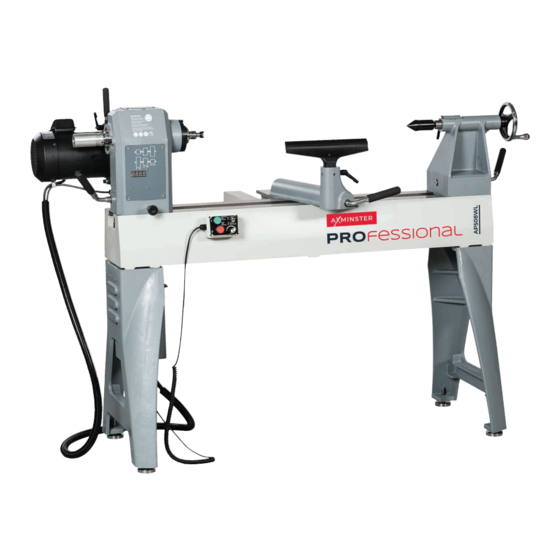
Page 12: Illustration And Parts Description
Illustration and Parts Description Motor locking handle Tailstock Tailstock Motor handle barrel lock Tool rest Four prong drive centre Tool rest lock Banjo lock handle Control box with magnetic base Lathe bed Stand Electronic inverter control box Setup 1 Flexible control box cord Adjustable foot Digital readout Headstock locking handle... - Page 13 Illustration and Parts Description Motor pulley access panel Motor and spindle pulleys (A), Drive belt (B) Pulley access panel Spindle locking pin with window with magnetic base M33 Spindle thread Motor Indexing assembly (A) Motor locking handle (B) Speed chart Spindle speed LED Indexing ring with 24 positions Spindle collar access hole to use in conjunc-...
- Page 14 Illustration and Parts Description The control box has a magnetic base enabling it to be positioned anywhere on the lathe. Forward and Reverse switch, (A), Speed (Green button) to turn ON and (Red button) to switch OFF Control Knob (B), enables you to increase or decrease the speed of the spindle Turn the switch to the (I) position to put Electronic inverter control box...
- Page 15 Illustration and Parts Description Setup 3 Four prong drive with a 2MT shaft (A) and Tailstock live centre with a 2MT tshaft (B) Setup 4...
- Page 16 Operating Instructions Rotating the Headstock The headstock can be swivelled a full 360˚ degrees with indexing stops every 45˚ degrees. To rotate the headstock lift up the Headstock locking lever (a) and pull the headstock pivot lock (b) out, see fig 39-40. Swivel the headstock around, you will here a click as the head engages in the first index stop at 45˚, see fig 41.
- Page 17 Operating Instructions Fig 48 Live Centre Nose Cone Removing the Faceplate The live centre features a removable front nose cone revealing 1. Locate the spindle locking pin (P), rotate the spindle until a small centring pin for turning small work. Removing the pin the machined hole on the shaft lines up with the spindle collar allows you to use the hollow live ring centre for holding your access hole.
-
Page 18: Mains Supply
Operating Instructions 3. To remove the centring pin, insert the live centre push rod (D) Fig 54-55 through the shaft and place the centre pin safely aside, see fig 51-52. Fig 51-52 Centre pin Fig 56-57 Indexing Facility DISCONNECT THE LATHE FROM THE MAINS SUPPLY! The Indexing ring is situated to the left side of the headstock which incorporates 24 positions at (10˚) segments. - Page 19 Operating Instructions Removing the Drive Centre To remove the drive centre from the spindle, locate the push rod (E), insert it through the index ring assembly and push the drive centre out, see fig 58. Fig 58 Fig 61-62 Drive centre Motor handle Changing the Belt Speed NOTE: THE LOWEST SPEED PULLEY COMBINATION...
- Page 20 Operating Instructions Alignment Centre Headstock Tailstock The alignment centre (H) is a simple tool as it has a double-ended taper that can be used on any woodturning lathe with a sliding or rotating headstock that has a 2MT spindle and tailstock fittings. Simple to use, just insert the tool firmly into the headstock spindle taper as you would a drive centre, loosen the headstock clamp, bring the tailstock up to the other tapered end and insert into the tailstock barrel.
-
Page 21: Maintenance
Daily After Use • Clean wood shavings away from the lathe bed and tool rest. • Smear a light coat of wax, ‘Axminster Machine Wax’ , code 105806’ , see fig 68, over the lathe bed to allow the banjo and tailstock to run more smoothly over the bed and to prevent corrosion. -
Page 22: Exploded Diagram/Parts List
Exploded Diagram/Parts List... - Page 23 Exploded Diagram/Parts List AT20-A47 LOCK PIN PART NO DESCRIPTION SPECIFICATION Q’ty AT20-A48 MOTOR PULLY AT20-A01 FACE PLATE 6” AT20-A49 6*6*55 AT20-A02 SET SCREW 1/4”x3/8” AT20-A50 MOTOR 230V 50HZ AT20-A03 SPUR CENTER AT20-A51 WASHER 3/8”xψ21x2.5 AT20-A04 8 8*60 AT20-A52 HANDLE 3/8” AT20-A05 SPINDEL M33*P3.5...
- Page 24 Exploded Diagram/Parts List...
- Page 25 Exploded Diagram/Parts List PART NO DESCRIPTION SPECIFICATION Q’TY AT20-B29 BIG ROUND HEAD M4X10 SCREW AT20-B01 TOOL REST 12” AT20-B30 THRUST WASHER WTM-2036-015 AT20-B02 LEVER 3/8” AT20-B31 NAME LABEL AT20-B03 TOOLREST CARRIAGE AT20-B32 STOP ROD AT20-B04 C RING S-22 AT20-B33 AT20-B05 BUSHING AT20-B34 INVER BOX-DOWN...
- Page 26 Exploded Diagram/Parts List...
- Page 27 Exploded Diagram/Parts List PART NO. DESCRIPTION SPECIFICATION Q’TY AT20-C01 STAND AT20-C02 WASHER AT20-C03 SPRING WASHER AT20-C04 HEX HEAD SCREW M10X40 AT20-C05 1/2”-12UNC AT20-C06 ADJUSTABLE LEVELER 1/2”-12UNC PART NO DESCRIPTION (BAT20 BE) SPECIFICATION Q’TY EXTEND BED CAP SCREW M10X45 WASHER EXTEND ROD LOCK HANDLE 3/8* SPRING WASHER...
-
Page 28: Wiring Diagram
Wiring Diagram... - Page 29 Notes...
- Page 30 Notes...
- Page 31 Notes...
- Page 32 The packaging is suitable for recycling. Please dispose of it in a responsible manner. EU Countries Only Do not dispose of electric tools together with household waste material. By law they must be collected and recycled separately. Axminster Tools, Axminster Devon EX13 5PH axminstertools.com...
Need help?
Do you have a question about the AP508WL and is the answer not in the manual?
Questions and answers