
Related Manuals for Axminster WORKSHOP AW205WL


Summary of Contents for Axminster WORKSHOP AW205WL
- Page 1 Code 107699 Original Instructions AW205WL Woodturning Lathe AT: 10/02/2022 BOOK VERSION: 1...
-
Page 2: Eu Declaration Of Conformity
Maintenance 10-11-12 Exploded Diagrams/Lists 13-15 Wiring Diagram EU DECLARATION OF CONFORMITY Cert No: MC330 EU Declaration of Conformity Axminster Tool Centre Ltd This machine complies with the following directives: Axminster Devon EX13 5PH UK axminstertools.com 2006/42EC EN 55014-1: 2017+A11 2014/30/EU... -
Page 3: What's Included
WHAT’S INCLUDED Quantity Item Part Model Number AW205WL Woodturning Lathe and Banjo Arm (Fitted to Lathe Bed) 80mm Faceplate (Fitted to Headstock) 177mm Tool Rest 115mm Tool Rest 3-5mm Hex Keys Four Prong Drive (1MT) Live Revolving Centre (1MT) Push Rod 32mm Open Ended Spanner Power Cable Instruction Manual... -
Page 4: Specific Safety Instructions For Woodturning Lathes
GENERAL INSTRUCTION FOR 230V MACHINES • Leave machine unplugged until work is about to The following will enable you to observe good working practices, keep yourself and fellow workers safe and commence. maintain your tools and equipment in good working •... -
Page 5: Specification
SPECIFICATION Code 107699 Model AW205WL Rating Workshop Power 300 W 230V 50Hz 1 Ph Fuse F5AL250V (5 amp) Spindle Thread 1” x 8 tpi Spindle Speed 750-3200 rpm Taper Tailstock 1 MT Distance Between Centres 330 mm Max Diameter over Bed 205 mm Tool Rest Stem Diameter 12 mm... -
Page 6: Illustration And Parts Description
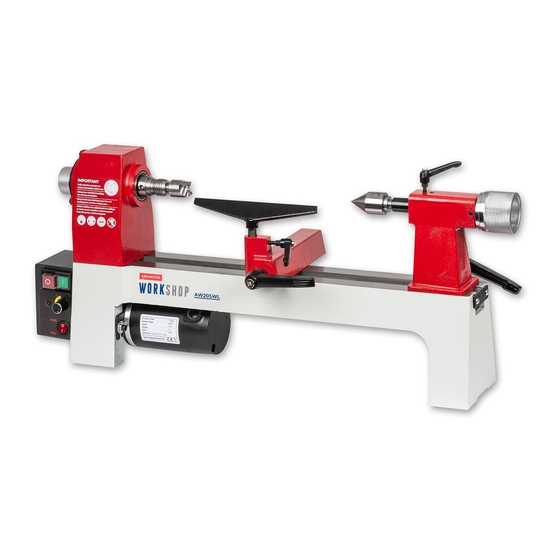
ASSEMBLY Fig 04 Mounting the Faceplate If you are intending to use the 80mm faceplate (B) you will need to remove the four prong drive centre (F) from the headstock. Locate the push rod (H), insert it through the headstock spindle to remove the drive centre, see fig 04. - Page 7 ILLUSTRATION AND PARTS DESCRIPTION Tailstock adjusting knob Headstock Tailstock barrel lock Headstock Live revolving centre Spindle adjusting knob 4 Prong drive centre Tool rest Banjo arm locking handle Motor Faceplate Fuse Tailstock Tool rest locking handle Tailstock Banjo locking handle Lathe bed Motor connector Power connector...
-
Page 8: Setup Procedures
LATHE FOOTPRINT Distance between centres 330mm Banjo & tool rest travel 400mm 730mm SET-UP PROCEDURES Centres Operating Height Postion the lathe on the work bench, make sure the surface is level and free of clutter. Tip. The correct operating height is ‘Elbow Height to Centres’, Stand in front of the lathe and check that your elbow is level with the drive and live centres, see diagram. - Page 9 OPERATING INSTRUCTIONS Fig 09-10 CLEAR ALL TOOLS AWAY FROM WORK AREA AND CONNECT TO THE MAINS SUPPLY! 1. Make sure the speed control dial is turned right down and press the power switch, see fig 8. Fig 08 2. Press the ‘GREEN’ button, the ‘LED’ indicator comes on and the lathe starts, see fig 09.
-
Page 10: Maintenance
OPERATING INSTRUCTIONS Removing Tailstock Assembly Fig 13 Fig 14 The tailstock can be removed to give you extra movement when turning. Remove the tailstock stop from the end of the lathe bed and place safely aside. Release the locking handle and slide the asssembly off the lathe bed, see fig 13-14. - Page 11 MAINTENANCE Monthly DISCONNECT THE LATHE FROM THE MAINS SUPPLY BEFORE CONTINUING! 1. Check the tension of the belt and adjust. If you find Loosen the hex bolt holding the motor plate, press the spindle is slipping or has stopped rotating check the down the motor assembly and re-tighten the bolt, see drive belt is under tension.
- Page 12 MAINTENANCE NOTE: Take careful note of the 3. If they are in good condition with Motor Brushes orientation of the brushes, plenty of carbon left on the brush, remember that they have bedded re-fit. If they are worn down to the themselves to the profile of the half way mark (7.5mm) we advise DISCONNECT THE...
- Page 13 EXPLODED DIAGRAMS/LISTS...
- Page 14 EXPLODED DIAGRAMS/LISTS Part Description Headstock Speed dial switch Headstock spindle nut Retaining plate Plate cover Bolt M5x8 Bolt M4x8 Bolt M6x8 Washer Handwheel Bolt M6x8 Tailstock Drive pulley Spindle lock handle Belt Bolt M8x50 Bolt M6x10 Sleeve Motor pulley Eccentric axis Power cord Tailstock quill Switch box assembly...
-
Page 15: Wiring Diagram
EXPLODED DIAGRAMS/LISTS Eccentric rod Washer Bolt M4x10 7” Tool rest Spanner 4.5” Tool rest Knock-out tool Bolt Ball knob Plate Hex wrench 3 Lock handle Hex wrench 5 Lock handle Plate cover Fuse Handwheel Carbon brush Spanner Screw M5X8 Spanner Set screw M6X12 Plate For and Rev Switch... - Page 16 The packaging is suitable for recycling. Please dispose of it in a responsible manner. EU Countries Only Do not dispose of electric tools together with household waste material. By law they must be collected and recycled separately. Axminster Tools, Axminster Devon EX13 5PH axminstertools.com...