Table of Contents
Advertisement
Quick Links
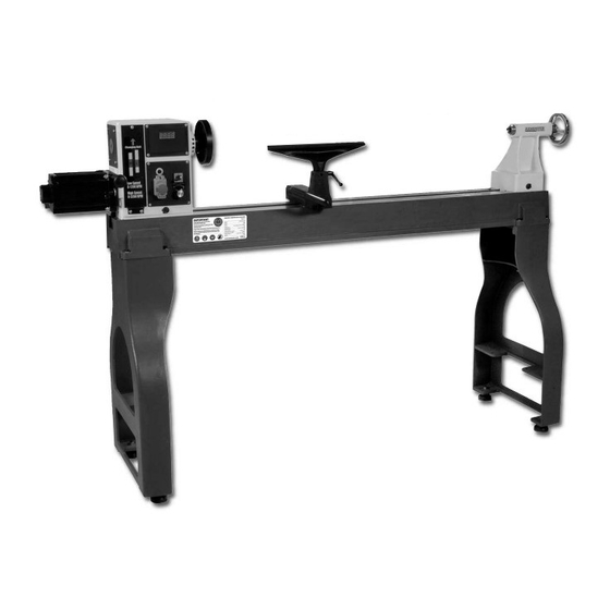
AWVSWL1200D
Woodturning Lathe
Code: 502517
This is a very capable machine aimed at the more experienced woodturner, offering
a high capacity of 1200mm(47") between centres and 450mm(18") diameter over
the bed. The motor is an inverter controlled, DC permanent magnet unit of 1.5kW
(2hp), combined with the 2 speed belt drive gives very high torque at the low
speeds plus a high speed of 3200rpm for smaller work, or finishing. All the controls
are grouped together on the front face of the headstock for convenience, along
with a digital read-out of the spindle speed. The spindle direction is easily reversed
with a simple toggle switch. Other features include the positioning of the headstock
anywhere along the bed, a spindle indexing facility at 10 degree intervals, camlock
action toolrest banjo and tailstock and a lock-off NVR switch. Supplied with
150mm(6") faceplate, Axminster 2MT drive centre, Axminster 2MT live tailstock
centre, indexing pins, 350mm(14") tool
Axminster Tool Centre,
Unit 10 Weycroft Avenue, Axminster, Devon EX13 5PH
www.axminster.co.uk
rest and centre
knock-out bar.
Advertisement
Table of Contents

Related Manuals for Axminster AWVSWL1200D


Summary of Contents for Axminster AWVSWL1200D
- Page 1 10 degree intervals, camlock action toolrest banjo and tailstock and a lock-off NVR switch. Supplied with 150mm(6") faceplate, Axminster 2MT drive centre, Axminster 2MT live tailstock centre, indexing pins, 350mm(14") tool rest and centre knock-out bar.
- Page 2 WOODLATHE MANUAL This manual contains information that is important for you to know and understand. This information relates to protecting YOUR SAFETY and PREVENTING EQUIPMENT PROBLEMS. To help you recognize this information, we use the symbols to the right. Please read the manual and pay attention to these sections. 1.
- Page 3 WOODLATHE MANUAL 12. USE THE RIGHT MACHINE. Don’t force a machine or an attachment to do a job for which it was not designed. Damage to the machine and/or injury may result. 13. USE RECOMMENDED ACCESSORIES. The use of accessories and attachments not recommended by Delta may cause damage to the machine or injury to the user.
- Page 4 WOODLATHE MANUAL according to the instructions. 2. OBTAIN ADVICE from your supervisor, instructor, or another qualified person if you are not familiar with the operation of this machine. 3. FOLLOW ALL WIRING CODES and recommended electrical connections. 4. ROUGH CUT THE WORKPIECE as close as possible to the finished shape before installing it on the faceplate.
- Page 5 WOODLATHE MANUAL THE “OFF” POSITION to prevent unauthorized use. 24. ADDITIONAL INFORMATION regarding the safe and proper operation of power tools. All grounded, cord-connected machines: In the event of a malfunction or breakdown, grounding provides a path of least resistance for electric current to reduce the risk of electric shock.
- Page 6 WOODLATHE MANUAL Contents of the Shipping Containers 1. Lathe 1. Tailstock 1. Headstock 1. Tool Rest Body 1. Owner’s Manual & Warranty Card Fig.1 Accessory Package Box 1. Live Center 1. Spur Center 1. Index Pin 1. Face Plate 1. Knockout Rod Headstock 1.
- Page 7 WOODLATHE MANUAL Secure tool rest (A, Fig. 3) to tool rest body (B, Fig. 3) by tightening handle(C, Fig. 3). Fig. 3 Fig. 4 CONTROLS & FEATURES 1. Headstock Lock Handle: (D, Fig.4) Locks head in position. Unlock handle to position the head along lathe bed.
- Page 8 WOODLATHE MANUAL clockwise direction, and tighten two set screws. Remove the faceplate by loosening two set screws. Push in headstock spindle lock and use the provided rod in faceplate holes to unthread the faceplate. 8. Headstock Indexing Hole: (L, Fig. 6) Thread indexing pin into the indexing hole making sure that it locates in the spindle hole.
-
Page 9: Lathe Tools
WOODLATHE MANUAL speed, where as the “Low” speed range (100-1200) will provide maximum torque. 4. Lower the tensioning handle so that the weight of the motor provides the needed tension and tighten the locking handle. Fig.9 Fig.10 OPERATION The following directions will give the inexperienced operator a beginning point for common lathe operations. -
Page 10: Centering The Work
WOODLATHE MANUAL The cutting technique, by virtue of faster wood removal and a cleaner surface, is the preferred method. CENTERING THE WORK Wood stock for any spindle turning should be approximately square, and the ends should be square with the sides. Two common methods of determining the center are shown in Figs. -
Page 11: Roughing A Cylinder
WOODLATHE MANUAL TOOL REST POSITION Mount the tool rest in place about 1/8” away from the work and 1/8” above the work centerline (Fig. 16.) This position may be varied to suit the work and the operator. Place a guide mark on the tool rest shank as an aid to quick and accurate resetting. Fig.17 Fig.18 ROUGHING A CYLINDER... -
Page 12: Position Of Hands
WOODLATHE MANUAL Fig.19 Fig.20 POSITION OF HANDS While turning, the hand that holds the tool handle should be in a natural position. This hand provides the leverage for the too l by either moving in toward the chisel or moving out. The position of the tool rest hand is more a matter of individual preference, rather than a “set”... - Page 13 WOODLATHE MANUAL...
- Page 14 WOODLATHE MANUAL Problem Possible Cause Solution 1. Work piece warped, out of Correct problem round, has major flaw, or planing, bandsawing, or was improperly prepared for scrap workpiece turning together Excessive Vibration. 2. Worn spindle bearings 2. Replace bearings 3. Worn belt 3.
- Page 15 WOODLATHE MANUAL Stand and Bed Assembly...
- Page 16 WOODLATHE MANUAL Headstock Assembly...
- Page 17 WOODLATHE MANUAL Parts List for the MC1200F Woodworking Lathe Q’TY Q’TY DESCRIPTION DESCRIPTION STAND WASHER SCREW M4x8 SCREW M5x12 CORD BRACKET SPRING WASHER 5 C-RING C-19 BAFFLE LEVER SPRING WASHER 10 POWER CORD CAP SCREW M10x35 STRAIN RELIEF C-RING C-19 MOTOR SET SCREW M5x10 KNOCKOUT ROD...
Need help?
Do you have a question about the AWVSWL1200D and is the answer not in the manual?
Questions and answers