Table of Contents
Advertisement
Quick Links
AT1416VS
Woodturning Lathe
The AW1416VS utilises the very reliable inverter
technology usually found on much larger machines
Electronic variable speed is a desirable feature for woodturners, enabling fine
tuning of speed to suit larger diameters or out of balance work pieces.
Axminster Tool Centre,
Unit 10 Weycroft Avenue, Axminster, Devon EX13 5PH
www.axminster.co.uk
Code: 501214
Advertisement
Table of Contents

Related Manuals for Axminster AT1416VS


Summary of Contents for Axminster AT1416VS
- Page 1 Electronic variable speed is a desirable feature for woodturners, enabling fine tuning of speed to suit larger diameters or out of balance work pieces. Axminster Tool Centre, Unit 10 Weycroft Avenue, Axminster, Devon EX13 5PH www.axminster.co.uk...
-
Page 2: Declaration Of Conformity
Index of Contents Index of Contents Declaration of Conformity What’s in the Box Optional Accessories General Instructions for 230V Machines 04-05 Specific Safety Instructions for Woodturning Lathes Specifications Assembly Instructions 06-07 Illustration and Description 08-09 Indexing Operation Removing Drive/Live Centres Changing the Belt Speed Maintenance Parts Breakdown... -
Page 3: What's Included
24 Index Pin with Magnetic Base 2 No Steel Hooks & (4) Phillips Screws 1 No Instruction Manual 1 No Guarantee Card Having unpacked your new AT1416VS woodturning lathe please dispose of the unwanted packaging responsibly. The cardboard packaging is biodegradable... -
Page 4: Optional Accessories
Optional Accessories Quantity Item 1 No Extension Bed (Product code: 951249) 2 No ” x 1” Caphead Bolts & Spring/washer General Instructions for 230V Machines that you have unimpeded access to all parts of the Good Working Practices/Safety machine. The machine is designed for indoor use, do not use when or where it is liable to get wet. -
Page 5: Specific Safety Instructions For Woodturning Lathes
7. If your lathe has the facility to run in reverse, you Specification Product Code 501214 Model AT1416VS Rating Trade Power 230V 50Hz 560W Speed 0-800, 200-1,750, 400-3,600rpm... -
Page 6: Assembly Instructions
Assembly Instructions Please take some time to read the section entitled Figure 02 “Illustration & Parts Description” to identify the various parts of your machine so that you are familiar with the terminology we will use to enable you to set up and operate your table lathe safely and correctly. - Page 7 (H) & lightly screw them into the lathe bed, using a Hex key. Clamp the tailstock over the two beds and adjust until both beds are aligned then tighten the bolts, (DO NOT OVERTIGHTEN). (See figures 7-8) Replace the carrying handle (E) and screws to the end of the extension bed (H). AT1416VS Lathe Extension Bed...
-
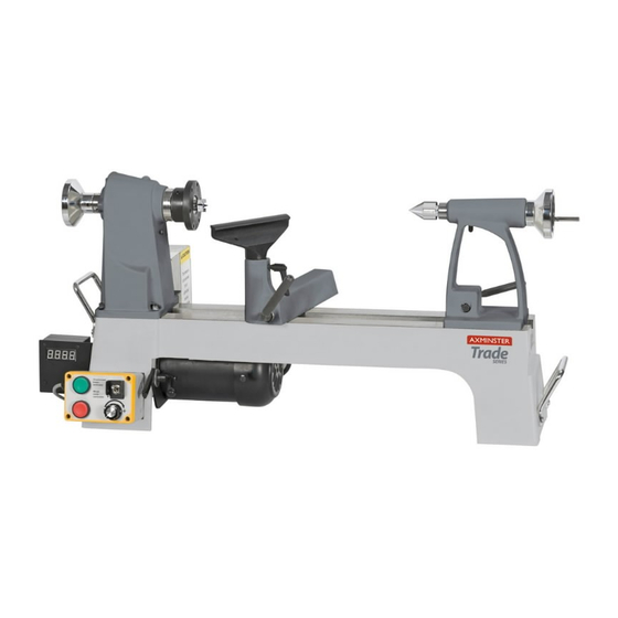
Page 8: Illustration And Description
Illustration and Description Tailstock barrel lock Access panel Access panel lock Drive centre Live centre Tailstock lock Power cable hooks Lathe bed Motor Electronic inverter Headstock wheel control unit Headstock Faceplate Tailstock wheel Tool rest Tool rest lock Carrying handle Banjo lock Banjo Lift and shift clamping handle... - Page 9 Illustration and Description Electronic Inverter Control Unit General Purpose AC Micro Drive from “Delta parameter display and shows operation status of the Electronics” . The VFD-S drive is famous for its low AC drive. The keypad provides programming noise carrier frequency feature and easy to use interface between the user and the AC drive.
-
Page 10: Indexing Operation
Indexing Operation The indexing facility is useful for fluted columns, clock faces and accurate hole positioning. The indexing pulley has 24 positions (15°) indexing using the supplied index pin (F). Figure 09 Figure 10 1-24 index positions Open the access panel, turn the headstock wheel until the pre-drilled hole in the headstock lines up with one of the 24 pre-drilled hole positions on the index pulley. -
Page 11: Removing Drive/Live Centres
Removing Drive/Live Centres To remove the Drive Centre (A), locate the push rod (C), while holding the tool insert the push rod (C) through the centre hole of the headstock wheel and push the drive centre out. (See figs 15-16-17) Repeat the procedure for the Live Centre in the tailstock. - Page 12 Changing the Belt Speed Tighten the lift and shift handle to hold the motor Figure 21 plate in position. Replace the access panel (A) and tighten the caphead screw (B) and close the motor access door (C). Reconnect the machine to the mains supply. Give the lathe a little ‘burst’...
-
Page 13: Maintenance
Maintenance Daily after use Monthly •Clean wood shavings away from the lathe bed and •Check the tension of the belt and adjust, (See pages tool rest. 11 & 12 for Changing the Belt Speed). •Smear a light coat of wax (Protec Tool Wax Polish, •Check any build up of wood shaving on the motor Order no. -
Page 14: Parts Breakdown
Parts Breakdown... - Page 15 Parts Breakdown...
-
Page 16: Parts List
Parts List 1... - Page 17 Parts List 2...
- Page 18 Parts List 3...
- Page 19 AW1416VS Lathe Stand (Optional) AW1416VS Lathe Stand (Product Code: 951248) LEG BASE LEG SUPPORT LEG BAR HEX SCREW 1.4" - 1/2" WASHER 1/4" CAP SCREW 3/8"- 1" WASHER 3/8" WHEEL FOOT 3/8" 3/8" NYLON NUT 5/16" WASHER 5/16" HEX SCREW 5/16"- 65MM...
-
Page 20: Wiring Diagram
Wiring Diagram...
Need help?
Do you have a question about the AT1416VS and is the answer not in the manual?
Questions and answers