Table of Contents
Advertisement
Quick Links
Advertisement
Table of Contents

Related Manuals for Levenhuk MAGUS BIO 290T


Summary of Contents for Levenhuk MAGUS BIO 290T
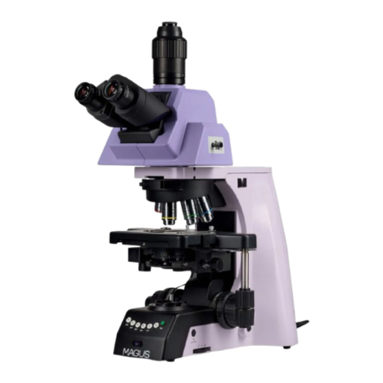
- Page 1 M AG US B IO 2 9 0T B I OLO G ICA L MIC RO S CO P E U S E R M A N U A L...
- Page 2 928 E 124th Ave. Ste D, Tampa, FL 33612, USA +1 813 468-3001 contact_us@levenhuk.com Levenhuk Optics s.r.o. (Europe) V Chotejně 700/7, 102 00 Prague 102, Czech Republic +420 737 004-919 sales-info@levenhuk.cz Magus® is a registered trademark of Levenhuk, Inc. © 2006–2024 Levenhuk, Inc. All rights reserved. www.levenhuk.com 20241113...
-
Page 3: Safety Precautions
Before using the microscope, please read this user manual carefully to study the instrument design, operation modes and procedures, operational limitations, and safety precautions. Due to the continuous improvements in the microscope design, this manual may not reflect minor design changes that do not affect the microscope performance and operation procedures. - Page 4 Do not use any other oily substance instead of proper immersion oil made specifically for the given purpose, as this will degrade the image quality and damage the lenses. Do not touch the lens surfaces with your fingers. Use a brush and special lens-cleaning solution to keep the lenses clean.
-
Page 5: Table Of Contents
CONTENTS 1 DESCRIPTION OF THE MICROSCOPE Purpose Specifications Microscope kit 2 COMPONENTS Stand Focusing mechanism Microscope head Eyepieces Objectives Condenser Stage Illuminator 3 UNPACKING AND ASSEMBLING 4 BRIGHTFIELD OBSERVATION PROCEDURE Switching on the illumination Placing the specimen Focusing on the specimen Motorized revolving nosepiece Adjusting the eyepiece tubes Setting up Köhler illumination... -
Page 6: Description Of The Microscope
MAGUS Bio 290T Biological Microscope has been designed and tested in accordance with the international safety standards. If properly used, the microscope is safe for the customer’s health, life, property, and the environment. Proper maintenance of the microscope is a prerequisite for its reliable and safe operation. -
Page 7: Microscope Kit
Phase-contrast turret condenser Phase-contrast technique* Centering telescope Set of phase-contrast objectives (10x, 20х, 40х, 100х) Oil darkfield condenser NA 1.3–1.26 Darkfield technique* Dry darkfield condenser NA 0.7–0.9 DIC turret condenser Set of semi-apochromatic objectives DIC technique* 10х/20х and 40х/100x DIC sliders Polarization filter Fluorescence technique* Fluorescence attachment, lamphouse, set of fluorescence objectives, UV shield... - Page 8 7 8 9 10 11 Fig. 1. MAGUS Bio 290T Biological Microscope. View from the right 7. Image capture button 12. XY stage control knob 1. Eyepieces 2. Eyepiece tubes 8. Field diaphragm ring 13. Stand 3. Revolving nosepiece 9. Coarse focusing tension 14.
- Page 9 Fig. 2. MAGUS Bio 290T Biological Microscope. View from the left 9. Coarse focusing lock knob 1. Binocular head with 4. Slot for optional accessories adjustable inclination 5. Stage 10. Coarse focusing knob 2. Interpupillary distance 6. Aperture diaphragm ring 11.
- Page 10 Fig. 3. MAGUS Bio 290T Biological Microscope. Rear view 1. Universal wrench holder 4. Connector for the transmitted light illuminator power cord 2. ON/OFF switch 5. Condenser locking screw 3. Connector for the microscope power cord...
-
Page 11: Components
COMPONENTS STAND The stand 13 (Fig. 1) is a one-piece structure with the base. The base has Y-shaped stable ergonomic design. Parts attached to the microscope stand: – revolving nosepiece 3 (Fig. 1) with objectives 4 (Fig. 1) – collector with a field diaphragm. Inside the stand is the focusing mechanism and the power supply of the transmitted light illuminator. -
Page 12: Microscope Head
M ICROS COPE H EA D The microscope head 16 (Fig. 1) is trinocular (binocular with a trinocular tube). The head provides the visual observation of the specimen image. The microscope head is installed in the mounting hole on the top of the microscope stand 3 (Fig. 1) and secured with a clamping screw 14 (Fig. 1). When installing the microscope head, turn the eyepieces towards the stage. -
Page 13: Condenser
Table 2: Numerical Working Coverslip, Color Objective identification System Magnification aperture distance, mm marking Plan 2х/0.06 ∞/– 2х 0.06 Plan 4х/0.10 ∞/– 4х 0.10 Plan 10х/0.25 ∞/– 10х 0.25 10.2 yellow Plan 20х/0.40 ∞/0.17 20х 0.17 green Plan 40х/0.65 ∞/0.17 40х... -
Page 14: Illuminator
I L LUM INATO R The transmitted light illumination system is made up of a collector with a field diaphragm, built-in filter, and a lamphouse with a LED light source. The beam is directed to the collector by a built-in system of lenses and mirrors. The illuminator is switched on by means of an ON/OFF switch 2 (Fig. - Page 15 Fig. 5 (a, b). Installing the stage and condenser holder 5. Insert the stage, aligning with the center of the round holder. Tighten the screw 1 until the stage is fixed. Fig. 6 (a, b). Installing the stage 6. Insert the microscope head into the mounting hole of the stand and tighten the screw.
- Page 16 8. Install the condenser as far as it will go and secure it with the screw located on the right. Plug the power cable of the flip-down lens mechanism into the connector in the stand base (to the left of the collector). Fig.
-
Page 17: Brightfield Observation Procedure
BRIGHTFIELD OBSERVATION PROCEDURE SWITCHING ON T H E I LLU MI N ATI O N Before switching on the ON/OFF switch, make sure that the input voltage of the microscope power supply matches the local mains voltage. If not, do not switch on the microscope. Improper input voltage may result in a short circuit or fire. Make sure that the power cord is plugged into the connector on the back panel of the microscope stand. -
Page 18: Focusing On The Specimen
You can adjust the tension of the stage control knobs. Pull down knob A and you will see two adjustment rings (B, C). В – adjustment ring for the Y-axis movement knob. C – adjustment ring for the X-axis movement knob. Fig. -
Page 19: Motorized Revolving Nosepiece
M OTOR IZE D REVO LV IN G N O S EP I EC E The front panel of the microscope has objective selection buttons 1. When you press a button, the revolving nosepiece automatically sets the selected objective to its operating position. On both sides of the microscope, next to the focusing knobs, there are buttons for rotating the nosepiece 3. -
Page 20: Setting Up Köhler Illumination
SE TTI N G U P KÖ H L ER IL LU MI NAT IO N In the light optical microscope, the image quality depends equally on the optics and on the illumination system, so adjusting the illumination is an important preparatory step. The illumination system affects the image resolution, comfort during long observation, and photo quality when using digital cameras. -
Page 21: Using Oil Immersion Objectives
The size of the aperture diaphragm affects the image contrast. Do not increase the image brightness by opening the aperture diaphragm, as this will result in loss of contrast and low resolution. The brightness is only adjustable with the brightness adjustment ring. The greater the magnification of the objective, the larger is its aperture, and the larger is the opening of the condenser diaphragm. -
Page 22: Phase-Contrast Device
We recommend setting up the darkfield illumination with the oil condenser as follows: – Raise the stage all the way up using the coarse focusing knob. Lower the condenser all the way down using the condenser focus knob. Loosen the screw of the brightfield condenser holder while leaving the centering screws untouched. -
Page 23: Eyepiece With A Scale
USI N G THE E YEP IECE WIT H A SCAL E The eyepiece with a scale or reticle can be used to make comparative analysis of the linear dimensions of the individual components of an object. The scale is installed in the plane of the field diaphragm of the 10x eyepiece. The eyepiece with a scale is installed in the tube in place of the eyepiece of your microscope. -
Page 24: Camera
CAM ERA The microscope is designed to observe a specimen through the eyepieces and to photograph the specimen. The vertical camera port (trinocular tube) is located on the top of the microscope head. There is a C-mount adapter 1 mounted in the trinocular tube to use the camera. -
Page 25: Troubleshooting
6 TROUBLESHOOTING Potential problems and remedies (Table 3): Problem Cause Remedy ELECT RI CAL C OMPONENTS The ON/OFF switch is off Turn the ON/OFF switch to ON The bulb is burned out Replace the bulb. Contact an electronics No illumination in the field technician at the service center of view The circuit board connector has poor... -
Page 26: Scope Of Delivery
MECH ANI CAL C OMP ONENTS The image does not remain The coarse focusing tension adjusting Adjust the coarse focusing tension sharp during observation knob is loosened, causing the stage adjusting knob to lower spontaneously The coarse focusing knob is too The coarse tension adjusting knob Loosen the tension of the coarse focusing tight to rotate... - Page 27 20x/12mm eyepiece Optional 30x/8mm eyepiece Optional Dry darkfield condenser Optional Oil darkfield condenser Optional DIC device Optional Phase-contrast device: phase-contrast condenser, centering telescope, set of Optional phase-contrast objectives Polarizer/analyzer set Optional Reflected light illuminator for the brightfield and polarized light microscopy, with Optional a lamphouse and a power cable Epi-fluorescence illuminator with a LED light source, a fluorescence filter assembly,...
-
Page 28: Care And Maintenance
CARE AND MAINTENANCE R EPL ACING THE B ULB A N D FU SE If the fuse has burned out, replace it with a fuse with the same specifications. Before replacing the power adapter, turn the ON/OFF switch to "0" position (off). Unplug the power cord from the power outlet. -
Page 29: Magus Warranty
MAGUS provides a 5-year international warranty from date of purchase (valid for the entire life of the instrument). The Levenhuk company warrants the product to be free from defects in materials and workmanship. The Seller warrants that the MAGUS product you have purchased meets specification requirements, provided that the Buyer complies with terms and conditions of transport, storage, and operation of the product. - Page 30 www.magusmicro.com...
Need help?
Do you have a question about the MAGUS BIO 290T and is the answer not in the manual?
Questions and answers