Advertisement
Quick Links
Advertisement

Related Manuals for Levenhuk MAGUS BIO 240B


Summary of Contents for Levenhuk MAGUS BIO 240B
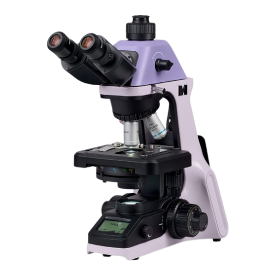
- Page 1 M AG U S B I O 24 0B | 24 0T | D H 24 0 B IO LOG ICA L MI CRO S C OP E U S E R M A N U A L...
- Page 2 Before using the microscope, please read this user manual carefully to study the instrument design, operation modes and procedures, operational limitations, and safety precautions. Due to the continuous improvements in the microscope design, this manual may not reflect minor design changes that do not affect the microscope performance and operation procedures.
- Page 3 11. Do not use any other oily substance instead of proper immersion oil made specifically for the given purpose, as this will degrade the image quality and damage the lenses. 12. Do not touch the lens surfaces with your fingers. Use a brush and special lens-cleaning solution to keep the lenses clean.
- Page 4 CONTENTS 1 DESCRIPTION OF THE MICROSCOPE Purpose Specifications Microscope kit 2 COMPONENTS Stand Focusing mechanism Microscope head Eyepieces Revolving nosepiece Objectives Condenser Stage Illuminator Built-in digital camera (DH240) 3 UNPACKING AND ASSEMBLING 4 OPERATION Switching on the illumination Adjusting the LCD screen functions Placing the specimen Focusing on the specimen Adjusting the eyepiece tubes...
- Page 5 MAGUS Bio 240 Biological Microscope has been designed and tested in accordance with the international safety standards. If properly used, the microscope is safe for the customer’s health, life, property, and the environment. Proper maintenance of the microscope is a prerequisite for its reliable and safe operation. DESCRIPTION OF THE MICROSCOPE P UR POSE The microscope is designed for observing objects in transmitted light using the brightfield technique.
- Page 6 Automatic brightness adjustment during objective change, color temperature Intelligent lighting control system adjustment, LCD status screen, standby mode, eco mode Color filter green LCD screen Camera – – Wi-Fi – – C-mount camera adapter – 0.5х – AC/DC power adapter is external and mounted in a special socket on the back of the stand Power supply AC input voltage 100V–240V, 50/60Hz...
- Page 7 M ICROS COPE K IT The microscope kit includes the following main components: – stand with the transmitted light source, focusing mechanism, stage, condenser, and revolving nosepiece – power adapter – microscope head – set of objectives and eyepieces – set of spare parts and accessories –...
- Page 8 Fig. 1. MAGUS Bio 240 Biological Microscope. View from the right 1. Eyepieces 6. Lighting control knob 10. X/Y stage control knob 2. Eyepiece tubes 7. Coarse focusing tension 11. Head locking screw adjusting knob 3. Revolving nosepiece 12. Trinocular tube (MAGUS Bio 240T) 8.
- Page 9 Fig. 2. MAGUS Bio 240 Biological Microscope. View from the left 1. Stage 5. LCD screen 9. Fine focusing knob 10. Stand 2. Aperture diaphragm control 6. ON/OFF switch 3. Abbe condenser 7. Coarse focusing lock knob 11. Microscope head 4.
- Page 10 Fig. 3. MAGUS Bio 240 Biological Microscope. Rear view 1. Abbe condenser locking screw 4. Power connector 6. Microscope head with built-in camera (DH240) 2. Anti-theft lock hole 5. Convenient handle for carrying the microscope with two hands 7. Interpupillary distance 3.
- Page 11 COMPONENTS STAND The stand 10 (Fig.2) is a one-piece structure with the base. The base has Y-shaped stable ergonomic design. Parts attached to the microscope stand: – revolving nosepiece 3 (Fig. 1) with objectives 4 (Fig. 1) – stage 1 (Fig. 2) –...
- Page 12 The interpupillary distance is adjusted by rotating the eyepiece tubes 2 (Fig. 1) in the range of 47–75mm. The distance between the eyepieces matching the observer's interpupillary distance is marked on the adjustment scale 7 on the microscope head (Fig. 3). For convenience, the microscope head is inclined at 30°.
- Page 13 The specifications of the objectives are given in Table 2: Objective Numerical Working Coverslip, Color System Magnification identification aperture distance, mm marking PL 4х/0.10 ∞ /– 4х 0.10 – PL 10х/0,25 ∞/0,17 10х 0.25 0.17 yellow PL 20х/0,40 ∞/0,17 20х 0.40 0.17 green...
- Page 14 BUI LT-I N D I GITAL CAME RA ( D H 24 0 ) 1. LAN port 2. USB port (for mouse/keyboard) 3. Mini-USB port 4. HDMI port 5. USB port (for mouse/keyboard) Fig. 4. General view of the microscope head with a built-in camera HDMI mode Use an HDMI cable to connect the digital microscope head to an HDMI monitor (4).
- Page 15 3 UNPACKING AND ASSEMBLING The assembly procedure is given in Fig. 5. Fig. 5. Assembling the microscope 1. Remove the microscope from the package. 2. Check the scope of delivery using Section 7 of the User Manual. 3. Inspect the microscope and its components for damage. 4.
- Page 16 6. Raise the stage all the way up. Place the Abbe condenser in the correct position with the aperture diaphragm control facing forward. Secure the condenser with two screws. 7. Turn button 1 to the OFF position before plugging the power cord. 8.
- Page 17 4 OPERATION SWITCHING ON T H E I LLU MI N ATI O N Before switching on the ON/OFF switch, make sure that the input voltage of the microscope power supply matches the local mains voltage. If not, do not switch on the microscope. Improper input voltage may result in a short circuit or fire.
- Page 18 5. Sleep mode. Press the knob once briefly to activate the standby mode. The screen will display "SLEEP" as shown in Fig. 15. Press the knob once again to leave the Sleep mode: The "SLEEP" message will disappear, and you will return to the normal operation mode. 6.
- Page 19 PL AC IN G THE SP EC IM E N Place the specimen 1 on the stage. Adjust the image by moving the stage control knobs 2 and 3 so that the observed section of the specimen is directly under the objective. The stage attachment features an XY control system.
- Page 20 ADJ U STI N G THE E YE P I ECE T UB ES Use a diopter adjustment on the eyepiece tubes to compensate for the observer's ametropia. The adjustment range is ± 5 diopters. First set the diopter adjustment 1 on both tubes to the middle position. While looking through the eyepiece installed in one tube (with the other eye closed), bring the specimen into focus.
- Page 21 Fig. 17. Adjusting the aperture diaphragm Adjusting the aperture diaphragm. The aperture iris diaphragm is designed to adjust the numerical aperture, not brightness. Setting the aperture iris diaphragm to 70–80% of the numerical aperture of the objective used ensures a good contrast image.
- Page 22 USING OPTIONAL EQUIPMENT U SING THE EYEP I ECE W I TH A SCALE The eyepiece with a scale or grid can be used to make comparative analysis of the linear dimensions of the individual components of an object. The scale is installed in the plane of the field diaphragm of the 10x eyepiece. The eyepiece with a scale is installed in the tube in place of the eyepiece of your microscope.
- Page 23 USI N G THE CA ME RA ( MAGUS B IO 2 4 0T ) The microscope is designed to observe a specimen through the eyepieces and to photograph the specimen. The vertical camera port (trinocular tube) is located on the top of the microscope head. There is a C-mount adapter 1 mounted in the trinocular tube to use the camera.
- Page 24 TROUBLESHOOTING Potential problems and remedies are given in Table 3: Problem Cause Remedy ELECT RI CAL C OMPONENTS The ON/OFF switch is off Turn the ON/OFF switch to ON The bulb is burned out Contact the service center to have the bulb replaced by an electronics technician No illumination in the field of view...
- Page 25 MECHANI CAL C OMPONENTS The image does not remain The coarse focusing tension adjusting Adjust the coarse focusing tension sharp during observation knob is loosened, causing the stage adjusting knob to lower spontaneously The coarse focusing knob is too The coarse tension adjusting knob is Loosen the tension of the coarse tight to rotate overtightened...
- Page 26 ACCESSORIES AND SPARE PARTS Head locking screw Allen wrench Trinocular tube dust cap Supplied Light source - 3W LED Transmitted light filter Power adapter Power cord Bottle of immersion oil Dust cover User manual CARE AND MAINTENANCE R EPL AC ING THE B U LB AN D P OWE R ADA PT ER If the power adapter has burned out, replace it with an adapter with the same specifications.
- Page 27 MAGUS provides a 5-year international warranty from date of purchase (valid for the entire life of the instrument). The Levenhuk company warrants the product to be free from defects in materials and workmanship. The Seller warrants that the MAGUS product you have purchased meets specification requirements, provided that the Buyer complies with terms and conditions of transport, storage, and operation of the product.
- Page 28 www.magusmicro.com...
Need help?
Do you have a question about the MAGUS BIO 240B and is the answer not in the manual?
Questions and answers