Table of Contents
Advertisement
Quick Links
Advertisement
Table of Contents

Related Manuals for Vacon OPTE6


Summary of Contents for Vacon OPTE6
- Page 1 ® vacon ac drives canopen option board opte6 user manual...
-
Page 3: Table Of Contents
Release date: 28102024 Safety ........................6 Danger............................6 Warnings ........................... 7 Earthing and earth fault protection ..................8 CANopen option board OPTE6 - General ..............9 Overview ............................ 9 Software ............................ 9 2.2.1 CAN............................9 2.2.2 CANopen............................ 9 CANopen protocol description ................10 NMT ............................ -
Page 4: Vacon
6.3.2 OPTE6 option board firmware update with VACON® Loader ..........43 6.3.3 PC Tools for VACON® NXP: NCDrive ..................46 6.3.4 PC Tools for VACON® 100 and VACON® 20: VACON Live ............. 48 Quick instructions for controlling the motor................51 CANopen option board interface ................ - Page 5 • 5 13.1 Requirements for communication modes................90 13.2 Fiedlbus communication mode features and limitations ............91 13.3 Normal fieldbus communication .................... 92 13.4 Fast fieldbus communication ....................93 13.5 Normal Extended Mode ......................94 Appendix F - Parameters for application developers .......... 95...
-
Page 6: Safety
• 6 Safety AFETY This manual contains clearly marked cautions and warnings that are intended for your personal safety and to avoid any unintentional damage to the product or connected appliances. Please read the information included in cautions and warnings carefully. -
Page 7: Warnings
Safety vacon • 7 Warnings The AC drive is meant for fixed installations only. 13006.emf Do not perform any measurements when the AC drive is connected to the mains. 13006.emf The earth leakage current of the AC drives exceeds 3.5mA AC. According to standard EN61800-5-1, a reinforced protective ground connection must be ensured. -
Page 8: Earthing And Earth Fault Protection
• 8 Safety Earthing and earth fault protection CAUTION! 13006.emf The AC drive must always be earthed with an earthing conductor connected to the earthing terminal marked with The earth leakage current of the drive exceeds 3.5 mA AC. According to EN61800-5-1, one or more... -
Page 9: Canopen Option Board Opte6 - General
OPTE6 - G OPEN OPTION BOARD ENERAL ® ® The VACON OPTE6 CANopen option board can be used with the following VACON AC drives. ® Table 1. OPTE6 usage in different VACON AC drives From AC drive SW From OPTE6... -
Page 10: Canopen Protocol Description
• 10 CANopen protocol description OPEN PROTOCOL DESCRIPTION NMT network management manages CANopen, and is a mandatory, common feature for all devices. The protocol describes several node control services and the state machine. Power on or hardware reset Initialisation... -
Page 11: Node Control Protocols
CANopen protocol description vacon • 11 Node control protocols Protocol start remote node The start remote node message sets the node(s) into operational state. See Figure 1. NMT state machine. If the node ID in the message is set to ‘0’, the message affects all nodes (broadcast). -
Page 12: Error Control Protocols
• 12 CANopen protocol description Protocol reset communication The reset communication message makes the node(s) apply communication reset. See Figure 1. NMT state machine. Communication reset does not affect the object dictionary values. If the node ID in the message is set to ‘0’, the message affects all nodes (broadcast). After the node has made the communication reset, it will enter the pre-operational state automatically from the initializing state. -
Page 13: Node Guarding Protocol
RTR frames in CAN controllers. OPTE6 option board does not have a hardware-triggered automatic response to the RTR frame. RTR information is handled by software, and the response data always consists of updated information. - Page 14 • 14 CANopen protocol description Table 15: EMCY message CAN ID LENGTH DATA0 DATA1 DATA2 DATA3 DATA4 DATA5 DATA6 DATA7 0x80 + MSEF Node ID Table 16: EMCY message data fields Emergency error code Error register value MSEF Manufacturer-specific error code...
-
Page 15: Sdo Protocol
CANopen protocol description vacon • 15 All communication errors are reset if a reset command is given. This does not however reset drive faults if there are active error sources. EMCYs are also created in some cases, even though a fault is not created. These are for notification only. - Page 16 • 16 CANopen protocol description Some objects have limitations for SDO usage at the operational state. The following SDO abort codes can be returned by the OPTE6 option board. Table 22: SDO abort codes Abort code Description 0504 0001h Client/server command specifier not valid or unknown...
-
Page 17: Pdo Protocol
There are two different types of PDOs. Transmit PDOs for producing data into network and Receive PDOs for consuming data from network. OPTE6 board supports 5 receive and 5 transmit PDOs. Each of rxPDO and txPDO mapping parameter record contains four (4) process data items. For example, 0x01600 Receive PDO Mapping Parameter 1 contains following process data items: •... -
Page 18: Pdo Communication Parameter Record
• 18 CANopen protocol description 3.5.1 PDO communication parameter record PDO communication parameter record defines the COB-id, transmission type and how often the PDO is transmitted. The fields can be modified during the pre-operational state. Table 24: PDO communication parameter record... -
Page 19: Transmission Type
Event-driven means that the PDO can be transmitted at any time based on the occurrence of the internal event of the CANopen device. An event that triggers the OPTE6 transmission occurs when the data mapped into the PDO is changed. Also, an event timer can be used to create transmit events. -
Page 20: Pdo Parameter Mapping Record
By default Event timer value is zero, which together with Event-driven transmission type means that OPTE6 CANopen transmits TPDO only when its data content changes. In certain situations TPDO data content rarely or never changes. For example, when running zero speed, TPDO1 data content (status word and actual speed) does not change after zero speed has been reached. -
Page 21: Sync Protocol
CANopen protocol description vacon • 21 To data map the PDOs, first disable the related PDO COB ID in the pre-operational state. In the mapping structure, write the sub-index 0 to zero (number of mapped objects). Then write the mapping structures on the mapping parameter record, starting from the sub-index 1. When you have written all the necessary structures, write the sub-index 0 to correspond to the mapped objects. - Page 22 • 22 CANopen protocol description (1) (2) (3) (4) (5) (6) (7) (8) SYNC time txPDO Figure 2. txPDO responses to SYNC messages Table 33: Sync-related object in OD Index Description 0x1005 COB ID SYNC 0x1019 Synchronous counter 0x1014...
-
Page 23: Communication Objects
CANopen protocol description vacon • 23 Communication objects 3.7.1 0X1000 - Device Type The device type object indicates basic information about the device, including the supported device profile and the profile settings. Table 34: 0x1000 Device type Index Sub-index Value... -
Page 24: 0X1003 - Pre-Defined Error Field
• 24 CANopen protocol description 3.7.3 0X1003 - Pre-defined Error Field Predefined error field is a list of errors signaled with an EMCY object, listing the error history of up to 9 error entries. Sub-index 1 contains the latest error. -
Page 25: 0X1014 - Cob Id Emcy
CANopen protocol description vacon • 25 3.7.7 0X1014 - COB ID EMCY The object defines the emergency message COB ID. Table 41: 0x1014 COB ID EMCY Index Sub-index Value Name Data type Access 0x00000080+ 0x1014 COB ID EMCY UNSIGNED32 node id Setting MSB (bit 31) to 1 will disable sending of EMCY messages. -
Page 26: 0X1018 - Identify Object
• 26 CANopen protocol description Table 45: Heartbeat message CAN ID LENGTH DATA0 0x700 + node Node state 3.7.10 0X1018 - Identify Object The object gives information about the option board Table 46: 0x1018 Identify object Index Sub-index Value... -
Page 27: Saving And Restoring The Object Dictionary
CANopen protocol description vacon • 27 Saving and restoring the object dictionary CANopen defines a way of restoring the values in an object dictionary to the defaults and saving the values if the modified values must be valid after the power cycle. The manufacturer-specific bypass configuration can be restored to the object dictionary. -
Page 28: Canopen Option Board Opte6 - Technical Data
• 28 CANopen option board OPTE6 - technical OPTE6 - OPEN OPTION BOARD TECHNICAL DATA General Table 52. Technical data of CANopen option board CAN bus electrical 500 V DC isolation Ambient Same as for the used AC drive. Refer to the drive manual. -
Page 29: New Features
CANopen option board OPTE6 - technical data vacon • 29 New features The following table shows new major features that are added in the OPTE6 CANOpen option board's firmware versions. Table 53. OPTE6 CANopen firmware versions Firmware New features version ®... -
Page 30: Isolated Ground Connection
4.3.1 Isolated ground connection The OPTE6 option board is galvanically isolated. In CANopen networks that are completely galvanically isolated the CAN ground signal is carried in the cable line. It is connected at only one point into common ground potential. If one CAN device with not galvanically isolated interface is connected to the network, the potential for isolated CAN ground is given. -
Page 31: Recommended Cable
CANopen option board OPTE6 - technical data vacon • 31 4.3.2 Recommended cable For all OPTE6 installations the use of 4-wire cable is recommended. 4 wires enable the connection of isolated digital grounds with nodes. ® VACON recommends the following cable: ®... -
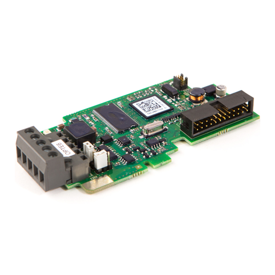
Page 32: Opte6 Layout And Connections
LAYOUT AND CONNECTIONS Layout and connections OPTE6 has two different hardware revisions with slightly different layout. Layout is different in LED arrangement and termination resistor orientation. The two hardware revisions are marked with different product codes, and this product code can be located from the sticker on the top side (location marked in Figure 6). -
Page 33: Led Indications
OPTE6 layout and connections vacon • 33 CAN connector pinout Pin out CAN GND, isolated digital ground reference CAN LO Shield connector CAN HI No connection LED Indications M A N N A M 70CVB01605 70CVB01124 9339A_00 Figure 8. LED indicators... -
Page 34: Jumper Settings
• 34 OPTE6 layout and connections Board status led (green) LED is Description Option board is not activated. Option board is in initialization state, waiting activation command from the AC drive. Option board is activated and in RUN state. Option board is ready for external Blinking (once/1s) communication. -
Page 35: Commissioning
• 35 OMMISSIONING This chapter describes how to commission the OPTE6 board for use. For instructions on how to set- up the AC drive to be controlled over fieldbus, refer to Chapter 10 Appendix B - Fieldbus parame- trization. -
Page 36: Opte6 Additional Panel Parameters
® From VACON 100 (INDUSTRIAL V027 and FLOW V018) and OPTE6 V009 firmware version forwards, CANopen bus communication parameters are stored and can also be modified directly from panel parameters. The stored parameters are modifiable and stored under the "Parameters" menu and these parameters are restored after power cycle. - Page 37 Commissioning vacon • 37 Table 60. OPTE6 board CANopen object parameters under General folder Parameter Default Reference COB-ID EMCY 0x80 + Node ID 3.7.7 Sync Counter Ovf. 3.7.11 Error Behavior 3.7.12 Sub menu: Heartbeat Producer Time 3.7.9 Consumer Time 1...
- Page 38 • 38 Commissioning Table 60. OPTE6 board CANopen object parameters under General folder Parameter Default Reference Number of Entries Application Obj. 0x20000410 Application Obj. 0x20000510 3.5.4 Application Obj. 0x20000610 Application Obj. 0x20000710 Sub menu: RPDO3 Mapping Number of Entries Application Obj.
-
Page 39: Panel Parameter Change Reaction
This chapter clarifies the changes that occur in OPTE6 while parameters are changed from panel parameters or from CANopen objects that are linked to these parameters. Note that there are some differences between OPTE6 versions. -
Page 40: Replacing Option Board And Parameter Restore
After the restore the parameter value is set back to zero automatically. 6.1.3 Replacing option board and parameter restore CANopen parameters must be defined for OPTE6 CANopen board in case the board is replaced in the field. Table 56 defines OPTE6 basic parameters and Table 60 defines CANopen communication parameters. - Page 41 100 FLOW (control firmware FW0159V018 or newer) From the following AC drive models it is possible to take parameter backup of the OPTE6 board's basic parameters that are defined in Table 56. The backup can be taken and restored from/to the ®...
-
Page 42: Opte6 Panel Monitor Values
® From VACON 100 (INDUSTRIAL V027 and FLOW V018) and OPTE6 V009 firmware version forwards, the active CANopen object values are visible as monitoring values. These values are the currently active settings and are equal to values read via CANopen objects. These objects might have different values than the stored parameters, depending if parameters written via bus are stored or not. -
Page 43: Vacon Pc-Tools
The VACON Loader can be downloaded from www.danfoss.com/en/service-and-support/ -> ® Downloads -> Software -> select "Drives" as Business unit. It is bundled with the VACON Live soft- ware package. After starting the installation program, follow the on-screen instructions. The OPTE6 CANopen firmware can be downloaded from www.danfoss.com/en/service-and-sup- port/ ->... - Page 44 • 44 Commissioning Step 1: Connect your PC to the controller by using the serial cable. Then select the firmware file which you want to load to the option board and double click it. This will ® start the VACON Loader software.
- Page 45 Commissioning vacon • 45 Step 3. Select the modules to be updated, press 'next' and wait until the operation is finished. Figure 11. Option board module selection ® Figure 12.VACON Loader: Loading is finished Local contacts: https://www.danfoss.com/en/contact-us/contacts-list/...
-
Page 46: Pc Tools For Vacon® Nxp: Ncdrive
NXP drive • In case of Serial connection: ® If PC contains RS232 serial port, then connect the serial cable from PC to VACON NXP con- trol unit's 9-pin DSUB connector (female). If PC does not contain RS232 serial port, then USB - RS232 converter device is needed between PC and NXP control. - Page 47 Figure 15. NCDrive: Loading information from the drive To change the option board settings, navigate to the "M 7 Expander boards" menu and select the slot in which OPTE6 CANopen is connected to. It is possible to change parameters defined in Chap- ter 6.1 OPTE6 panel parameters.
-
Page 48: Pc Tools For Vacon® 100 And Vacon® 20: Vacon Live
100 or VACON 20 AC drive • In case of Serial connection: VACON Serial Cable (USB - Serial cable) which is connected from PC to AC drive control unit. ® In case of VACON 20 also MCA (Micro Communications Adapter) is required. This adapter is ®... - Page 49 • 49 ® Figure 18. VACON Live: Communication settings Step 3: After successful scanning VACON Live shows the drive in connected drives window. Select ® the drive and press "Connected to Selected". After this VACON Live reads parameter and monitor value tree from the drive.
- Page 50 • 50 Commissioning 6.3.4.3 OPTE6 CANopen parameters in VACON® Live OPTE6 CANopen parameters and monitor values can be found from "5. I/O and Hardware" menu. ® With VACON Live it is possible to modify OPTE6 CANopen parameters and view monitor values.
-
Page 51: Quick Instructions For Controlling The Motor
RS485 and CAN Bus Option Boards Installation 1. Set the OPTE6 jumpers, refer to the Guide 2. Install OPTE6 option board in VACON® AC drive and connect the CAN cable, refer to the ® VACON RS485 and CAN Bus Option Boards Installation Guide 3. -
Page 52: Canopen Option Board Interface
• 52 CANopen option board interface OPEN OPTION BOARD INTERFACE By default, the CANopen option board is configured to operate in Drive Profile mode. The drive pro- file implementation is ‘Velocity Mode’ which is defined in CiA 402 specification with PDO set for the AC drive. -
Page 53: Velocity Mode
CANopen option board interface vacon • 53 Velocity mode The velocity mode is one of the specific modes that CIA-402 Drive Profile defines. Common behavior in all modes are PDS state machine, some control and status bits and certain objects. - Page 54 • 54 CANopen option board interface Bits of the controlword Command Transitions Bit 7 Bit 3 Bit 2 Bit 1 Bit 0 Shutdown 2.6.8 Switch on Switch on + enable 3 + 4 operation (NOTE) Disable voltage 7,9,10,12 Quick stop...
- Page 55 CANopen option board interface vacon • 55 The table below explains the actions taken in different state transitions and which event triggers which state transition. If the used drive/application does not support different stop bits in Fixed Control Word, the stop method will always be according to set stop function.
-
Page 56: Cia-402 Objects
• 56 CANopen option board interface 7.2.2 CiA-402 objects 7.2.2.1 0X6040 - Controlword Controlword is used to control the drive operation according to the PDS state machine. By default, Controlword is mapped into the first two bytes of rxPDO1. - Page 57 CANopen option board interface vacon • 57 7.2.2.3 0X6042 - vl Target Velocity The signed value of motor rpm speed request to drive. A negative value means that the motor is run- ning clockwise. By default, the object is mapped into the last two bytes of rxPDO1.
- Page 58 • 58 CANopen option board interface 7.2.2.7 0X6048 - vl Velocity Acceleration This object indicates the configured delta speed and delta time of the slope of the acceleration ramp. 0x6048.01: Delta speed Maximum change of rpm the motor will accelerate during the time specified in Delta Time.
-
Page 59: Pdo Configuration
CANopen option board interface vacon • 59 7.2.3 PDO configuration This chapter describes the default PDO mapping configuration when using CiA-402 velocity mode. By default, RPDO/TPDO 2 - 5 are disabled. These settings are restored when: • changing the operate mode to "Velocity" from either panel or object 0x6060 •... -
Page 60: Pdo Configuration
* Disabled by default Default process data application mapping This chapter describes the default mapping of the OPTE6 process data variables to the application data in the drive. It also provides a description of the application data in the drive. Supported con- trol/status word bits might differ depending on used application. -
Page 61: Fb Control Word
CANopen option board interface vacon • 61 7.4.1 FB Control Word Table 76. FB Control Word ESTP JOG2 JOG1 BREF BCTRL ZREF FRMP ZRMP STPM2 STPM1 FRST STRT Table 77. FB Control Word description Name Description ESTP Emergency Stop Request as fast stop as possible... -
Page 62: Fb Speed Reference
• 62 CANopen option board interface 7.4.3 FB Speed Reference Table 80. FB Speed Reference FB Speed Reference Table 81. FB Speed reference description Name Description FB Speed Reference Frequency reference at percentage between minimum and 10000 maximum frequency. Control word DIR bit is used to select (0%) (100.00%) -
Page 63: Fb Status Word Extension (General Status Word)
CANopen option board interface vacon • 63 7.4.7 FB Status Word Extension (general status word) Table 85. FB Status word extension Table 86. FB Status word extension description Name Description Control Place Drive Control place information 0,0,1-(1) Fieldbus 0,1,0- (2) Panel... -
Page 64: Vacon Anyparameter Service
CANopen option board interface VACON anyparameter service For access to AC drive parameters and monitoring values, the OPTE6 maps the CANopen manufac- turer segment 0x2100 - 0x5FFF into the application IDs of the drive based on the IEC61131 standard. Both read and write access is supported. -
Page 65: Examples
CANopen option board interface vacon • 65 7.5.2 Examples In the examples below, the following ID values are used: • 102 = Maximum frequency (Hz) • 600 = Motor control mode Table 91. Example 1: Reading values from different AC drives... -
Page 66: Fault Tracing
® ® • In case of VACON Live connect to the drive and select from VACON Live menu bar: Drive - > Service information… • In case of NCDrive connect to the drive and select from NCDrive menu bar: File -> Service Info…... -
Page 67: Typical Fault Conditions
Fault tracing vacon • 67 Typical fault conditions Table 92. Typical fieldbus fault conditions Fault condition Possible cause Remedy Supply or motor cables are located Refer to the instal- too close to the fieldbus cable lation guide. Wrong type of fieldbus cable, e.g. -
Page 68: Fieldbus Timeout Fault (F53)
The fault response can also be modified in the AC drive application, see chapter Chapter 10.2 for more details. OPTE6 creates a fieldbus fault in the following conditions: Table 93. OPTE6 Fieldbus fault trigger conditions... -
Page 69: Detailed Fault Code
Node guarding timeout occurred PDO Timer PDO timer event timeout occurred * Not relevant to OPTE6 CANopen option board In case multiple error situations occur at once, the fault that has happened first has its code shown as the Source3 fault code. -
Page 70: Appendix A: Object Dictionary
• 70 Appendix A: Object dictionary A: O PPENDIX BJECT DICTIONARY Communication segment Index Sub- Description Object Data Type Access Default Unit index Code Mapping value Object 1000h: Device Type 1000 Device type Variable UNSIGNED32 CONST 0x00010192 Object 1001h: Error Register... - Page 71 Appendix A: Object dictionary vacon • 71 Index Sub- Description Object Data Type Access Default Unit index Code Mapping value 1016 Heartbeat Consumer Entries Array UNSIGNED32 Number of Entries UNSIGNED8 0x08 Consumer Heartbeat Time 1 UNSIGNED32 0x0000000 Consumer Heartbeat Time 2...
- Page 72 • 72 Appendix A: Object dictionary Index Sub- Description Object Data Type Access Default Unit index Code Mapping value 1401 Receive PDO Communiction Record PDO_COMM_PAR Parameter 2 Number of Entries UNSIGNED8 0x05 COB-ID UNSIGNED32 0x80000300 Transmission Type UNSIGNED8 0xFE...
- Page 73 Appendix A: Object dictionary vacon • 73 Index Sub- Description Object Data Type Access Default Unit index Code Mapping value 1601 Receive PDO Mapping Param- Record PDO_MAPPING eter 2 Number of Entries UNSIGNED8 0x04 Mapping Entry 1 UNSIGNED32 0x20000410 Mapping Entry 2...
- Page 74 • 74 Appendix A: Object dictionary Index Sub- Description Object Data Type Access Default Unit index Code Mapping value 1801 Transmit PDO Communiction Record PDO_COMM_PAR Parameter 2 Number of Entries UNSIGNED8 0x06 COB-ID UNSIGNED32 0x80000280 Transmission Type UNSIGNED8 0xFE...
- Page 75 Appendix A: Object dictionary vacon • 75 Index Sub- Description Object Data Type Access Default Unit index Code Mapping value 1A00 Transmit PDO Mapping Record PDO_MAPPING Parameter 1 Number of Entries UNSIGNED8 0x02 Mapping Entry 1 UNSIGNED32 0x60410010 Mapping Entry 2...
-
Page 76: Manufacturer Segment
• 76 Appendix A: Object dictionary Manufacturer Segment Index Sub- Description Object Data Type Access Default Unit index Code Mapping value Object 2000h: FB Processdata In 2000 FB Processdata In Array UNSIGNED16 Number of Entries UNSIGNED8 CONST FB Control Word... - Page 77 Mode Variable UNSIGNED16 ® * Supported in VACON NXP when Fast mode or Normal extended mode is enabled. See details in Chapters 13. Appendix E - Fieldbus option board communication and 14. Appendix F - Parameters for application develop- ers.
-
Page 78: Device Profile Segment
• 78 Appendix A: Object dictionary The objects from 0x2100 to 0x5FFF contain the device-specific parameters and monitor values de- fined in separate .EDS files. These files can be downloaded from www.danfoss.com/en/service- and-support/ -> Software -> select “Drives” as Business unit -> Fieldbus configuration files. -
Page 79: Appendixb - Fieldbus Parametrization
The parameters can be read and written by using the drive panel, PC Tools or fieldbus protocol. For instructions on fieldbus writing, see the fieldbus specific manual. ® Table 95. Fieldbus parameterization for VACON 100 family (standard application) Parameter name... -
Page 80: Controlling Fieldbus Parameter
• 80 Appendix B - Fieldbus parametrization ® Table 97. Fieldbus parametrization for VACON 20X (multipurpose application) Parameter name Value Default Panel Tree 0 = Frequency Motor control mode P8.1 1 = Speed Control place selection 2 = Fieldbus P1.11... -
Page 81: Response To Fieldbus Fault
Always check the application specific manual for details as responses vary between used applications. For common fault responses used commonly in standard applications, see the table below. ® Table 100. Response to fieldbus fault in VACON AC drives AC Drive Value... -
Page 82: Appendix C - Fieldbus Process Data Mapping And Scaling
FB DataOut 1 Sel FB DataOut 8 Sel FB Speed Word 0x20000023 FB Speed Actual 32.84% 11845_uk Figure 23. Fieldbus Datamapping ® Table 101. Fieldbus Process Data Selection Panel Tree for VACON AC drives Panel Tree Parameter name ® VACON ® ® ®... - Page 83 Appendix C - Fieldbus process data mapping and scaling vacon • 83 ® Table 101. Fieldbus Process Data Selection Panel Tree for VACON AC drives Panel Tree Parameter name ® VACON ® ® ® VACON NXP ** VACON 20 VACON...
- Page 84 • 84 Appendix C - Fieldbus process data Table 104. Current scaling based on nominal power Nominal power Current scale < 5 kW 0.01 A 5 - 100 kW 0.1 A > 100 kW Local contacts: https://www.danfoss.com/en/contact-us/contacts-list/...
-
Page 85: Appendix D - Control And Status Word
NOTE! This table is valid for VACON standard applications. ® NOTE! There are some control word bit modifications in VACON NXP AC drive. These modifications are described in Table 106. Unused bits have to be set to zero. Table 105. FBFixedControlWord bits... - Page 86 Drive operates as normal. Quick stop Drive executes quick stop / emergency stop. Reserved Reserved Reserved ® Table 106. FBFixedControWord modifications in VACON Function Value Description Fieldbus DIN 1 off Fieldbus DIN 1 Fieldbus DIN 1 on Fieldbus DIN 2 off...
-
Page 87: Status Word Descriptions
VACON standard applications, the functionality of FBGeneralStatusWord is totally ® application specific and can vary even in the VACON standard applications. The meanings of FBFixedStatusWord bits are described below. Unused bits have to be set to zero. -
Page 88: Control Word Bit Support In Drives
Control word bit support in drives This table describes the control word bit support in different AC drives. Notice that this table is valid ® only for the VACON standard applications. Always check the application-specific status from the application manual. -
Page 89: Status Word Bit Support In Drives
Appendix D - Control and status word vacon • 89 12.4 Status word bit support in drives This table describes the status word bit support in different drives. Notice that this table is valid only ® for the VACON standard applications. Always check the application-specific status from the application manual. -
Page 90: Appendix E - Fieldbus Option Board Communication
• Fast PROFIBUS mode, for backward compatibility. 8 process data items. The fast communication modes can be enabled to get minimum communication delay between fieldbus and application. NOTE! OPTE6 CANopen does not support Fast safety mode and Fast PROFIBUS mode. 13.1 Requirements for communication modes The following table describes the required components for different communication modes: Table 110. -
Page 91: Fiedlbus Communication Mode Features And Limitations
Have similar process data latency in both slots • Service data latency is also reduced ® Running multiple service data queries at high interval can cause high CPU load in VACON NXP AC drive. Fast safe mode: • 1 ms process data interval •... -
Page 92: Normal Fieldbus Communication
• 92 Appendix E - Fieldbus option board 13.3 Normal fieldbus communication The normal fieldbus communication between option board and the AC drive application is visible in Figure 24. In normal communication both process data and service data are transferred in succession at 5 ms interval. -
Page 93: Fast Fieldbus Communication
Appendix E - Fieldbus option board communication vacon • 93 13.4 Fast fieldbus communication The fast mode decreases the communication delay between the PLC and the AC drive application significantly by using two communication channels separately for process and service data. The process data interval is set to 1 ms, while other data is sent acyclically. -
Page 94: Normal Extended Mode
10 ms. This can be used in applications where 16 process data items are required but lowest possible ® communication delay is not needed or the increased CPU load of Fast mode to VACON NXP drives is undesirable. -
Page 95: Appendix F - Parameters For Application Developers
* Fast safety mode is automatically enabled/disabled by system software. Cannot be set by user. This mode is not supported in OPTE6 CANopen. ** Fast PROFIBUS mode is not supported in OPTE6 CANopen. FBModeSlotX_fwu8 variables are used to select the active fieldbus option board communication mode. - Page 96 This selector can be used to support redundant fieldbus connection. In fieldbus redundancy mode ® two fieldbus option boards are installed to VACON NXP option board slots D and E. Application selects with FBControlSlotSelector_fwu8 variable which fieldbus option board can deliver process data from fieldbus master to the application.
- Page 98 Document ID: DPD01091E Danfoss Drives Oy Rev. E Runsorintie 7 65380 Vaasa Sales code: DOC-OPTE6+DLUK Finland...
Need help?
Do you have a question about the OPTE6 and is the answer not in the manual?
Questions and answers