Vacon 100 x Installation Manual
Hide thumbs
Also See for 100 x:
- Applications manual (172 pages) ,
- Installation, technical and maintenance manual (132 pages) ,
- Installation and maintenance manual (128 pages)
Table of Contents
Advertisement
Quick Links
Advertisement
Table of Contents

Related Manuals for Vacon 100 x


Summary of Contents for Vacon 100 x
- Page 1 ® vacon 100 x ac drives installation manual...
-
Page 3: Table Of Contents
• 3 TABLE OF CONTENTS Document code (Original Instructions): DPD00534M Revision release date: 24.9.2024 Safety........................6 Symbols ..........................6 Units ............................6 Danger..........................7 Warnings ..........................7 Grounding and earth fault protection .................9 1.5.1 Earth fault alarm.........................9 1.5.2 Ground connections ......................10 Insulation system......................12 Compatibility with RCDs ....................13 Extended temperature range ...................13... -
Page 4: Vacon
AC drive power ratings......................68 7.1.1 Mains voltage 3AC 208-240 V....................68 7.1.2 Mains voltage 3AC 380-480/500 V..................69 7.1.3 Definitions of overloadability ....................70 Brake resistor ratings.......................71 VACON® 100 X - technical data..................72 7.3.1 Technical information on control connections..............75 Options......................77 Mains switch........................77 8.1.1 Installation ........................78 Control Keypad........................82... - Page 5 • 5 9.5.2 Safety Capability Cat. 3 / PL e / SIL 3 ................125 9.5.3 Safety Capability Cat. 2 / PL d / SIL 2 ................126 9.5.4 Safety Capability Cat. 1 / PL c / SIL 1................127 Commissioning .......................128 9.6.1 General wiring instructions ....................128...
-
Page 6: Safety
Please read the warning information carefully. ® VACON 100 X is a drive designed to control asynchronous AC motors and permanent magnet motors. The product is intended to be installed in a restricted access location and for a general purpose use. -
Page 7: Danger
® VACON 100 X AC drive is meant for fixed installations (on the motor or on the wall) only. Only DVC A circuits (Decisive Voltage Class A, according to IEC 61800-5-1) are allowed to be connected to the control unit. This advice aims to protect both the drive and the client- application. - Page 8 Before performing any measurement on the motor or on the motor cable, disconnect the motor cable from the AC drive. ® Do not perform any voltage withstand test on any part of VACON 100 X. The tests must be performed according to a specific procedure. Ignoring this procedure may damage the product.
-
Page 9: Grounding And Earth Fault Protection
CAUTION! ® The VACON 100 X AC drive must always be earthed with a grounding conductor connected to the grounding terminal marked with See Table 16 and Table 17 for the required cross-section of phase conductor and protective ground- ing conductor (both made of copper). -
Page 10: Ground Connections
• 10 Safety 1.5.2 Ground connections Earth connection Earth connection Metal aglet Earth connection Figure 1. Ground connections and metal aglet in MM4 Earth connections Earth connection Metal aglet Figure 2. Ground connections and metal aglet in MM5 Local contacts: https://www.danfoss.com/en/contact-us/contacts-list/... - Page 11 Safety vacon • 11 Earth connection Earth connection Metal aglet Metal aglet Figure 3. Ground connections and metal aglet in MM6 However, always follow the local regulations for the minimum size of the protective grounding conductor. NOTE: Due to the high capacitive currents present in the AC drive, fault current protective switches may not function properly.
-
Page 12: Insulation System
• 12 Safety Insulation system Please, consider carefully the insulation system depicted in Figure 4 before connect- ing any circuit to the unit. A distinction has to be made for the following three groups of terminals, according the insulation ®... -
Page 13: Compatibility With Rcds
VACON ® 100 X has an integrated cooling system, independent from the motor fan. Under maxi- mum operating conditions, the ambient temperature cannot exceed 40 °C. See Table and Table 32 for the output rated current. Higher temperatures are allowed only with derating of the output cur- rent. -
Page 14: Electro-Magnetic Compatibility (Emc)
Electro-magnetic compatibility (EMC) The VACON ® 100 X complies with IEC 61000-3-12, provided that the short circuit ratio (R ) is greater than or equal to 120 at the interface point between the user's supply and the public system. It is the responsibility of the installer or user of the equipment to ensure, by consultation with the... -
Page 15: Receiving The Delivery
Receiving the delivery vacon • 15 ECEIVING THE DELIVERY Check the correctness of delivery by comparing your order data to the drive information found on the package label. If the delivery does not correspond to your order, contact the supplier immedi- ately. -
Page 16: Type Code
• 16 Receiving the delivery Type code ® VACON type code is formed of a model number and optional +codes. Each segment of the type code uniquely corresponds to the product and options you have ordered. The code is of the following... -
Page 17: Model Numbers And Enclosure Sizes
• 17 Model numbers and enclosure sizes ® The model numbers and enclosure sizes for VACON 100 X drives are shown in the following table. See chapter 7.1 for more details. ® Table 3. Enclosure sizes and model numbers of VACON... - Page 18 • 18 Receiving the delivery ® Table 3. Enclosure sizes and model numbers of VACON 100 X Enclosure size Model number Description VACON0100-3L-0038-5-X 18.5 kW - 25.0 HP drive VACON0100-3L-0046-5-X 22.0 kW - 30.0 HP drive VACON0100-3L-0061-5-X 30.0 kW - 40.0 HP drive VACON0100-3L-0072-5-X 37.0 kW - 50.0 HP drive...
-
Page 19: Unpacking And Lifting The Ac Drive
® VACON 100 X drives have undergone scrupulous tests and quality checks at the factory before they are delivered to the customer. However, after unpacking the product, check that no signs of trans- port damage are to be found on the product and that the delivery is complete. -
Page 20: Enclosure Size Mm5
• 20 Receiving the delivery 2.4.2 Enclosure size MM5 Table 6. Content of accessory bag, MM5 Item Quantity Purpose Six pin black connector (see Figure 7) STO terminal connector to use STO function M4 x 12 DIN6900-3-Combi-Delta-Tx screw Screws for control cable clamps... -
Page 21: Sto Terminal Connector
Receiving the delivery vacon • 21 2.4.4 STO terminal connector Figure 7. STO connector 2.4.5 ‘Product modified’ sticker In the small plastic bag included in the delivery you will find a silver sticker. The Product modified purpose of the sticker is to notify the service personnel about the modifications made in the AC drive. -
Page 22: Mounting
® VACON 100 X is the ideal solution for a decentralized installation. It is conceived to be mounted on a wall or directly on the motor, saving space and reducing the cabling complexity. In both cases, it must be ensured that the mounting plane is even. -
Page 23: Dimensions Mm5
Mounting vacon • 23 Dimensions MM5 345,2 349,2 367,4 ® Figure 10. VACON 100 X drive dimensions, MM5 Dimensions W x H x D Enclosure size [mm] [in] 232.6 x 367.4 x 213.5 9.16 x 14.46 x 8.41 MM5 +HMGR 232.6 x 367.4 x 230.8... -
Page 24: Dimensions Mm6
• 24 Mounting Dimensions MM6 382,8 385,3 499,8 ® Figure 11. VACON 100 X drive dimensions, MM6 Dimensions W x H x D Enclosure size [mm] [in] 349.5 x 499.8 x 235.4 13.76 x 19.68 x 9.27 MM6 +HMGR 349.5 x 499.8 x 254.2... -
Page 25: Introduction Of Modules
® The mechanical concept of VACON 100 X drive is based on two segregated parts, power and con- trol, connected to each other by pluggable terminals. The power unit, called powerhead, includes all the power electronics such as the EMC-filter, IGBTs, capacitors, choke or power boards while the control board and the control terminals are located in the terminal box. -
Page 26: Mounting
• 26 Mounting Mounting The drive consists of two main elements: 1. The terminal box that includes the power terminals and control board with the control terminals 2. The powerhead containing all the power electronics. To install the drive, both parts need to be separated. The terminal box must be fixed first and all cabling done. -
Page 27: Wall-Mounting
Mounting vacon • 27 3.5.1 Wall-mounting The drive can be mounted in vertical or horizontal position on the wall or any other relatively even mounting plane or machine frame and fixed with the screws recommended in Table 8. Recommended screw or bolt size for MM4 is M5, for MM5 M6 and MM6 is M8. -
Page 28: Cooling
C = Clearance underneath the AC drive Figure 14. Installation space Table 11. Required cooling air Cooling air required Type ® Should you need further details on the cooling system of the VACON 100 X, please contact the local Danfoss distributor. Local contacts: https://www.danfoss.com/en/contact-us/contacts-list/... -
Page 29: Power Cabling
Power cabling vacon • 29 OWER CABLING The mains cables are connected to terminals L1, L2 and L3 and the motor cables to terminals marked with U, V and W. See principal connection diagram in Figure 15. See also Table 12 for the cable recommendations for different EMC levels. - Page 30 • 30 Power cabling Table 12. Cable types required to meet standards EMC levels environment environment Cable type Category C2 Category C3 Category C4 Mains cable Motor cable Control cable 1 = Power cable intended for fixed installation and the specific mains voltage. Shielded cable not required.
-
Page 31: Circuit Breaker
Power cabling vacon • 31 Circuit breaker Please disconnect the drive via an external circuit breaker. You have to provide a switching device between supply and main connection terminals. When connecting the input terminals to the power supply using a circuit breaker, observe that this is of type B or type C and ensure it has a capacity of 1.5 to 2 times of the inverter’s rated current... -
Page 32: Description Of The Terminals
• 32 Power cabling Description of the terminals ® The following pictures describe the power terminals and the typical connections in 100 X VACON drives. brake resistor AC power supply Three phases Motor Figure 17. Power connections, MM4 Table 13. Terminal description... - Page 33 Power cabling vacon • 33 brake resistor AC power supply Three phases Motor Figure 18. Power connections, MM5 Table 14. Terminal description Terminal Description These terminals are the input connections for the power supply. DC bus terminals (DC- and DC+)
- Page 34 • 34 Power cabling brake resistor AC power supply Three phases Motor Figure 19. Power connections, MM6 Table 15. Terminal description Terminal Description These terminals are the input connections for the power supply. DC bus terminals (DC- and DC+)
-
Page 35: Cable Dimensioning And Selection
Consult the factory about faster fuses. The manufacturer also recommends high speed gS (IEC 60269-4) fuse ranges. ® Table 16. Cable and fuse sizes for VACON 100 X Mains, motor Terminal cable size... -
Page 36: Cable And Fuse Sizes, Enclosures Mm4 To Mm6, North America
Check that the fuse operating time is less than 0.4 seconds. Operating time depends on used fuse type and impedance of the supply circuit. Consult the factory about faster fuses. The manufacturer also recommends high speed J (UL & CSA) fuse ranges. ® Table 17. Cable and fuse sizes for VACON 100 X Fuse Mains and... -
Page 37: Brake Resistor Cables
® VACON 100 X AC drives are equipped with terminals for an optional external brake resistor. These terminals are marked with DC+/R+ and R-. See Table 34 and Table 35 for the resistor ratings and Table 16 for cable sizing. -
Page 38: Cable Installation
• 38 Power cabling Cable installation • Before starting, check that none of the components of the AC drive is live. Read carefully the warnings in chapter 1. • Place the motor cables sufficiently far from other cables. • Avoid placing the motor cables in long parallel lines with other cables. - Page 39 Power cabling vacon • 39 Table 18. Cables stripping lengths [mm]. Enclosure size as short as possible IEC installation: • Remove the cable entry plate. The cable entry system is a combination of a cable entry plate (see the figure below) and cable glands. In the cable entry plate there are several openings available for the cables with ISO metric thread.
- Page 40 • 40 Power cabling Figure 22.Cable entry plate, MM5 Figure 23.Cable entry plate, MM6 Local contacts: https://www.danfoss.com/en/contact-us/contacts-list/...
- Page 41 Power cabling vacon • 41 • Cable glands must be made of plastic materials. They are used for sealing cables passing through cable entries to ensure the characteristics of the enclosure. Figure 24.Cable gland Plastic cable glands are recommend. If metal cable glands are needed, all insula- tion system requirements and all protective grounding requirements have to be fulfilled in accordance with the national electrical regulations and IEC 61800-5-1.
- Page 42 ® • To connect NPT pipes to VACON 100 X, use the optional metal cable entry plate (included in -R02 option) to meet UL installation rules. • One metal conduit plate with accessories (screws and gasket) is delivered in a separate bag together with the drive.
- Page 43 Power cabling vacon • 43 Figure 26.Cable entry plate, MM5 UL installation Figure 27.Cable entry plate, MM6 UL installation Local contacts: https://www.danfoss.com/en/contact-us/contacts-list/...
- Page 44 • 44 Power cabling • All the (3) terminal box openings are closed with the standard plastic plates with the metric threads. • The metal cable entry plate for UL installation has to be installed in place of one of standard plastic cable entries provided with the default package. The tightening torque of cable entry plate screws: 1.5 -2.0 Nm (13.2-17.7 lb-in).
- Page 45 Power cabling vacon • 45 Tightening torques of cable terminals: Table 20. Tightening torques of terminals. Tightening torque Tightening torque Tightening torque, Enclosure [Nm]/[lb-in.] [Nm]/[lb-in.] [Nm]/[lb-in.] Type size Power and motor EMC grounding Grounding terminals clamps terminals [Nm] lb-in. [Nm] lb-in.
-
Page 46: Control Unit
• 46 Control unit ONTROL UNIT Remove the powerhead of the drive to reveal the terminal box with the control terminals. The control unit of the AC drive consists of the control board and additional boards (option boards) connected to the slot connectors of the control board. The locations of boards, terminals and switches are presented in Figure 28 below. -
Page 47: Control Unit Cabling
Control unit vacon • 47 The control board can be powered externally (+24VDC, max. 1000mA, ±10%) by connecting the ex- ternal power source to terminal #30, see chapter 5.1.2. This voltage is sufficient for parameter set- ting and for keeping the control unit active. Note however that the measurements of the main circuit (e.g. -
Page 48: Standard I/O Terminals
• 48 Control unit 5.1.2 Standard I/O terminals The terminals of the and the are described below. For more information on Standard I/Os Relays the connections, see chapter 7. The terminals shown on shadowed background are assigned for signals with optional functions se- lectable with DIP switches. -
Page 49: Relay And Thermistor Input Terminals
Control unit vacon • 49 5.1.3 Relay and thermistor input terminals Table 24. I/O terminal signals for relay and thermistor terminals and connection example. From Relays and thermistor standard I/O From term. From term. Terminal Signal Relay output 1 RO1/1... -
Page 50: Selection Of Terminal Functions With Dip Switches
Selection of terminal functions with DIP switches ® The VACON 100 X drive embodies five so-called that allow for three functional se- DIP switches lections each. The shadowed terminals in Table 23 can be functionally modified with the DIP switch- es. -
Page 51: Bus Termination Of The Rs485 Connection
Control unit vacon • 51 5.1.7 Bus termination of the RS485 connection This DIP switch is related to the RS485 connection. It is used for bus termination. The bus termina- tion must be set to the first and to the last device on the network. This switch in position “0” means that a termination resistor of 120 ohm is connected and the termination of the bus has been set. -
Page 52: I/O Cabling And Fieldbus Connection
• 52 Control unit I/O cabling and fieldbus connection The AC drive can be connected to fieldbus either through RS485 or Ethernet. The connection for RS485 is on the standard I/O terminals (A and B) and the connection for Ethernet is left to the con- trol terminals. -
Page 53: Prepare For Use Through Rs485
Using the cable clamp included in the delivery of the drive, ground the shield of the RS485 cable to the frame of the AC drive. ® 100 X AC drive is the last device on the bus, the If VACON bus termination must be set. Locate the DIP switches to the top of the control unit (see Figure 32) and turn the right most switch to position “0”. -
Page 54: Rs485 Cable Data
The bus termination must be set for the first and the last device of the fieldbus line. See picture below and step 4. We recommend that the first device on the bus and, thus, terminated, was the Master device. Vacon 100X Vacon 100X Vacon 100X Vacon 100X Vacon 100X Termination... -
Page 55: Battery Installation For Real Time Clock (Rtc)
Real Time Clock (RTC) Detailed information on the functions of the can be found in the Application Manual. See the following figures to install the battery on the control box of VACON ® 100 X AC drive. Remove the three screws on the control box as shown in Figure 34. - Page 56 • 56 Control unit Rotate and open the cover of the control box as shown in Figure 35. Figure 35. Open the cover of control box Local contacts: https://www.danfoss.com/en/contact-us/contacts-list/...
- Page 57 Control unit vacon • 57 Install the battery in the correct place and connect it to the control box. See Figure 36 for battery location and connector. Connector for battery Location for battery Figure 36. Location and connector for the battery on the control box...
-
Page 58: Commissioning
® VACON 100 X drive is connected to the mains, even if the motor is not running. The control I/O-terminals are isolated from the mains potential. However, the relay outputs and other I/O-terminals may have a dangerous control voltage present ®... -
Page 59: Commissioning Of The Drive
Commissioning vacon • 59 Commissioning of the drive Read carefully the safety instructions in Chapter 1 and above and follow them. After the installation: Check that both the AC drive and the motor are grounded. Check that the mains and motor cables comply with the requirements given in chapter 5. -
Page 60: Changing Emc Protection Class
• 60 Commissioning Changing EMC protection class If your supply network is an IT (impedance-grounded) system but your AC drive is EMC-protected according to class C1 or C2 you need to modify the EMC protection of the AC drive to EMC-level T (C4). - Page 61 NOTE! After having performed the change write on the sticker ‘EMC level modified’ ® included in the VACON 100 X delivery (see below) and note the date. Unless already done, attach the sticker close to the name plate of the AC drive. Product modified Date: Date: EMC-level modified C1->C4...
-
Page 62: Running The Motor
6.3.2 Motor overload protection On VACON® 100 X, the motor temperature can be measured with sensors in the motor or be cal- culated by the electronic motor overload protection. The AC drive provides an input for an external temperature sensor, which must be embedded in the motor. This is a standard feature of VACON®... - Page 63 Maximum trip time 7.2 (trip at a lower overload could occur) 20 s 8 min To guarantee a thermal protection in accordance with the standard, set the following parameters for VACON® 100 X. Table 29. Parameter settings Index Parameter Description...
-
Page 64: Maintenance
6.4.1 Preventive maintenance recommendations ® Generally, all technical equipment, including VACON AC Drives need a minimum level of preventive maintenance. Regular maintenance is recommended to ensure trouble-free operation and long life of the drive. It is also recommended, as a good service practice to record a maintenance log with counter values, date, and time describing the maintenance and service actions. - Page 65 Commissioning vacon • 65 Table 30. Maintenance schedule for air-cooled drives Inspection Service schedule Component Preventive maintenance actions interval Check that the required external clearances for proper air flow for cooling are followed according Proper 1 year – to the frame designation and drive type.
- Page 66 • 66 Commissioning Table 30. Maintenance schedule for air-cooled drives Inspection Service schedule Component Preventive maintenance actions interval Inspect the condition and operational status of all cooling fans. With the power off, the fan axis should feel tight, and spinning the fan with a finger, the rotation...
-
Page 67: Reforming The Capacitors
(2) Defined as the time after the commissioning/start-up or the time from the previous service schedule actions. 6.4.2 Reforming the capacitors ® Because of the capacitor type (thin film capacitors) used in VACON 100 X, reforming of the capac- itors is not necessary. Local contacts: https://www.danfoss.com/en/contact-us/contacts-list/... -
Page 68: Technical Data
ECHNICAL DATA AC drive power ratings 7.1.1 Mains voltage 3AC 208-240 V ® Table 31. Power ratings of VACON 100 X, supply voltage 3AC 208-240 V Mains voltage 3AC 208-240 V, 50/60 Hz Motor shaft power Loadability Input 230 V supply... -
Page 69: Mains Voltage 3Ac 380-480/500 V
Technical data vacon • 69 7.1.2 Mains voltage 3AC 380-480/500 V ® Table 32. Power ratings of VACON 100 X, supply voltage 3AC 380-480/500 V, high overload Mains voltage 3AC 380-480/500 V, 50/60 Hz Motor shaft power Loadability Input 400 V... -
Page 70: Definitions Of Overloadability
• 70 Technical data 7.1.3 Definitions of overloadability High overload= Following continuous operation at rated output current I , the drive supplies 150% * I 1 min, followed by a period of at least 9 min at I or below. -
Page 71: Brake Resistor Ratings
Brake resistor ratings Make sure that the resistance is higher than the minimum resistance defined. The power handling capacity must be sufficient for the application. Recommended minimum brake resistor values for VACON ® 100 X AC drives: Table 34. Brake resistor ratings, 208-240 V... -
Page 72: Vacon® 100 X - Technical Data
• 72 Technical data ® VACON 100 X - technical data ® Table 36. VACON 100 X technical data 3 AC 208…240 V Input voltage U 3 AC 380...480 V 3 AC 380...500 V Input voltage -15%...+10% tolerance Input frequency... - Page 73 Technical data vacon • 73 ® Table 36. VACON 100 X technical data Programmable 1.5…16 kHz; Switching frequency Default: 6 kHz (MM4 and MM5); 4 kHz (MM6) Automatic switching frequency derating in case of overheating Frequency reference Analogue input Resolution 0.1% (10-bit), accuracy ±1%...
- Page 74 • 74 Technical data ® Table 36. VACON 100 X technical data 2014/30/EU Low Voltage Directive 2014/35/EU Directives RoHS 2011/65/EU, amended 2015/863/EU WEEE 2012/19/EU Immunity EN61800-3, 1 and 2 environment EN61800-3, Category C2 Emissions The drive can be modified for IT-networks.
-
Page 75: Technical Information On Control Connections
Technical data vacon • 75 7.3.1 Technical information on control connections Table 37. Technical information on standard I/O terminals Standard I/O Terminal Signal Technical information Reference output +10V, +3%; Maximum current 10 mA Analogue input channel 1 0-20 mA (Ri =250 Ω... - Page 76 • 76 Technical data Table 37. Technical information on standard I/O terminals Standard I/O Terminal Signal Technical information RS485 Differential receiver/transmitter Set bus termination with DIP switches (see page 50). RS485 Default: but termination disconnected. Table 38. Technical information on Relay and thermistor terminals Relays with two change-over contact (SPDT) and a PTC thermistor input.
-
Page 77: Options
® disconnect the VACON 100 X from the mains when, for example, service actions are needed. The mains switch color is red/yellow. The mains switch is available as option and it can be integrated in the drive. The mains switch can be mounted on either side of the drive. See Figure 43. -
Page 78: Installation
• 78 Options 8.1.1 Installation • Remove the cable entry plate from the drive on the left-hand-side if the mains switch must be mounted on this side. Otherwise remove the cable entry plate from the right-hand-side. See the Figure 44. - Page 79 Options vacon • 79 • Remove the powerhead from the terminal box by loosing the screws on the top side of the drive. Figure 46. Powerhead separated from the terminal box • Connect the supply cable to the Mains switch passing through the cable entry plate of the bottom side (use the cable gland for sealing the cable to the gland plate) and then through the terminal box as shown in the figure below.
- Page 80 • 80 Options • Connect the cables from the Mains switch to the terminal box. The cables have to be connected to the terminals L1, L2 and L3. • Place the Mains switch plate with the cables in the groove and fix it with its screws.
- Page 81 Options vacon • 81 Figure 49. Mount the powerhead on the terminal box Local contacts: https://www.danfoss.com/en/contact-us/contacts-list/...
-
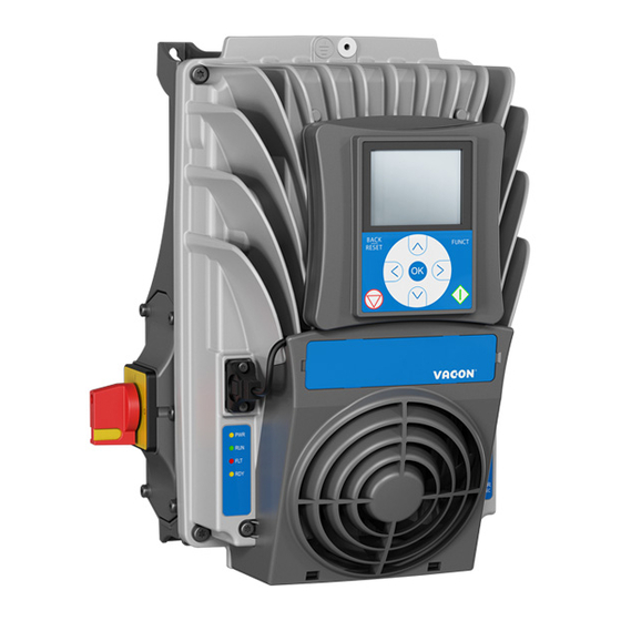
Page 82: Control Keypad
® The control keypad is the interface between the VACON 100 X AC drive and the user. With the con- trol keypad it is possible to control the speed of a motor, to supervise the state of the equipment and to set the AC drive's parameters. -
Page 83: Installation
Options vacon • 83 8.2.2 Installation • Remove the HMI cap from the drive as shown in the Figure 51. Figure 51. Disconnection of the HMI cap from the drive • Install the keypad holder with a screw as shown in the Figure 52. The metal sheets of the keypad holder have to be mounted under the fan holder as shown in the following figures. - Page 84 • 84 Options • Connect the keypad to the drive and plug the cable on the HMI connector as shown in the Figure 53 and in the Figure 54. • Tighten the fixing screws of the cable connector (0.5 Nm/4.5 lb-in) to the enclosure.
-
Page 85: Wall-Mounting
Options vacon • 85 8.2.3 Wall-mounting The keypad can be mounted on the wall in a convenient location by using the same keypad holder and three screws provided with the keypad option kit. • Fix the keypad holder with three screws to the wall. - Page 86 • 86 Options 11863_00 Figure 56. Display holder dimensions for wall-mounting • Connect and fix the cable to the enclosure of the drive and hold the keypad to the wall. Local contacts: https://www.danfoss.com/en/contact-us/contacts-list/...
- Page 87 Options vacon • 87 Figure 57. Keypad connected to the drive Local contacts: https://www.danfoss.com/en/contact-us/contacts-list/...
-
Page 88: Graphical And Text Keypad
• 88 Options 8.2.4 Graphical and Text keypad There are two keypad types you can choose for your user interface: keypad with graphical display and keypad with text segment display (text keypad). The button section of the keypad is identical for both keypad types. -
Page 89: Vacon® Keypad With Graphical Display
Options vacon • 89 ® 8.2.5 VACON keypad with graphical display The graphical keypad features an LCD display and 9 buttons. 8.2.5.1 Keypad display The keypad display indicates the status of the motor and the drive and any irregularities in motor or drive functions. - Page 90 • 90 Options STOP READY STOP READY STOP READY Start/Stop Setup Rem Control Place Rem Control Place ID:172 M3.2.1 M3.2.1 M3.2.1 Rem Control Place Edit I/O Control FieldbusCTRL KeypadStopButton Help I/O Control BACK RESET Start Function...
- Page 91 Options vacon • 91 Resetting fault Instructions for how to reset a fault can be found in chapter 8.2.7. Function button The FUNCT button is used for four functions: 1. to quickly access the Control page, 2. to easily change between the Local (Keypad) and Remote control places, 3.
- Page 92 • 92 Options STOP READY Keypad STOP Ready Keypad STOP READY Keypad Main Menu Choose action Local/Remote ID:1805 ID:211 Monitor Change direction ( 7 ) FUNCT Local Control page Parameters ( 15 ) Local/Remote Remote Remote ...
-
Page 93: Changing Direction
Options vacon • 93 Changing direction Rotation direction of the motor can quickly be changed by applying the FUNCT button. Chang- NOTE! command is not visible in the menu unless the selected control place is ing direction Local 1. Anywhere in the menu structure, push the Funct button. -
Page 94: Copying Parameters
• 94 Options Copying parameters NOTE: This feature is available with graphical keypad only. The parameter copy function can be used to copy parameters from one drive to another. The parameters are first saved to the keypad, then the keypad is detached and connected to another drive. - Page 95 Options vacon • 95 Help texts The graphical keypad features instant help and information displays for various items. All parameters offer an instant help display. Select Help and press the OK button. Text information is also available for faults, alarms and the startup wizard.
-
Page 96: Vacon® Keypad With Text Segment Display
• 96 Options ® 8.2.6 VACON keypad with text segment display You can also choose a (Text keypad) for your user interface. It Keypad with text segment display has mainly the same functionalities as the keypad with graphical display although some of these are somewhat limited. - Page 97 Options vacon • 97 8.2.6.3 Using the keypad Editing values Change value of a parameter following the procedure below: 1. Locate the parameter. 2. Enter the Edit mode by pressing OK. 3. Set new value with the arrow buttons up/down. You can also move from digit to digit with the arrow buttons left/right if the value is numerical and change then the value with the arrow but- tons up/down.
- Page 98 • 98 Options Changing control places Change of control place from (keypad). Remote Local 1. Anywhere in the menu structure, push the FUNCT button. 2. Using the arrow buttons, select Local/Remote and confirm with the OK button. 3. On the next display, select Local or Remote and again confirm with the OK button.
- Page 99 Options vacon • 99 Changing direction Rotation direction of the motor can quickly be changed by applying the FUNCT button. Chang- NOTE! command is not visible in the menu unless the selected control place is ing direction Local 1. Anywhere in the menu structure, push the Funct button.
-
Page 100: Fault Tracing
• 100 Options 8.2.7 Fault Tracing When an unusual operating condition is detected by the AC drive control diagnostics, the drive ini- tiates a notification visible, for example, on the keypad. The keypad will show the code, the name and a short description of the fault or alarm. - Page 101 Options vacon • 101 8.2.7.1 Fault History In menu M4.3 Fault history you find the maximum number of 40 occurred faults. On each fault in the memory you will also find additional information, see below. STOP READY STOP READY STOP READY ...
- Page 102 • 102 Options 8.2.7.2 Fault codes Table 41. Fault codes and descriptions Fault Fault Fault name Possible cause Remedy code Overcurrent AC drive has detected too high a cur- Check loading. (hardware fault) rent (>4 x I ) in the motor cable: Check motor.
- Page 103 Options vacon • 103 Table 41. Fault codes and descriptions Fault Fault Fault name Possible cause Remedy code Communication between control board and power unit has failed. Communication between control board and power unit has interference, but it is still working.
- Page 104 • 104 Options Table 41. Fault codes and descriptions Fault Fault Fault name Possible cause Remedy code Current measurement has detected Output phase that there is no current in one motor Check motor cable and motor. supervision phase. Brake chopper...
- Page 105 Options vacon • 105 Table 41. Fault codes and descriptions Fault Fault Fault name Possible cause Remedy code Check the Safety switch and cabling. Unstable STO input A Safe off Reset the fault and restart. (spurious pulses detected). Should the fault re-occur, con- tact the distributor near to you.
- Page 106 • 106 Options Table 41. Fault codes and descriptions Fault Fault Fault name Possible cause Remedy code At least one of the available analogue Change the failed parts. input signals has gone below 50% of Check the analog input circuit.
- Page 107 Options vacon • 107 Table 41. Fault codes and descriptions Fault Fault Fault name Possible cause Remedy code Maintenance Maintenance counter has reached the Carry out the needed mainte- 1301 counter 1 alarm alarm limit. nance and reset counter. Maintenance...
- Page 108 • 108 Options Table 41. Fault codes and descriptions Fault Fault Fault name Possible cause Remedy code In the Multipump system, 1 or more of Do the necessary maintenance the pump runtime counters is above a 1113 actions, reset the runtime user-specified alarm limit.
-
Page 109: Heater (Arctic Option)
The heater can be used only inside the drive and in combination with only the VACON ® 100 X. Before connecting the heater to mains, make sure that the ® VACON 100 X drive is closed firmly. -
Page 110: Fuses
Table 44. Order codes for VACON 100 X Heater Order code Description Option type ENC-QAFH-MM04 Loose Option ® VACON 100 X MM4 Auxiliary Frame Heater option ENC-QAFH-MM05 Loose Option VACON ® 100 X MM5 Auxiliary Frame Heater option ENC-QAFH-MM06 Loose Option ®... - Page 111 Options vacon • 111 Figure 77. Remove the cable entry plate (right side example) Figure 78. Remove the powerhead from the terminal box Local contacts: https://www.danfoss.com/en/contact-us/contacts-list/...
- Page 112 • 112 Options Figure 79. Connect the supply voltage (black cable) and the output relay (red cable) to the op- tional heater through the bottom cable entry plate. Color of the cables is only an example Figure 80. Mount the optional heater on the terminal box and then close the powerhead...
-
Page 113: Option Boards
® VACON 100 X is an IP66/Type 4X outdoor drive, designed to be installed as close as possible to the motor, minimizing the use of electrical rooms, integrating the drive as part of the machine, without the use of cabinets. - Page 114 ® VACON 100 X drives are products than can be mounted directly onto the motor, machine or wher- ever the most efficient location for the drive is. This solution allows the machine designer, to use the available space in and around the machine, optimally. A decentralized solution provides a more flexible solution as an OEM manufacturer can deliver its machine in one piece, and there is no need to install the drives in a separate location.
- Page 115 Options vacon • 115 Table 46. Correspondences between flange adapters, motors and inverter sizes Rated Power at Inverter Flange adapter current at Motor size 1500 rpm A [mm] B [mm] enclosure order code 1500 rpm [kW] size 2.89 3.67 ENC-QMMF-MM04 100L 2.2/3...
- Page 116 • 116 Options Figure 83. MM5 flange adapter dimensions Figure 84. MM6 flange adapter dimensions Local contacts: https://www.danfoss.com/en/contact-us/contacts-list/...
-
Page 117: Mounting Instructions: Mm4 Example
Options vacon • 117 8.5.1 Mounting instructions: MM4 Example Figure 85. Flange adapter for MM4 Figure 86. Mount the flange adapter on the motor Local contacts: https://www.danfoss.com/en/contact-us/contacts-list/... - Page 118 • 118 Options Figure 87. Mount the drive on the flange adapter using 4 screws NOTE: Recommended screw type: countersunk head. Figure 88. Drive mounted onto the motor Local contacts: https://www.danfoss.com/en/contact-us/contacts-list/...
-
Page 119: Safe Torque Off
This chapter describes the Safe Torque Off (STO) function which is a functional safety feature pres- ® ent into VACON 100 X drive products as standard. General description The STO function brings the motor in no-torque-state as defined by 4.2.2.2 of the IEC 61800-5-2: “Power that can cause rotation (or motion in the case of a linear motor) is not applied to the... -
Page 120: Standards
• 120 Safe Torque Off Standards The STO function has been designed for use in accordance with the following standards: Table 47. Safety Standards Standards IEC 61508, Parts 1-7 EN 61800-5-2 EN 62061 ISO 13849-1 IEC 60204-1 The STO function has to be applied correctly to achieve the desired level of operational safety. Four different levels are allowed, depending on the use of the STO signals (see the following table). -
Page 121: The Principle Of Sto
In VACON ® 100 X, the STO function is realized by preventing the propagation of the control signals to the inverter circuit. The inverter power stage is disabled through redundant disabling paths which start from the two separated and galvanically isolated STO inputs (S1-G1, S2-G2 in Figure 89). -
Page 122: Technical Details
The reaction time of the STO function is the amount of time which passes from the moment in which ® the STO is activated until the system is in the Safe State. For VACON 100 X, the reaction time is 20 ms maximum. -
Page 123: Safety Capability Cat. 4 / Pl E / Sil 3
Safe Torque Off vacon • 123 Figure 90. Removing the STO jumpers Make sure that the AC drive is switched off before cabling. Disconnect both the STO jumpers to allow the cabling of the terminals. When the STO function is used, the IP-class of the drive may not be reduced below IP54. - Page 124 • 124 Safe Torque Off Figure 91. An emergency push button connected to the STO inputs does not assure the same quality, because no fault detection is performed at a sufficient frequency (once a day is recommended). The external safety device, which forces the STO inputs and evaluates the STO output feedback, has to be a safe device and it has to fulfill the requirements of the specific application.
-
Page 125: Safety Capability Cat. 3 / Pl E / Sil 3
Safe Torque Off vacon • 125 Supply EXTERNAL SAFETY DEVICE (**) STO inputs STO feedback POWER UNIT DC+/R+ Reinforced 11867_uk Figure 92. STO example with automatic monitoring of the feedback and both STO inputs used. (**) The external safety device must feed active voltage to the STO inputs. -
Page 126: Safety Capability Cat. 2 / Pl D / Sil 2
• 126 Safe Torque Off 9.5.3 Safety Capability Cat. 2 / PL d / SIL 2 The safety capability is reduced to Cat. 2 / PL d / SIL 2 if the STO inputs are connected in parallel (no redundancy of the STO inputs). -
Page 127: Commissioning
Safe Torque Off vacon • 127 This safety capability can be achieved by connecting in parallel the STO inputs exter- nally and by ignoring the use of the STO output feedback. The following picture shows an example of connection for the STO function. A switch (a safety push button or a safety relay) may be connected with 2 wires to the drive. - Page 128 • 128 Safe Torque Off The wiring must be done according to the general wiring instructions for the specific product. A shielded cable is required. In addition, the voltage drop from the supply point to the load must not exceed 5% [EN 60204-1 part 12.5].
-
Page 129: Checklist For Commissioning
Safe Torque Off vacon • 129 9.6.2 Checklist for commissioning Follow the checklist shown in the table below for the steps required to use the STO function. Table 54. Checklist for commissioning of STO Carry out a risk assessment of the system to ensure that the use of the STO function is safe and according to the local regulations. -
Page 130: Parameters And Fault Tracing
• 130 Safe Torque Off Parameters and fault tracing There are no parameters for the STO function itself. Before testing the STO function, make sure that the checklist (Table 54) is inspected and completed. When STO function activates, the drive always generates a fault (“F30”) and the motor stops by coasting. - Page 131 www.danfoss.com Document ID: DPD00534M Danfoss Drives Oy Rev. M Runsorintie 7 65380 Vaasa Finland...
Need help?
Do you have a question about the 100 x and is the answer not in the manual?
Questions and answers