
Related Manuals for Vacon Vacon 20 Series


Summary of Contents for Vacon Vacon 20 Series
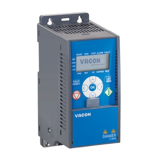
- Page 1 ® ac drives quick guide Buy: www.ValinOnline.com | Phone 844-385-3099 | Email: CustomerService@valin.com...
- Page 2 Buy: www.ValinOnline.com | Phone 844-385-3099 | Email: CustomerService@valin.com...
- Page 3 The motor terminals U, V, W (T1, T2, T3) and the possible brake resistor terminals - / + are live when Vacon 20 is connected to mains, even if the motor is not running. The control I / O-terminals are isolated from the mains poten- tial.
- Page 4 • vacon safety Buy: www.ValinOnline.com | Phone 844-385-3099 | Email: CustomerService@valin.com...
- Page 5 • installation vacon 2. INSTALLATION 2.1 Mechanical installation There are two possible ways to mount Vacon 20 in the wall. For MI1 - MI3, either screw or DIN-rail mounting; For MI4 - MI5, screw or flange mounting. BACK BACK RESET...
- Page 6 Leave free space for cooling above (100 mm), below (50 mm), and on the sides (20 mm) of Vacon 20! (For MI1 - MI3, side-to-side installation allowed only if the am- bient temperature is below 40 °C; For MI4 - MI5, side-to-side installation is not al- lowed.
- Page 7 • installation vacon Drive outline Opening outline Figure 5: Flange mounting cutout dimensions for MI4 (Unit: mm) Drive outline Opening outline Figure 6: Flange mounting cutout dimensions for MI5 (Unit: mm) Buy: www.ValinOnline.com | Phone 844-385-3099 | Email: CustomerService@valin.com...
- Page 8 • vacon installation Figure 7: Flange mounting depth dimensions for MI4 and MI5 (Unit: mm) Buy: www.ValinOnline.com | Phone 844-385-3099 | Email: CustomerService@valin.com...
- Page 9 • installation vacon Attach the support AFTER installing the power cables Attach this plate BEFORE installing the power cables Figure 8: Attaching the PE-plate and API cable support, MI1 - MI3 Attach the support AFTER installing Attach this plate BEFORE installing...
- Page 10 Mot or out L1 L2/N L3 R+ R- U/ T1 V/T2 W/T3 Strip the plastic cable coating for 360° earthing BRAKE MAINS MOTOR RESISTOR Figure 11: Vacon 20 power connections, MI2 - MI3 Buy: www.ValinOnline.com | Phone 844-385-3099 | Email: CustomerService@valin.com...
- Page 11 3~ (380, 480V) Motor out Brake RESISTOR MOTOR MAINS Figure 12: Vacon 20 power connections, MI4 3~ (380, 480V) Motor out Brake MAINS MOTOR RESISTOR Figure 13: Vacon 20 power connections, MI5 Buy: www.ValinOnline.com | Phone 844-385-3099 | Email: CustomerService@valin.com...
- Page 12 • vacon installation 2.2.2 Control cabling Figure 14: Open the lid MI1 - MI3 Figure 15: Open the lid MI4 - MI5 Buy: www.ValinOnline.com | Phone 844-385-3099 | Email: CustomerService@valin.com...
- Page 13 • installation vacon Control cable tightening torque: 0.4 Nm Strip the plastic cable coating for 360°earthing Figure 16: Install the control cables, MI1 - MI3 Figure 17: Install the control cables, MI4 - MI5 Buy: www.ValinOnline.com | Phone 844-385-3099 | Email: CustomerService@valin.com...
- Page 14 • vacon installation 2.2.3 Allowed option boards in Vacon20 See below for the allowed option boards in the slot: Note! OPT-B1 and OPT-B4 only support external power supply. Option board assembly structure: Buy: www.ValinOnline.com | Phone 844-385-3099 | Email: CustomerService@valin.com...
- Page 15 • installation vacon Buy: www.ValinOnline.com | Phone 844-385-3099 | Email: CustomerService@valin.com...
- Page 16 • vacon installation Buy: www.ValinOnline.com | Phone 844-385-3099 | Email: CustomerService@valin.com...
- Page 17 20 DO Digital signal out Active = READY 48 V / 50 mA Table 1: Vacon 20 General purpose application default I / O configuration and connections for control board P) = Programmable function, See User Manual: parameter lists and descriptions for detail Buy: www.ValinOnline.com | Phone 844-385-3099 | Email: CustomerService@valin.com...
- Page 18 250 Vac / 2 A or 250 Vdc / Active = FAULT 0.4 A 26 RO 24 Table 1: Vacon 20 General purpose application default I / O configuration and connections for control board P) = Programmable function, See User Manual: parameter lists and...
- Page 19 • navigation & startup vacon 4. NAVIGATION AND STARTUP 4. 1 The main menus of Vacon 20 R E A D Y R U N S T OP A L AR M FA U LT R E A D Y...
- Page 20 Table 3: Commissioning steps 4.2.2 Startup wizard Vacon 20 runs the startup wizard in first power-up. The wizard can be run by setting SYS Par.4.2 =1. The following figures show the procedure. NOTE! Running the startup wizard will always return all parameter...
- Page 21 • navigation & startup vacon READ Y RUN STOP ALARM FAU LT READ Y RUN STOP ALARM FAU LT READ Y RUN STOP ALARM FAU LT FWD REV I/O KEY PAD BUS FWD REV I/O KEY PAD BUS FWD REV...
- Page 22 • vacon navigation & startup Buy: www.ValinOnline.com | Phone 844-385-3099 | Email: CustomerService@valin.com...
- Page 23 & parameters vacon 5. MONITORING AND PARAMETERS NOTE! This guide is for Vacon 20 standard application, if you need parameter de- scriptions for detail, please download the user manual on Vacon website -> Support & downloads. 5.1 Monitoring values...
- Page 24 • vacon monitoring & parameters Code Monitoring signal Unit Description Analogue input signal 1 in % from V2.11 Analogue input E1 option board, hidden until an option board is connected Analogue output signal 1 in % from V2.12 Analogue output E1...
- Page 25 • monitoring & parameters vacon Code Monitoring signal Unit Description Bit codes status of drive B0 = Ready B1 = Run B2 = Reverse V3.1 Drive status word B3 = Fault B6 = RunEnable B7 = AlarmActive B12 = RunRequest...
- Page 26 • vacon monitoring & parameters 5.2 Quick setup parameters (Virtual menu, shows when par. 17.2 = 1) Code Parameter Unit Default Note Motor nominal Check rating plate on the Varies P1.1 voltage motor. Motor nominal 50.00 / Check rating plate on the 30.00 320.00...
-
Page 27: Table Of Contents
• monitoring & parameters vacon Code Parameter Unit Default Note Preset speed 0 is used P3.4 Preset speed 0 P3.1 P3.2 5.00 as frequency reference when P3.3 = 1 Activated by digital P3.5 Preset speed 1 P3.1 P3.2 10.00 inputs Activated by digital P3.6... - Page 28 • vacon monitoring & parameters 5.3 Motor settings (Control panel: Menu PAR -> P1) Code Parameter Unit Default Note Motor nominal Check rating plate on the Varies P1.1 voltage motor 50.00 / Motor nominal Check rating plate on the 30.00 320.00 P1.2...
- Page 29 • monitoring & parameters vacon Code Parameter Unit Default Note 0 = Disabled Brake Chopper 1 = Enabled: Always P1.17 2 = Run state Brake chopper control acti- vation level in volt. For 240V Supply: 240*1.35*1.18 = 382V For 400V Supply: 400*1.35*1.18 = 638V...
- Page 30 • vacon monitoring & parameters 5.4 Start / stop setup (Control panel: Menu PAR -> P2) Code Parameter Min Max Unit Default Note 0 = I / O terminals Remote Control P2.1 1 = Fieldbus Place Selection 2 = Keypad...
-
Page 31: P3.4 Preset Speed
• monitoring & parameters vacon 5.5 Frequency references (Control panel: Menu PAR -> P3) Code Parameter Unit Default Note Minimum allowed Min frequency 0.00 P3.2 0.00 P3.1 frequency reference Maximum allowed 50.00 / Max frequency P3.1 320.00 P3.2 60.00... -
Page 32: P4.2 Acceleration Time
• vacon monitoring & parameters 5.6 Ramps and brakes setup (Control panel: Menu PAR -> P4) Code Parameter Unit Default Note 0 = Linear Ramp S-shape 1 10.0 P4.1 >0 = S-curve ramp time Defines the time required for the output Acceleration time 1 3000.0... - Page 33 • monitoring & parameters vacon Code Parameter Unit Default Note Accel2 Frequency P4.13 0.00 P3.2 0.00 527 0.00 = disabled Threshold Decel2 Frequency P4.14 0.00 P3.2 0.00 528 0.00 = disabled Threshold Delay to open brake External Brake: P4.15 0.00 320.00...
- Page 34 • vacon monitoring & parameters 5.7 Digital inputs (Control panel: Menu PAR -> P5) Code Parameter Unit Default Note 0 = Not used 1 = DI1 2 = DI2 3 = DI3 4 = DI4 5 = DI5 P5.1 I / O control signal 1...
- Page 35 • monitoring & parameters vacon Code Parameter Unit Default Note Activates reference 2 P5.16 PID setpoint 2 Varies 1047 See 5.1 Activates the Motor Pre- heat (DC-Current) in Motor Preheat stop state when parame- P5.17 Varies 1044 Active ter Motor Preheat func- tion is set to 2 See 5.1...
- Page 36 • vacon monitoring & parameters 5.9 Pulse train / Encoder (Control panel: Menu PAR -> P7) Code Parameter Unit Default Note Pulse frequency to be Min pulse fre- P7.1 10000 1229 interpreted as a 0% sig- quency nal. Pulse frequency to be Max pulse fre- P7.2...
- Page 37 • monitoring & parameters vacon 5.10 Digital outputs (Control panel: Menu PAR -> P8) Code Parameter Unit Default Selections 0 = Not used 1 = Ready 2 = Run 3 = Fault 4 = Fault Inverted 5 = Warning 6 = Reversed...
- Page 38 • vacon monitoring & parameters Code Parameter Unit Default Selections DOE4 signal See 8.1, hidden until an P8.13 Varies 1390 selection option board is connected DOE5 signal See 8.1, hidden until an P8.14 Varies 1391 selection option board is connected DOE6 signal See 8.1, hidden until an...
- Page 39 • monitoring & parameters vacon Code Parameter Unit Default ID Selections Analogue output See P9.3, hidden until an P9.7 1000.0 100.0 E1 scaling option board is connected Analogue output See P9.4, hidden until an P9.8 0.00 10.00 0.10 E1 filter time...
- Page 40 • vacon monitoring & parameters 5.12 Fieldbus Data-Mapping (Control panel: Menu PAR -> P10) Code Parameter Unit Default Note 0 = Frequency reference 1 = Output reference 2 = Motor speed 3 = Motor current 4 = Motor voltage 5 = Motor torque...
- Page 41 • monitoring & parameters vacon 5.13 Prohibited Frequencies (Control panel: Menu PAR -> P11) Code Parameter Unit Default Note Prohibit Frequency Low Limit P11.1 0.00 P3.2 0.00 Range 1 Low Limit 0.00 = Not used Prohibit Frequency High Limit P11.2 0.00...
- Page 42 • vacon monitoring & parameters Code Parameter Unit Default Note Binary-coded selection of signals to use for tem- perature supervision B0 = Temperature input 1 Temperature P12.10 1431 B1 = Temperature input 2 supervision input B2 = Temperature input 3...
- Page 43 • monitoring & parameters vacon Code Parameter Unit Default Note Mtp:Ambient Environment tempera- °C P13.8 temperature tion Mtp:Zero speed 150.0 40.0 706 Cooling as % at 0 speed P13.9 cooling Mtp:Thermal time Motor thermal time con- Varies P13.10 constant stant For a stall stage to 2.0 x...
- Page 44 • vacon monitoring & parameters Code Parameter Unit Default Note See P13.3, hidden until P13.24 Temperature fault an OPTBH board is con- nected Binary-coded selection of signals to use for alarm and fault trigger- Temperature fault B0 = Temperature input 1 P13.25...
- Page 45 • monitoring & parameters vacon 5.17 PID control parameters (Control panel: Menu PAR -> P15) Code Parameter Unit Default Note 0 = Fixed setpoint % 1 = AI1 2 = AI2 3 = ProcessDataIn1 (0 -100%) 4 = ProcessDataIn2 (0 -100%)
- Page 46 • vacon monitoring & parameters Code Parameter Unit Default Note P15.9 D time 0.00 10.00 0.00 132 Derivative time 0 = Direct (Feedback < Set- point ->Increase PID out- put) P15.10 Error inversion 1 = Inverted (Feedback > Setpoint ->Decrease PID...
- Page 47 • monitoring & parameters vacon Code Parameter Unit Default Note Temperature min value for Temperature -50.0/ PID and frequency refer- P15.22 P15.23 1706 min value 223.2 ence scale, hidden until an OPTBH board is connected Temperature max value for Temperature 200.0/...
- Page 48 • vacon monitoring & parameters 5.20 System parameters Code Parameter Min Max Default Note Software information (MENU PAR -> V1) V1.1 API SW ID 2314 V1.2 API SW version V1.3 Power SW ID 2315 V1.4 Power SW version V1.5 Application ID V1.6...
- Page 49 • monitoring & parameters vacon Code Parameter Min Max Default Note 0 = None 1 = Even 2 = Odd The Stop Bit is 2-bit P2.6 Parity type When Parity type is 0 = None; The Stop Bit is 1-bit...
- Page 50 • vacon monitoring & parameters Code Parameter Min Max Default Note Status of Modbus communication. Format: XXXX.Y, X = DeviceNet msg counter V2.1 Communication status 14014 Y = DeviceNet status 0 = Non-existent or no bus power 1 = Configuring state...
- Page 51 • monitoring & parameters vacon Code Parameter Min Max Default Note 0 = No Sensor 1 = PT100 2 = PT1000 P2.2 Sensor 2 type 14073 3 = Ni1000 4 = KTY84 5 = 2 x PT100 6 = 3 x PT100...
- Page 52 • vacon monitoring & parameters Buy: www.ValinOnline.com | Phone 844-385-3099 | Email: CustomerService@valin.com...
- Page 53 • FAULT TRACING vacon 6. FAULT TRACING Fault code Fault name Fault code Fault name Overcurrent Back EMF protection Overvoltage Thermistor fault Internal bus communica- Earth fault tion System fault Application fault Undervoltage IGBT Overtemperature Analogue input select 20% - 100% (selected signal...
- Page 54 • vacon FAULT TRACING Buy: www.ValinOnline.com | Phone 844-385-3099 | Email: CustomerService@valin.com...
- Page 55 10.3 14.6 17.6 16.3 Vacon 20 units with other than EMC4 filter combinations cannot be Networks used on delta power networks (corner grounded) Supply Maximum short circuit current has to be < 50 kA, For MI4 without network Short circuit cur- DC-choke, maximum short circuit current has to be <...
- Page 56 Cu (mm Control Main Earth and relay Cable and fuse 3*1.5+1.5 1.5-4 requirements (See detailed data in Vacon 20 User 3*2.5+2.5 1.5-6 Manual at: Vacon website) 380 - 480 V, 3~ 208 – 240 V, 3~ 3*6+6 1-10Cu 1-10 (20 and 40 is...
- Page 57 26.3 20.6 0025 37.5 30.3 0031 46.5 36.6 0038 44.6 Table 26: Vacon 20 power ratings, 208 - 240 V, 3~ *The maximum ambient operating temperature of this drive is +40°C ! Buy: www.ValinOnline.com | Phone 844-385-3099 | Email: CustomerService@valin.com...
- Page 58 0005 0006 0008 11.4 0.99 0009 13.5 11.5 0.99 0012 14.9 0.99 0016 17.1 0023 34.5 25.5 0031 46.5 0038 18.5 41.7 Table 28: Vacon 20 power ratings, 380 - 480 V Buy: www.ValinOnline.com | Phone 844-385-3099 | Email: CustomerService@valin.com...
- Page 59 0009 13.5 10.4 0.99 Table 29: Vacon 20 power ratings, 575 V Note: The input currents are calculated values with 100 kVA line transformer supply. Quick Modbus setup A: Select Fieldbus as remote control place: P2.1 to1 – Fieldbus B: Set Modbus RTU protocol to “ON”: SYS P2.2 to 1 – Modbus A.
- Page 60 Document ID: Finland Subject to change without prior notice © 2013 Vacon Plc. Rev. E1 Buy: www.ValinOnline.com | Phone 844-385-3099 | Email: CustomerService@valin.com...
Need help?
Do you have a question about the Vacon 20 Series and is the answer not in the manual?
Questions and answers