Bray 70 Series Manual
- Installation, operation and maintenance manual (48 pages) ,
- Operation and maintenance manual (30 pages) ,
- Technical manual (8 pages)
Advertisement
- 1 DEFINITION OF TERMS
- 2 STORAGE
- 3 OPERATING YOUR ACTUATOR
- 4 MOUNTING THE ACTUATOR
-
5
COMMISSIONING
- 5.1 WIRING YOUR ACTUATOR
- 5.2 SETTING TRAVEL LIMIT SWITCHES CAMS
- 5.3 SETTING MECHANICAL TRAVEL STOPS
- 5.4 CONFIGURING YOUR 24V ON/OFF CONTROLLER
- 5.5 CHANGING SETTINGS
- 5.6 CLOSE SPEED CONTROL
- 5.7 OPEN SPEED CONTROL
- 5.8 DEAD BAND CONTROL
- 5.9 Torque Switch Detection
- 5.10 Reverse Acting Mode
- 5.11 Operating Modes
- 5.12 Status Indication
- 5.13 Valve Position
- 5.14 Fault Status
- 5.15 Bray Logo
- 6 FIELD OR FACTORY INSTALLABLE OPTIONS
- 7 TROUBLESHOOTING GUIDE
- 8 ACTUATOR TROUBLESHOOTING CHART
- 9 TROUBLESHOOTING EXAMPLE
- 10 BASIC TOOLS
- 11 SAFETY
- 12 Documents / Resources
DEFINITION OF TERMS

Indicates a potentially hazardous situation which, if not avoided, could result in death or serious injury.

Indicates a potentially hazardous situation which, if not avoided, may result in minor or moderate injury.
NOTICE
Indicates a potentially hazardous situation which, if not avoided, may result in minor or moderate injury.
STORAGE
- Store units on a shelf or wooden pallet in order to protect against floor dampness.
- Cover the units to protect against dust and dirt.
- To prevent condensation inside these units, maintain a near constant external temperature and store in a well-ventilated, clean, dry room away from vibration. For units with an internal heater, power should be supplied to the heater via conduit entry with an appropriate sealing gland.
Actuators are not weatherproof unless they are properly installed on the valve or prepared for storage. Bray will not accept responsibility for deterioration caused on-site.
OPERATING YOUR ACTUATOR
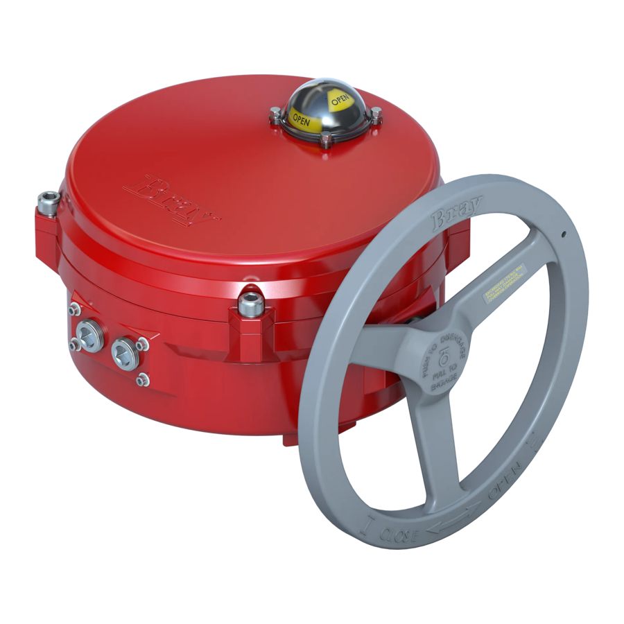
OPERATING BY HAND
- To engage the manual override, simply pull the handwheel to its outermost position. A yellow stripe is revealed to visually indicate manual override engagement as shown in Figure 1.

- Once the manual override is engaged, rotating the handwheel in the clockwise direction will rotate the output shaft in the clockwise (close) direction and vice-versa.
- To disengage the manual override, the handhwheel needs to be pushed towards the actuator until the 'yellow stripe' is hidden.

A label on the handwheel hub warns users not to exceed a specific 'rim pull' force, for each size of actuator. If the 'rim pull' force is exceeded, the roll pin securing the handwheel onto the manual override shaft is designed to shear, thus preventing serious internal gearing damage.
OPERATING ELECTRICALLY
- To control the actuator remotely from a process controller, user must apply 24 VAC or 24 VDC to the actuator. This control signal voltage can be applied locally or remotely from a process controller.
![]()
Verify that the main electric power supplied to the actuator is in compliance with the specifications on the actuator label - Engaging the handwheel before or during the application of a control signal voltage will prevent the actuator motor from operating.
- If torque switches are installed in the actuator, an overtorque condition will also prevent the actuator motor from operating.
MOUNTING THE ACTUATOR
- All Bray Series 70 electric actuators are suitable for direct mounting on Bray butterfly valves. With proper mounting hardware, the S70 actuator can be installed onto other quarter-turn valves or devices as well.
NOTICE
The standard mounting position for the actuator is to orient the base of the actuator parallel to the pipeline. If the actuator is to be mounted on a vertical pipe, it is recommended that the unit be positioned with the conduit entries on the bottom to prevent condensation entering the actuator through its conduits. - Follow the steps below to mount the actuator onto the valve.
- Manually operate the actuator until the output shaft of the actuator is in line with the valve stem. If possible, select an intermediate position for both the valve and actuator.
- If required, place the proper adapter onto the valve stem. It is recommended that a small amount of 'anti-seize' lubricant be applied to the adapter to ease assembly.
- Mount the actuator onto the valve stem. It may be necessary to operate the actuator manually to align the valve and actuator bolt patterns.
- Install the furnished mounting studs by threading them all the way into the actuator base.
- Fasten the mounting studs in place with furnished hex nuts and lock washers.
COMMISSIONING
WIRING YOUR ACTUATOR

Turn off all power and lockout/tagout service panel before installing or modifying any electrical wiring.
- Take the actuator cover off and place it in a safe location.
- Each actuator is provided with two conduit entries. Use one for power and the other for control wiring.
- Wire the actuator as per the wiring diagram attached to the inside of the actuator cover.
NOTICE
- A minimum of 18 AWG wire is recommended for all field wiring.
- The terminals on the actuator switch plate, On/Off Controller or Servo NXT accepts wire sizes ranging from 14 to 22 AWG.
- The conduit connections must be properly sealed to maintain the weatherproof integrity of the actuator enclosure.

Figure 2. Sample field wiring diagram for Series 70 24V On/Off Actuator with auxiliary switches
SETTING TRAVEL LIMIT SWITCHES CAMS
- Bray uses its patented cam design along with 2 SPDT mechanical switches to set the 'Open' and 'Close' position of the valve.
- The green cam actuates the 'open' switch when the actuator reaches the 'open' position. Similarly, the red cam actuates the 'close' switch when the actuator reaches the 'close' position.
- Standard factory setting of the travel limit switches allows 90° travel between open and close positions. Cams for each switch are adjustable for applications where less than 90° degree travel is desired between the open and closed positions.

Figure 3. Two SPDT Travel Limit Switches - Follow the steps below to adjust the travel limit cams.
- Remove the indicator rotor by pulling it away from the indicator shaft as shown in Figure 4.
![]()
Figure 4. Indicator rotor pulled up from the indicator shaft - Manually operate the actuator clockwise until the valve reaches the desired 'close' position.
- Loosen the cam locking screw shown in Figure 5.

Figure 5. Top view of the indicator cam shaft
NOTE: It is possible that the rotation of one cam will move the other cam. If this occurs, hold the other knobs or cams during adjustment. - Rotate the red cam adjustment knob by hand or with a flat head screwdriver until the red cam lobe activates (depresses) the 'close' switch from a clockwise direction.
- Manually operate the actuator counterclockwise until the valve reaches the desired 'open' position.
- Rotate the green cam adjustment knob until the green cam lobe activates (depresses) the 'open' switch from a counterclockwise direction.
- After both travel switch adjustments have been completed, tighten the cam locking screw and place the indicator rotor back on the indicator shaft.
- Remove the indicator rotor by pulling it away from the indicator shaft as shown in Figure 4.


SETTING MECHANICAL TRAVEL STOPS
- Mechanical travel stops are designed to prevent overtravel while manually operating the actuator. They are not designed to stop the electric motor.
- Mechanical travel stops are located outside the actuator base for easy readjustment. Stainless steel lock nuts with O-ring seals hold the travel stops securely in place as shown in Figure 6.
![]()
Figure 6. Mechanical Travel Stops (CW Close). - Follow the steps below to set the mechanical travels stops.
- Manually drive the actuator to the closed position.
- Once the actuator is in the closed position, rotate the handwheel clockwise:
- ½ turn for Housing Size 6.
- 1 turn for Housing Size 12.
- ½ turn for Housing Size 30.
NOTE:Maximum Actuator Torque Housing Size 600 Lb-In 6 2000 Lb-In 12 5000 Lb-In 30
- Adjust the closed travel stop bolt until it contacts the output segment gear and lock it in position with the locknut.
- Manually drive the actuator to the open position.
- Once the actuator is in the open posiiton, rotate the handwheel counterclockwise:
- ½ turn for Housing Size 6.
- 1 turn for Housing Size 12.
- ½ turn for Housing Size 30.
- Adjust the open travel stop bolt until it contacts the output segment gear and lock it in position with the locknut.

CONFIGURING YOUR 24V ON/OFF CONTROLLER
- Every Series 70 24V On/Off Actuator is fitted with a 24V On/Off Controller as shown in Figure 7.
- Figure 7. S70 24V On/Off Actuator

- The 24V On/Off Controller offers 3-wire control for the actuator.
- The 24V On/Off Controller features a rich, LED-based menu that displays both configurable settings and operational status indicators are grouped together based on function, shown by their respective label(s).
- The product settings determine how the 24V On/Off Controller will respond to commands from the process controller. These must be defined and verified before operation begins. The settings that can be adjusted on the 24V On/Off are, in clockwise order:
- "Close Speed" – Close Speed Control > "Open Speed" – Open Speed Control
- "Dead Band" – Dead Band Control
- "Torque Switch" – Torque Switch Detection
- "Reverse Acting" – Reverse Acting Mode
- All units ship with default settings from the factory.
Figure 9: 24V On/Off default settingsFeature Setting Open Speed Control 100% Close Speed Control 100% Dead Band Control 3% Torque Switch Detection Off Reverse Acting Mode Off - To drive the actuator in the open direction, 24 VDC or 24 VAC power must be applied between the "Open" and "Common" terminals of the controller
- Similarly, to drive the actuator in the close direction, 24VDC or 24VAC power must be applied to the 'Close' and 'Common' terminals of the controller.
- When the command signal is first applied, the Controller will wait for 1 second before powering the actuator motor. This delay is necessary to prevent a simultaneous reversal of the motor if an abrupt change in command signal direction occurs (instant reverse delay).
- Once the actuator has reached the 'Open' or 'Close' position, the travel limit switch is activated and the controller turns off power to the motor.
- NOTICE
Verify that the main electric power supplied to the actuator is in compliance with the specifications on the product label

CHANGING SETTINGS
- Settings can be changed locally by utilizing the keypad on the 24V On/ Off. The keypad is located on the right side of the unit, and the keys are labelled based on the operation performed.
- Up arrow - Cycles the cursor (see below) in a counter-clockwise direction
- Down arrow - Cycles the cursor in a clockwise direction
- Check mark - Activates the selected setting (if applicable) and saves the current configuration
- Settings are changed using the cursor, visualized by a flashing indicator. To produce the cursor, the up or down arrow key must be pressed, causing one of the setting indicators to flash. Pressing or holding the Up or Down Arrow will move the cursor in the respective direction, as illustrated in Figure 3. Producing the cursor does not alter any settings without further user input, and the cursor will automatically timeout if the keypad is not used.
- Once the cursor has been positioned over a desired setting, pressing and holding the check mark for 1 second or more will activate the selected setting. Attempting to activate a setting that is already active will have no additional effect.
CLOSE SPEED CONTROL
- Close Speed Control determines how quickly the 24V On/Off operates the actuator in the close direction. This value is a percentage of the full speed. The illuminated indicators act as a level gauge: activating a speed setting illuminates all lower speed setting indicators. Maximum speed illuminates all indicators, while minimum speed illuminates only one.
- Figure 8. 24V On/Off Close Spped Settings
Close Speed Setting Description 0% - 100% (default) Step size: 20% Actuator close speed as a percentage of full speed
OPEN SPEED CONTROL
- Open Speed Control determines how quickly the 24V On/Off operates the actuator in the open direction. This value is a percentage of the full speed. The illuminated indicators act as a level gauge: activating a speed setting illuminates all lower speed setting indicators. Maximum speed illuminates all indicators, while minimum speed illuminates only one.
- Figure 9. 24V On/Off Open Speed Settings
Open Speed Setting Description 0% - 100% (default)
Step size: 20%Actuator open speed as a percentage of full speed
DEAD BAND CONTROL
- Dead Band Control determines the acceptable offset between the position command provided by the input command and the current position of the actuator, determined from the feedback signal provided by the potentiometer. This value is a percentage of the full input range, and creates an inactive area centered around the desired set point. For example, for a 0-10V input command, a 2% Dead Band Control setting allows the actuator position to be offset from the desired set point by up to 0.1V in either direction, creating a dead band with a span of 0.2V. The illuminated indicators act as a level gauge: activating a dead band setting illuminates all lower dead band setting indicators. Maximum dead band illuminates all indicators, while minimum dead band illuminates only one.
- Figure 10. 24V On/Off Dead Band Setting
Dead Band Setting Description 1% - 6%
3% (default)
Step size: 1%Acceptable offset between command position and actuator position
Torque Switch Detection
- Torque Switch Detection determines whether the 24V On/Off is responding to changes to the torque switch assembly. When on, the 24V On/Off will stop the actuator if a torque switch is engaged, signaling that the actuator is operating at torques above its rated torque. This setting should only be activated if torque switches are connected to the 24V On/Off.
- Figure 11. 24V On/Off Torque Switch Settings
Torque Switch Setting Description On Actuator movement stopped if the torque switch engages Off (default) Torque switch state ignored
Reverse Acting Mode
- Reverse Acting Mode determines how the 24V On/Off responds to input commands. When on, the 24V On/Off will operate inversely to how it operates normally, treating the maximum input signal value as the close command and the minimum input signal as the open command. This setting does not affect the output signal.
- Figure 12 24V On/Off Reverse Acting Mode Settings
Reverse Acting Setting Description On 24V On/Off responds inversely to input commands Off (default) 24V On/Off responds normally to input commands
Operating Modes
Remote Mode
By default, the operating mode of the 24V On/Off is remote mode, where the valve is positioned based on input signals. Exiting another mode of operation generally results in the 24V On/Off returning to remote mode.
Local Mode
Local Mode is entered if a connection is made to the Control Box terminals and a command signal is present. This allows the 24V On/ Off to be controlled by a local control box, mounted to or near the actuator. See the section on the control box for more information.
Manual Mode
This operating mode allows for the actuator to be controlled directly from the user interface on the 24V On/Off. By utilizing the keypad, the user can change the position of the valve with a single button press.
Manual mode is exited in the same way it is entered: by pressing and holding the manual mode button for 1 second. While in manual mode, the indicator next to the manual mode button remains lit. Manual mode can only be entered during remote operation.
- Up arrow – Energizes the actuator in the open direction. The actuator will operate until it reaches the end of travel.
- Down arrow - Energizes the actuator in the close direction. The actuator will operate until it reaches the end of travel.
Status Indication
These are all indicators that report key information on the operation and functional status of the 24V On/Off and actuator.
Valve Position
The indicators provides position information of the valve under control.
- Position indicators – The indicators act as a level gauge, with the fully closed position serving as the zero point. Indicator will flash which represents the command signal. Once the actuator reaches the command signal set point, the single command signal indicator will stop flashing. This scheme provides the operator an indication of both the command signal and actuator position using a single display.
Fault Status
- These indicators in the lower left of the user interface illuminate in the event of a fault. The occurrence of a fault generally indicates that user intervention is required to restore operation, and these indicators attempt to provide the diagnostic information needed to accomplish this.
- The Fault Status indicators are, from left to right:
- Limit Switch – Both travel limit switches have been engaged, preventing the actuator from operating, or the travel limit switches are not correctly wired to the 24V On/Off.
- Hand Wheel – The actuator handwheel has been engaged (pulled out), or the handwheel switch is not correctly wired to the 24V On/ Off.
- Torque Switch – A torque switch has been engaged, or the torque switches are not correctly wired to the 24V On/Off.
- In addition, all the fault indicators can be flashing in unison. During autocalibration, this means that the autocalibration sequence has failed. During normal operation, this indicates that a motor stall fault has occurred. Refer to the section on Motor Stall Detection for more detail on a motor stall fault.
- Refer to the Troubleshooting section for the actions required to clear a fault.
Bray Logo
- The indicators that illuminate the Bray logo in the lower right of the user interface serve as status indicators for the 24V On/Off. No matter what operation is performed, these indicators should be flashing on and off. If they are not flashing, refer to the Troubleshooting section.

- The LED flash codes for the 24V On/Off Controller are described in Table 2 below.
Table 2
| LED Behavior | Meaning |
| 'Pwr' LED flashes green every ½ second | The actuator has power and is operational. |
| 'Fault' LED glows red | Hand-wheel is engaged/pulled out |
| The Open or Close Torque switch is engaged | |
| Both the travel limit switches are engaged at the same time | |
| 'Open' LED glows green | Actuator is being driven in the open direction. |
| 'Close' LED glows red | Actuator is being driven in the close direction |
FIELD OR FACTORY INSTALLABLE OPTIONS
HEATER
- To prevent condensation from forming inside the actuator, Bray offers an optional heater as a field or a factory installable option.
- The heater is thermostatically controlled. It self-regulates by increasing or decreasing its electrical resistance relative to its temperature.
- Figure 12. Heater installed on an S70
![]()
- NOTICE

- The heater must have a constant power supply to be effective.
- The heater surface can reach temperatures in excess of 200°Celsius.
![]()
The heater surface can reach temperatures in excess of 200°Celsius
CONTROL STATION
- Bray's Control Station gives the operator the ability to locally drive the actuator with electrical power; overriding the control signal from the process controller.
- The control station has a red (close) and green (open) light to provide end of travel indication. It also has two 3-position switches as shown in Figure 11.
- Figure 13. S70 with the Control Station

- Switch 1 lets the operator choose between the following three modes of operation:
- Local: In this mode, using switch 2 the operator can drive the actuator to open or close position, or stop the actuator; overriding any control signal from the process controller.
- Off: In this mode, the actuator can only be operated manually.
- Remote: In this mode, the Actuator is controlled remotely from a process controller using a 24 VDC or 24 VAC signa
- NOTE:
- Control Station can also be ordered with key lockable switches.
- Control Station requires a dedicated set of auxiliary switches. These switches are required for turning on or off the lights on the control station to locally indicate actuator position.
- Control Station does not contain terminal strips. All wiring is done directly to the switches and lights via 2 x 3/4" NPT holes in the bottom of the control station housing. Wire the process controller to the control station in accordance to the wiring diagram provided.
- Ordering the Control Station with optional pin connector receptacles will eliminate the necessity of field wiring

AUXILLIARY SWITCHES
- Auxiliary switches are a pair of dry-contact (voltage free) SPDT mechanical switches used to indicate travel position to remote customer control systems.
- Figure 14. Fixed auxillary switches installed in an actuator

- NOTE:
- Fixed Auxiliary switches activate 3° before the travel limit switches. They are available as a factory and field installable option.
- Adjustable auxiliary switches can be set to any position. They are available as a factory or field installable option.

TORQUE SWITCHES
- Mechanical Torque switches are designed to interrupt power to the motor windings when the actuator torque exceeds the calibrated factory setting.
- Mechanical Torque switches are a factory installed and calibrated option available for all Series 70 units.
BATTERY BACKUP UNIT
- To meet customer needs, Bray offers a Battery Backup Unit (BBU) for the 24 V Series 70 Electric Actuator.
- In the event of power failure, the BBU will switch the actuator to battery power to reach its fail position. After the actuator has reached its fail position, the BBU goes to 'Standby Mode' until external power is restored.
- Once external power has been restored, the actuator returns to the position corresponding to the control signal present.
- Figure 15. S70 with Battery Backup Unit
![]()
- Battery Backup Unit is available as a factory installable option. For more information, please refer to the 'S70 24V Actuator with BBU' Manual.

SPINNER
- A spinner is available as an attachment to the actuator handwheel to ease and speed the manual operation of the actuator.
- Figure 16. S70 with Handwheel Spinner Attached
![]()
- NOTE:
Care should be exercised in the use of spinner equipped handwheels. Rapid operation of the handwheel to close the valve may cause water hammer. Rapid travel into a travel stop may also cause damage.

RECEPTACLES (QUICK CONNECTORS)
- For quick and easy field wiring, Bray offers plug-in receptacles.
Cordsets to fit these connectors can also be ordered in several lengths. - Figure 17. S70 with a 5 pin receptacle and the corresponding cordset.
![]()

TROUBLESHOOTING GUIDE
- The Series 70 24V On/Off actuator is easy to configure and operate, but if problems do occur, the following guide can assist in troubleshooting.
- The first step is to observe the 'Pwr' LED on the 24V On/Off Controller to verify that proper electrical power has been connected. If the 'Pwr' LED is flashing green, it means that the actuator has been powered correctly.
- Next, observe the Fault LED. If the 'Fault' LED on the 24V On/Off Controller is turned on red, refer to Table 2 of the manual to determine the root cause of the fault. After the root cause of the fault has been addressed, the 'Fault' LED should turn off.
- If the problem still persists refer to the Actuator Troubleshooting Chart below.
ACTUATOR TROUBLESHOOTING CHART
| Problem | Possible Cause | Solutions |
| Actuator motor does not run in either direction and the 'Pwr' LED on the 24V On/Off Controller is flashing green | Manual override/handwheel is engaged. | Push handwheel in all the way |
| Wiring is incorrect | Check wiring and power supply | |
Actuator operates in reverse directions | Field wiring is reversed | Rewire field wiring per wiring diagram |
Actuator does not fully close valve (or open valve) | Limit switches are set incorrectly | Readjust travel limit switches |
| Mechanical travel stops are set incorrectly | Adjust mechanical travel stops | |
| Valve torque requirement is higher than actuator output | Manually override out of seat, try angle seating or larger actuator | |
| Optional torque switches are activating | Valve torque exceeds actuator torque rating - consult factory | |
| Voltage power supply is low | Check power source | |
Corrosion inside unit | Water leaking in | Check all seals and possible water entry through conduit |
Actuation only runs in one direction | Wiring is incorrect | Correct field wiring |
| Incorrect control signal | Check/correct the control signal wire |
TROUBLESHOOTING EXAMPLE
- The following example demonstrates a typical troubleshooting process.
- Assume these starting conditions:
- The handwheel is engaged (pulled away from the actuator).
- The 24V On/Off Controller has been configured to enable torque switches but torque switches are not physically installed on the actuator.
- 24VAC signal has been properly applied between the 'Open' and 'Close' terminals of the 24V On/Off Controller. The 'Pwr' LED is flashing indicating the control signal has been properly applied.
- The 'Fault' LED on the 24V On/Off Controller is turned on red. Evaluate all possible reasons for the 'Fault' LED to be turned on as per Table 2 of this manual.
-
- Observe if the handwheel is engaged. In this case, the handwheel is engaged. Disengage the handwheel by pushing it in to eliminate a possible reason for the 'Fault' LED to be turned on red.
- Evaluate if the limit switches have been correctly wired.
- Check if the 24V On/Off Controller has been configured correctly to enable or disable the torque switches. In this case, torque switches have not been installed in the actuator but the 24V On/ Off Controller has been configured to enable the torque switches. Correctly configure the 24V On/Off controller correctly to disable the toque switches as per Table 1.
- The 'Fault' LED on the 24V On/Off Controller turns off and the actuator is now ready for service.
BASIC TOOLS
| Common To All Units | |
| Terminal connections, cam adjustment | Screwdriver, ¼" tip flat tip blade |
| All switches, terminal strip, torque switch plate | Screwdriver, No.1 Phillips |
| Switchplate screws | Screwdriver, No. 2 Phillips |
| Housing Size 6 | |
| Mounting nuts | Wrench, ½" |
| Cover captivated capscrews | Hex key, ¼" |
| Travel stop adjusting bolts | Wrench, 7⁄16" |
| Travel stop jam nuts | Wrench, 7⁄16" |
| Conduit Entry Plug (½" NPT) | Hex key, 3⁄8" |
| Housing Size 12 | |
| Mounting nuts (small pattern) | Wrench, ½" |
| Mounting nuts (large pattern) | Wrench, 3⁄4" |
| Cover captivated capscrews | Hex key, 5⁄16" |
| Travel stop adjusting bolts | Wrench, 9⁄16" |
| Travel stop jam nuts | Wrench, 9⁄16" |
| Conduit Entry Plug (¾" NPT) | Hex key, 9⁄16" |
| Housing Size 30 | |
| Mounting nuts (small pattern) | Wrench, 3⁄4" |
| Mounting nuts (large pattern) | Wrench, 11⁄8" |
| Cover captivated capscrews | Hex Key, 3⁄8" |
| Travel stop adjusting bolts | Wrench, 3⁄4" |
| Travel stop jam nuts | Wrench, 3⁄4" |
| Conduit Entry Plug (¾" NPT) | Hex key, 9⁄16" |

SAFETY
- This device left the factory in proper condition to be safely installed and operated in a hazard-free manner. The notes and warnings in this document must be observed by the user to ensure hazard-free operation of this device.
- All necessary precautions need to be taken to prevent damage due to rough handling, impact, or improper storage. Do not use abrasive compounds to clean the device, or scrape its surfaces with any objects.
- Configuration and setup procedures for this device are described in this manual. Proper configuration and setup are required for the safe operation of this device.
- The control system in which this device is installed must have proper safeguards to prevent injury to personnel, or damage to equipment, should a failure of system components occur.
![]()
Installation, commissioning, operation and maintenance of the unit must be performed under strict observation of all applicable codes, standards and safety regulations. - The actuator must only be installed, commissioned, operated and repaired by qualified personnel.
- As per this document, a qualified person is one who is trained in:
- The operation and maintenance of electrical equipment and systems in accordance with established safety practices.
- Procedures to energize, de-energize, ground, tag and lockout electrical circuits and equipment in accordance with established safety practices.
- The proper use and care of personal protective equipment (PPE) in accordance with established safety practices.
- This document does not cover every detail about every version of the product described. It does not take into account every potential occurrence concerning the installation, operation, maintenance and use of this device.
- If situations transpire that are not documented in sufficient detail, please request the required information from the Bray Distributor or Representative responsible for your area.
FOR MORE INFORMATION ON THIS PRODUCT AND OTHER BRAY PRODUCTS PLEASE VISIT OUR WEBSITE – www.bray.com
READ AND FOLLOW THESE INSTRUCTIONS
SAVE THESE INSTRUCTIONS
Documents / Resources
References
Download manual
Here you can download full pdf version of manual, it may contain additional safety instructions, warranty information, FCC rules, etc.
Advertisement


Need help?
Do you have a question about the 70 Series and is the answer not in the manual?
Questions and answers