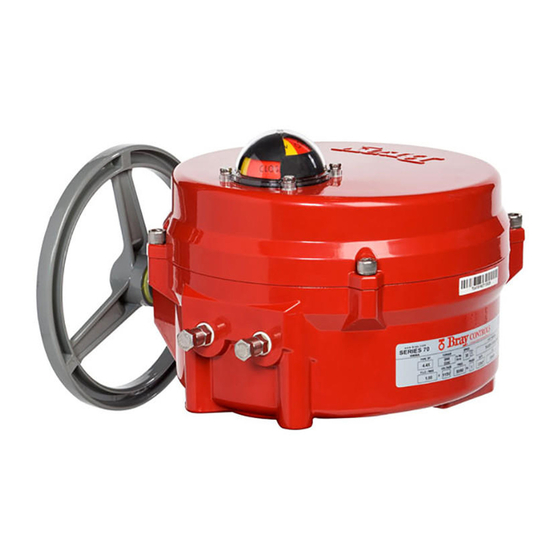
Bray 70 Series Operation And Maintenance Manual
24v on/off electric actuator
Hide thumbs
Also See for 70 Series:
- User manual ,
- Installation, operation and maintenance manual (48 pages) ,
- Operation and maintenance manual (30 pages)
Table of Contents
Advertisement
Advertisement
Table of Contents
Troubleshooting

Summary of Contents for Bray 70 Series
- Page 1 Series 70 24V On/Off Electric Actuator Operation and Maintenance Manual...
-
Page 2: Table Of Contents
B.1. Basic Tools ..........12 For information on this product and other Bray products please visit us at our web page - www.bray.com... -
Page 3: Definition Of Terms
Actuators are not weatherproof unless they are properly 1. The operation and maintenance of electrical equipment installed on the valve or prepared for storage. Bray will and systems in accordance with established safety not accept responsibility for deterioration caused on-site. -
Page 4: Operating Your Actuator
Figure 1. 5. MOUNTING THE ACTUATOR Yellow Stripe All Bray Series 70 electric actuators are suitable for direct mounting on Bray butterfly valves. With proper mounting hardware, the S70 actuator can be installed onto other quarter-turn valves or devices as well. -
Page 5: Commissioning
6. COMMISSIONING 6.2. Setting Travel Limit Switches Cams 6.1. Wiring Your Actuator Bray uses its patented cam design along with 2 SPDT mechanical switches to set the ‘Open’ and ‘Close’ position of the valve. The green cam actuates the ‘open’ switch when the actuator reaches the ‘open’... -
Page 6: Setting Mechanical Travel Stops
Bray Series 70 24V On/Off Electric Actuator Operations and Maintenance Manual 6.3. Setting Mechanical Travel Stops Follow the steps below to adjust the travel limit cams. 1. Remove the indicator rotor by pulling it away from the Mechanical travel stops are designed to prevent overtravel indicator shaft as shown in Figure 4. -
Page 7: Configuring Your 24V On/Off Controller
Bray Series 70 24V On/Off Electric Actuator Operations and Maintenance Manual 6.4 Configuring your 24V On/Off Controller 6.5 DIP Switch Setting Every Series 70 24V On/Off Actuator is fitted with a 24V The DIP switches on the 24V On/Off Controller are On/Off Controller as shown in Figure 7. -
Page 8: Field Or Factory Installable Options
7. FIELD OR FACTORY INSTALLABLE OPTIONS 7.1. Heater To prevent condensation from forming inside the actuator, Bray offers an optional heater as a field or a factory installable option. The heater is thermostatically controlled. It self-regulates by increasing or decreasing its electrical resistance relative to its temperature. -
Page 9: Control Station
Control Station can also be ordered with key lockable 7.5. Battery Backup Unit switches. To meet customer needs, Bray offers a Battery Backup Unit b. Control Station requires a dedicated set of auxiliary (BBU) for the 24 V Series 70 Electric Actuator. -
Page 10: Spinner
Rapid travel into a travel stop may also cause damage. 7.7. Receptacles (Quick Connectors) For quick and easy field wiring, Bray offers plug-in recep- tacles. Cordsets to fit these connectors can also be ordered in several lengths. -
Page 11: Troubleshooting Guide
Bray Series 70 24V On/Off Electric Actuator Operations and Maintenance Manual APPENDIX A A.1. Troubleshooting Guide The Series 70 24V On/Off actuator is easy to configure and operate, but if problems do occur, the following guide can assist in troubleshooting. -
Page 12: Troubleshooting Example
Bray Series 70 24V On/Off Electric Actuator Operations and Maintenance Manual A.3. Troubleshooting Example The following example demonstrates a typical troubleshooting process. Assume these starting conditions: 1. The handwheel is engaged (pulled away from the actuator). 2. The 24V On/Off Controller has been configured to enable torque switches but torque switches are not physically installed on the actuator. -
Page 13: Basic Tools
Bray Series 70 24V On/Off Electric Actuator Operations and Maintenance Manual APPENDIX B B.1. Basic Tools Common To All Units Terminal connections, cam adjustment Screwdriver, ⁄ " tip flat tip blade All switches, terminal strip, torque switch plate Screwdriver, No.1 Phillips Switchplate screws Screwdriver, No. - Page 14 Bray Series 70 24V On/Off Electric Actuator Operations and Maintenance Manual...
- Page 15 Bray Series 70 24V On/Off Electric Actuator Operations and Maintenance Manual...
- Page 16 Operations and Maintenance Manual Bray Controls All statements, technical information, and recommendations in this bulletin are for general use only. Consult Bray representatives or factory for the specific requirements and A Division of Bray International, Inc. material selection for your intended application. The right 13333 Westland East Blvd.


Need help?
Do you have a question about the 70 Series and is the answer not in the manual?
Questions and answers