Bray 70 Series Installation, Operation And Maintenance Manual
Servo nxt - ethernet/ip
Hide thumbs
Also See for 70 Series:
- User manual ,
- Installation, operation and maintenance manual (48 pages) ,
- Operation and maintenance manual (30 pages)

Related Manuals for Bray 70 Series


Summary of Contents for Bray 70 Series
- Page 1 SERIES 70 SERVO NXT - ETHERNET/IP Installation, Operation and Maintenance Manual BRAY.COM THE HIGH PERFORMANCE COMPANY...
- Page 2 FOR MORE INFORMATION ON THIS PRODUCT AND OTHER BRAY PRODUCTS PLEASE VISIT OUR WEBSITE – www.bray.com...
-
Page 3: Table Of Contents
Series 70 Servo NXT - EtherNet/IP Installation, Operation and Maintenance Manual Table of Contents 1.0 Safety Instructions - Definition of Terms ......3 2.0 Introduction. - Page 4 Series 70 Servo NXT - EtherNet/IP Installation, Operation and Maintenance Manual 4.5.3 Up Arrow Switch ........10 4.5.4 Down arrow Switch .
-
Page 5: Safety Instructions - Definition Of Terms
The primary function of the Servo NXT EIP is an EtherNet/IP adapter that provides complete to position the valve based on the feedback control and monitoring of the Bray S70 Electric position provided by a local potentiometer. The Valve Actuator. The basic function of the S70... -
Page 6: Operational Modes
Series 70 Servo NXT - EtherNet/IP Installation, Operation and Maintenance Manual 3.1 Operational Modes 3.1.4 Autocalibration Mode 3.1.1 Remote Mode The Servo NXT EIP uses an automated calibration sequence to determine the operating points By default, the operating mode of the Servo for the application in which it is installed. -
Page 7: Hardware Description
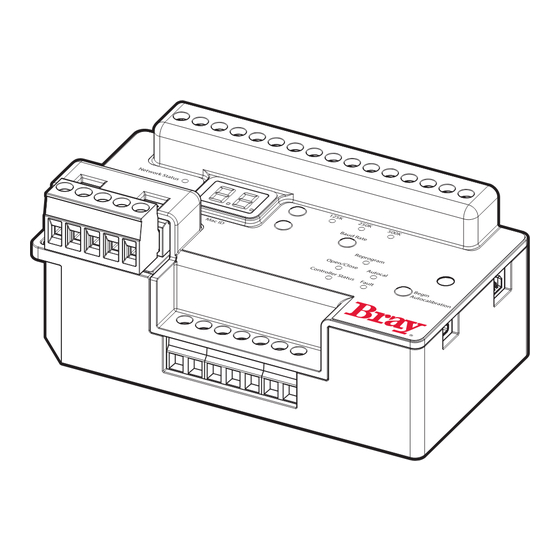
Bi-color (red / green) CIP Module Status Bi-color (red / green) CIP Network Status Bi-color (red / green) Position LED Red Status LEDs • Illuminate the Bray logo 1 = WHITE/ORANGE (+TX) Red Fault LEDs 2 = WHITE/GREEN (+RX) • Limit Switch fault 3 = ORANGE (-TX) •... -
Page 8: Power Connections
Series 70 Servo NXT - EtherNet/IP Installation, Operation and Maintenance Manual 4.2 Power Connections output gear of the actuator, and the cams on the cam shaft should be adjusted to ensure the 4.2.1 Input Power limit switches are engaged before any other mechanical limits are reached. -
Page 9: Control Box (Optional)
Series 70 Servo NXT - EtherNet/IP Installation, Operation and Maintenance Manual 4.3.4 Control Box (optional) 4.3.5 Potentiometer Connections for the local control station, if In addition to the limit switches, a potentiometer present. The local control station allows for local is also coupled to the cam shaft, this time by operation of the actuator, putting the Servo NXT a set of gears. -
Page 10: Led Description
Series 70 Servo NXT - EtherNet/IP Installation, Operation and Maintenance Manual 4.4 LED Description 4.4.1 Ethernet Link This yellow LED indicates the status of the Servo NXT EIP ethernet link. If it is on, then the link is good, and communication can occur. In addition, this LED also shows link activity. It blinks whenever an ethernet packet is transmitted or received. -
Page 11: Ethernet Speed
4.4.6 Product Status Autocalibration Mode, the unit will return to Remote Mode. These 2 red LEDs, illuminating the Bray logo, flash periodically to indicate the unit is powered 4.4.9 Manual Mode and operational. If these LEDs are not on, then This white LED is on when the unit is operating the unit likely does not have power applied. -
Page 12: Manual Mode Switch
This can be accomplished by uploading the EDS file for the Servo NXT EIP to the scanner, which can be found on the bray website, www.bray.com, or can be provided on request. 5.3 Address Assignment Every adapter added to an EtherNet/IP network must have an IP address. -
Page 13: Establish Connection
Series 70 Servo NXT - EtherNet/IP Installation, Operation and Maintenance Manual will automatically attempt to gain a lease for an maintain, or terminate a session. Once message available IP address. generation is started, it continues based on the RPI defined by the scanner, and it does not If the Servo NXT EIP is going to be connected require the presence of the scanner to occur. -
Page 14: Input Assembly Data
Series 70 Servo NXT - EtherNet/IP Installation, Operation and Maintenance Manual 5.4.1 Input Assembly Data Input Assembly Data Data Size Start Start Variable Notes Type (bits) Byte Feedback position from S70 potentiometer. Feedback Position REAL Range: 0-100% (0-90°) Current measured from the actuator motor Motor Current REAL Range: 0-5.0 A... - Page 15 Series 70 Servo NXT - EtherNet/IP Installation, Operation and Maintenance Manual Input Assembly Data Data Size Start Start Variable Notes Type (bits) Byte Open Limit Switch Set high if the open limit switch has been BOOL State reached Close Limit Switch Set high if the close limit switch has been BOOL State...
- Page 16 Series 70 Servo NXT - EtherNet/IP Installation, Operation and Maintenance Manual Input Assembly Data Data Size Start Start Variable Notes Type (bits) Byte Static Fault Handwheel Fault BOOL Set high when HW (handwheel) pulled Static Fault Feedback Fault BOOL Set high when outside allowed feedback pot range Static Fault Limit Switch Fault...
-
Page 17: Output Assembly Data
Series 70 Servo NXT - EtherNet/IP Installation, Operation and Maintenance Manual 5.4.2 Output Assembly Data Output Assembly Data Data Size Start Start Variable Notes Type (bits) Byte Customer position setpoint. Command Position REAL Range: 0-100% (0-90°) Toggle Bit Change bit state to start internal autocalibration routine. -
Page 18: Configuration Assembly Data
Series 70 Servo NXT - EtherNet/IP Installation, Operation and Maintenance Manual 5.4.3 Configuration Assembly Data Configuration Assembly Data Data Size Start Start Variable Notes Type (bits) Byte Position actuator operates to in the event of loss of Class 1 communication timeout. Failure Return Position REAL Range: 0-100% (0-90°) - Page 19 Series 70 Servo NXT - EtherNet/IP Installation, Operation and Maintenance Manual Configuration Assembly Data Data Size Start Start Variable Notes Type (bits) Byte Adjustable resolution range for input feedback position 0: 12-bit (Default) Feedback Resolution 1: 10-bit 2: 8-bit 3: 6-bit When high, inverts output command position Reverse Command BOOL...
-
Page 20: Quick Start Guide
Series 70 Servo NXT - EtherNet/IP Installation, Operation and Maintenance Manual 6.0 Quick Start Guide 1. Upload the EDS file for the Servo NXT EIP into the scanner that will be establishing the network connection. 2. Connect the Servo NXT EIP to the EtherNet/IP network through the M12 connector. -
Page 21: Technical Specifications
200 V Current Limit Switch Force 0.79 lbf [3.5 N] Temperature Rating -25 to 65°C Installation Designed for use within Bray actuators Electrical Input Voltage 120VAC ± 10% 230VAC ± 10% 24VAC ± 10% 24VAC ± 10% Motor Current, max... - Page 22 BRAY.COM All statements, technical information, and recommendations in this bulletin are for general use only. Consult Bray representatives or factory for the specific requirements and material selection for your intended application. The right to change or modify product design or product without prior notice is reserved.
Need help?
Do you have a question about the 70 Series and is the answer not in the manual?
Questions and answers