Table of Contents
Advertisement
Quick Links
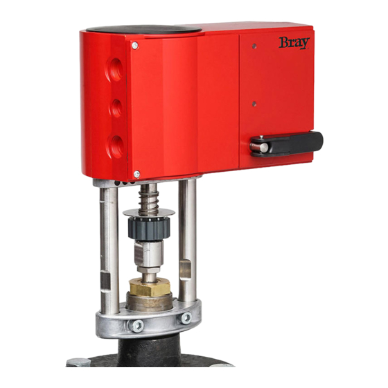
GAS -Spring Return Actuator - (GASRE24-450 & GASEX24-450)
24V, On/Off, Floating and Modulating
Automatic adaptation to valve, precision control and high energy efficiency with minimal operating noise.
Features
• Actuator with spring return action and pushing force of 450 lbs. (2000 N), in 'normally retracted' or 'normally extended' versions
• DC motor with electronic control unit and electronic load- dependent cut-off
• Automatic detection of control signal applied (modulating or floating), display via 2 LEDs
• The type of characteristic curve (linear, quadratic or equal percentage) can be adjusted in the drive
• Independent adaptation to valve stroke between 0.31 in.(8 mm) and 1.57 in.(40 mm), captive even if the power is turned off
• Direction of travel can be selected via screw terminals when making electrical connection or remotely
• Hand crank for external manual adjustment with motor cut-off and as trip for re-calibration
• Easy assembly with valve, spindle connection takes place automatically after application of control voltage
• Many adaptor kits allow assembly on third-party valves
Technical Description
• Two-part housing made of self-extinguishing red plastic and sealing to IP66 (equivalent to NEMA 4) protection class
• Maintenance-free gearbox in sintered steel, gearbox base-plate in steel
• Spring assembly in Stainless Steel
• Patented drive-valve coupling
• Mounting column made of stainless steel and mounting bracket for fitting valve made of cast light alloy
• Electrical connections 13 AWG (max. 2.5 mm²) with screw terminals
• Three knock-out cable entries for M20×1.5 (2×) and M16×1.5
• Fitting position: vertical to horizontal, but not upside down
Accessories
Auxillary Switches
0372333 001
Continuously adjustable, min. 100 mA and 12 V, additional load 6(2) A
0372333 002
Gold-plated contacts, from 1 mA and up to 30 V, further range 3(1) A
Adaptor kits for Industrial Globe Valves
GA-MTG-01
DG250-x and DG3-x
GA-MTG-02
DG4-x, DG5-x and DG6-x
Fittings
0386263 001
Screwed cable fitting M16 X 1.5
0386263 002
Screwed cable fitting M20 X 1.5
High Media Temperature Kit
0372336 240
Adaptor required for medium temperatures between 266˚F (130˚C) and 464˚F (240˚C)
Operation
After a new start, up to 45 s of waiting time will pass before the drive is available again. Depending on the type of connection
(see the wiring diagram), the device can be used as a modulating drive (0...10 V and/or 4...20 mA), a On/Off (2-point) drive
(extend/retract) or a Floating (3-point) drive (extend/stop/retract). The run time of the drive can be set according to the specific
requirements, using switches S1 and S2. Switches S3 and S4 are used to configure the characteristic curve (equal percentage,
linear or quadratic). The external hand crank allows you to adjust the position manually. When the hand crank is folded out, the
motor is switched off. After the hand crank is folded back, the spring function is active again and the setpoint position is adopted
again (without calibration). If the hand crank is unfolded, the drive stays in this position.
Calibration and feedback signal
The drive calibrates itself automatically, whether it is used in a modulating, On/Off (2-point )or Floating (3-point) mode. Voltage
needs to be applied to terminal 21. As soon as voltage is applied to either terminals 2a or 2b for the first time and the waiting
period (both LEDs green) of approximately 45 seconds has elapsed, the drive moves to the lower limit stop on the valve, thus
enabling automatic connection with the valve spindle. Then it moves to the upper limit stop, and the value is recorded and saved
with the help of a path measurement system.
GAS Series -
Actuator
—
Operating Instructions
1
Bray Controls Commercial Division
13788 West Road, Suite 200A
Houston, Texas 77041
BCDSales@Bray.com
Phone: 1-888-412-2729
Fax: 1-888-412-2720
www.braycommercialdivision.com
1/28/19
Advertisement
Table of Contents

Related Manuals for Bray GAS Series


Summary of Contents for Bray GAS Series
- Page 1 Bray Controls Commercial Division 13788 West Road, Suite 200A Houston, Texas 77041 BCDSales@Bray.com Phone: 1-888-412-2729 Fax: 1-888-412-2720 www.braycommercialdivision.com GAS Series - — 1/28/19 Actuator Operating Instructions GAS -Spring Return Actuator - (GASRE24-450 & GASEX24-450) 24V, On/Off, Floating and Modulating Automatic adaptation to valve, precision control and high energy efficiency with minimal operating noise.
- Page 2 GAS Series - — Actuators Operating Instructions Continued Calibration and feedback signal - Continued The control signal and the feedback signal are adjusted to this effective stroke. After an interruption to the voltage or a spring return action, no re-calibration is performed and the values are saved. Calibration must be performed in order to utilize the feedback signal when On/Off (2-point) or Floating (3-point) control is required.
- Page 3 GAS Series - — Actuators Operating Instructions Continued Modulating Actuator (0...10 V and/or 4...20 mA) - Continued The coding switch can be used to set the characteristic for the valve. Equal-percentage and square characteristics can only be produced if the device is used as a proportional-action drive. Further switches can be used to select the run-times (can be used for the On/Off (2-point), Floating (3-point) or proportional functions).
- Page 4 GAS Series - — Actuators Operating Instructions Continued - Curve Characteristic Switch Settings Desired Characteristic Characteristic Switch Coding Effective on Valve Character. Curve for Drive Curve for Valve Curve Stroke 1 2 3 Signal Stroke Signal Stroke 1 2 3...
- Page 5 GAS Series - — Actuators Operating Instructions Continued - Dimensions 2.87 in. 0.73 in. 2.24 in. Spring Return (18.5mm) (57mm) (73mm) 9.06 in.(230mm) Adaptor for media temperatures between 266˚F (130˚C) and 464˚F (240˚C) 3.54 in.(90mm) Description Part Number 2.52 in.
- Page 6 Disclaimer - The performance specifications are nominal and conform to acceptable industry standards. For application at conditions beyond these specifications, consult the local Bray office. Bray, Inc. shall not be liable for damages resulting from misapplication or misuse of its products.
Need help?
Do you have a question about the GAS Series and is the answer not in the manual?
Questions and answers