Bray 70 Series Operation And Maintenance Manual
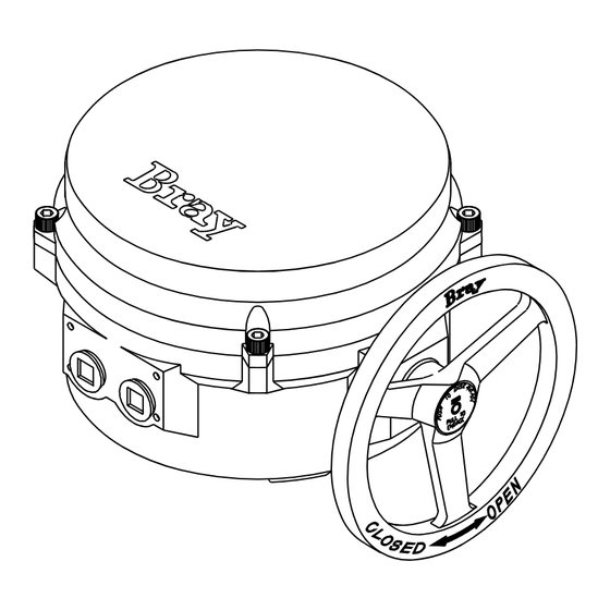
Tunnel damper model electric actuator
Hide thumbs
Also See for 70 Series:
- User manual ,
- Installation, operation and maintenance manual (48 pages) ,
- Operation and maintenance manual (30 pages)
Table of Contents
Advertisement
Quick Links
Advertisement
Table of Contents

Subscribe to Our Youtube Channel
Related Manuals for Bray 70 Series


Summary of Contents for Bray 70 Series
- Page 1 SERIES 70 TUNNEL DAMPER MODEL ELECTRIC ACTUATOR OPERATION AND MAINTENANCE MANUAL...
-
Page 3: Table Of Contents
12 ............10 exploded view and partS liSt of houSing Size 30 ............11 exploded view and partS liSt of houSing Size for information on thiS product and other bray productS - www.bray.com pleaSe viSit uS at our web page... - Page 4 BRAY Series 70 Tunnel Damper Electric Actuator Operation and Maintenance Manual afeTy nsTruCTiOns efiniTiOn Of erms read and fOllOW THese insTruCTiOns saVe THese insTruCTiOns indicates a potentially hazardous situation which, if not avoided, could result WARNING in death or serious injury.
-
Page 5: Principle Of Operation
BRAY Series 70 Tunnel Damper Electric Actuator Operation and Maintenance Manual W - DESIGNATES THE SPEED uMbering ysteM eference chart 15/18 seconds eries Orque Peed rOduct tyle Oltage X - DESIGNATES STYLE Basic Unit - Declutchable , ¼ t Ousing... -
Page 6: Manual Override Operation
Actuators are not weatherproof until properly installed Install the furnished mounting studs by threading on the valve or prepared for storage. Bray cannot accept them all the way into the actuator base. responsibility for deterioration caused on-site once the Fasten in place with the furnished hex nuts and lock cover is removed. - Page 7 BRAY Series 70 Tunnel Damper Electric Actuator Operation and Maintenance Manual NOTICE Striker Bar The conduit connections must be properly sealed to maintain the weatherproof integrity of the actuator enclosure. CAUTION Do not reverse motor instantaneously when it is still running.
- Page 8 To prevent condensation from forming inside the actuator, Bray offers a heater as standard in Series 70 Tunnel Damper models. The heater is a PTC (Positive Temperature Coefficient) style which has a unique temperature - resistance characteristic. The heater self- regulates by increasing its electrical resistance relative to its temperature.
-
Page 9: Field Wiring
Wiring diagram for CCW Open Unit with form-ZZ (DPDT-DB) travel switches (Drawn for actuator in its fully closed [CW] condition) Note: Bray Series 70 Tunnel Damper electric actuator wiring is the same, regardless of CW or CWW application. Control is achieved through field wiring. - Page 10 BRAY Series 70 Tunnel Damper Electric Actuator Operation and Maintenance Manual isassembly and ssembly To remove the Gearmotor, first disconnect the mo- tor leads which run to the capacitor, and unscrew OOls required the mounting screws (four lower, one upper). The motor can now be removed vertically out of the unit.
- Page 11 BRAY Series 70 Tunnel Damper Electric Actuator Operation and Maintenance Manual PPendix asic OOls OMMOn nits Terminal connections, cam adjustment Screwdriver, 1/4” tip flat tip blade All switches, terminal strip, torque switch plate Screwdriver, No.1 phillips Switchplate screws, capacitor Screwdriver, No.2 phillips...
-
Page 12: 19 Heater
BRAY Series 70 Tunnel Damper Electric Actuator Operation and Maintenance Manual 70 t eries unnel aMPer Odel Ousing ON / OFF 1 COVER PLATE WITH STUD 38 WORM SHAFT 2 OIL RESISTANT GASKET 39 OVERRIDE DRIVE PIN 3 COVER FASTENING SCREW... - Page 13 BRAY Series 70 Tunnel Damper Electric Actuator Operation and Maintenance Manual 70 t eries unnel aMPer Odel Ousing ON / OFF 1 COVER FASTENING SCREW 38 O RING-S-126 2 COVER 39 O RING-S118 3 O-RING 40 RETAINING RING.INTERNAL 4 CAM ASSEMBLY...
- Page 14 BRAY Series 70 Tunnel Damper Electric Actuator Operation and Maintenance Manual...
- Page 15 BRAY Series 70 Tunnel Damper Electric Actuator Operation and Maintenance Manual...
- Page 16 CONTROLS A Division of BRAY INTERNATIONAL, Inc. 13333 Westland East Blvd. Houston, Texas 77041 281-894-5454 FAX 281/894-9499 www.bray.com Bray is a registered trademark of BRAY INTERNATIONAL, Inc. ® © 2014 Bray International. All rights reserved. OM-70TD-001 07-2014...
Need help?
Do you have a question about the 70 Series and is the answer not in the manual?
Questions and answers