Bray Series 70 Operation And Maintenance Manual
2nd generation electric actuator
Hide thumbs
Also See for Series 70:
- User manual ,
- Installation, operation and maintenance manual (48 pages) ,
- Operation and maintenance manual (30 pages)

Related Manuals for Bray Series 70


Summary of Contents for Bray Series 70
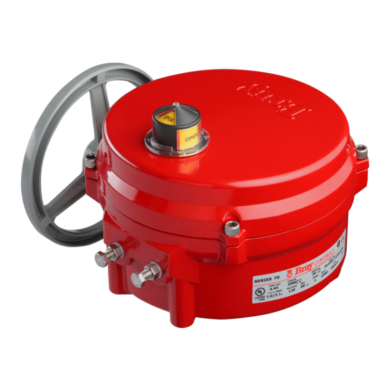
- Page 1 Your Global Flow Control Partner ™ Series 70 2nd Generation Electric Actuator Operation and Maintenance Manual...
-
Page 3: Table Of Contents
Series 70 - Housing Size 180 for 3:1 Gear Box . . . . . . . . . . . . . . . -
Page 4: Safety Instructions - Definition Of Terms
Series 70 Electric Actuator Operation and Maintenance Manual Safety Instructions - Definition of Terms READ AND FOLLOW THESE INSTRUCTIONS SAVE THESE INSTRUCTIONS indicates a potentially hazardous situation which, if not avoided, could WARNING result in death or serious injury. indicates a potentially hazardous situation which, if not avoided, may result CAUTION in minor or moderate injury. -
Page 5: Part Numbering System Reference Chart
. Torque switches installed by The Bray Series 70 is a quarter turn electric actuator Bray are factory adjusted to the output torque rating with manual override for use on any quarter turn valve of the unit using electronic torque testing equipment . -
Page 6: Manual Override Operation (Declutchable)
Actuators are not weatherproof until properly installed 4 . Install the furnished mounting studs by threading on the valve or prepared for storage . Bray cannot accept them all the way into the actuator base . responsibility for deterioration caused on-site once the cover is removed . -
Page 7: Multiple Actuator (Parallel) Wiring
Series 70 Electric Actuator Operation and Maintenance Manual NOTICE CAUTION The conduit connections must be properly sealed to Do not reverse motor instantaneously when it is still maintain the weatherproof integrity of the actuator running. Reversing direction to actuator motor when enclosure. -
Page 8: Close Travel Switch Adjustment
Series 70 Electric Actuator Operation and Maintenance Manual Close Travel Switch Adjustment 5 . With the travel switch in the closed position, rotate the handwheel clockwise ½ turn for Housing Size 6, 1 turn for Housing Size 12, ½ turn for Housing Size 30, and 2 turns for Housing Size180 . -
Page 9: Disassembly And Assembly
Series 70 Electric Actuator Operation and Maintenance Manual Disassembly and Assembly 3 . The switchplate can be independently disassembled . 4 . To remove the Gearmotor, first disconnect the motor Tools required: leads which run to the capacitor, and unscrew the See Appendix A for a complete list of basic tools . -
Page 10: Field Or Factory Installable Options
Field or Factory Installable Options Torque Switches Torque switches are a factory installed and calibrated option available for all Series 70 units . Installation is simple, but due to the requirement for special calibration equipment, it is not recommended for field installation . -
Page 11: Heater
To prevent condensation from forming inside the until approx . 1/2 to 1” is left above the bracket as actuator, Bray offers an optional heater . The heater is shown in diagram . a PTC (Positive Temperature Coefficient) style which has a unique temperature - resistance characteristic . -
Page 12: Installation Procedure
• Disconnect all power to the unit . The calibration procedure defines the limits of operation of the Series 70 Actuator between the fully open valve • Remove the on/off duty, 9 point terminal strip and position and the fully closed valve position . The cams its marker . -
Page 13: External Signal Feedback Potentiometer
Series 70 Electric Actuator Operation and Maintenance Manual External Signal Feedback Set the Potentiometer Potentiometer 1 . Manually operate the actuator handwheel until the unit is in the fully closed position . Potentiometers for external feedback can be field installed on all continuous duty actuators . Actuators 2 . -
Page 14: Auxiliary Switch Configuration Chart
Series 70 Electric Actuator Operation and Maintenance Manual Auxiliary Switch Configuration Chart CONFIGURATION HOUSING HOUSING HOUSING SIZE 6 SIZES 12 & 30 SIZE 180 1. ON/OFF (Intermittent Duty 2 Switch 2 Switch Motor) with Main Switch- 2 Cams 2 Cams... -
Page 15: Typical Wiring Diagram: On/Off Service
Series 70 Electric Actuator Operation and Maintenance Manual Typical Wiring Diagram: On/Off Service Wiring diagram for basic unit with Form-C (SPDT) travel limit switches, I .R .B ., and double override switches . (Drawn for actuator in its fully closed condition .) Wiring diagram for unit with Form-C (SPDT) travel limit switches, “Voltage Free”... -
Page 16: Typical Wiring Diagram: Modulating Service
Series 70 Electric Actuator Operation and Maintenance Manual Typical Wiring Diagram: Modulating Service Wiring diagram for unit with Form-C (SPDT) travel limit switches, “Voltage Free” Auxiliary open/close switches, Servo and double override switches . (Drawn for actuator in its full closed position .) Warning: Turn ALL Power Off prior to adjusting DIP switches. -
Page 17: Adjustments, Calibration And Status Led Of Servo Pro
Series 70 Electric Actuator Operation and Maintenance Manual Adjustments, Calibration and Status LED of Servo Pro A. Adjust the open and close speed of your B. Calibrate the Servo: actuator (The fastest closing speed of your 1 . Manually position your actuator somewhere in mid actuator is printed on the label of the unit): position;... -
Page 18: Receptacles (Quick Connectors)
3 . Wiring diagram (SK-# below) shielded . Wiring diagrams for plug-in receptacles for either the Bray Series 70 or the local control station will Tools required: be provided as a separate diagram . Units ordered with •... -
Page 19: Spinner
A spinner is available to ease and speed the manual blocks internally, the correct part number must be used override of the Bray Series 70 actuator . The Housing Size 6 to ensure you order the correct unit (see price sheet). -
Page 20: Basic Tools
Series 70 Electric Actuator Operation and Maintenance Manual Appendix A Basic Tools Common To All Units Terminal connections, cam adjustment Screwdriver, ⁄ " tip flat tip blade All switches, terminal strip, torque switch plate Screwdriver, No .1 Phillips Switchplate screws, capacitor Screwdriver, No . -
Page 21: Actuator Troubleshooting Chart
Series 70 Electric Actuator Operation and Maintenance Manual Appendix B Actuator Troubleshooting Chart Problem Possible Cause Solutions Override is engaged Push handwheel in all the way Wiring is incorrect Check wiring and power supply Actuator does not operate Actuator motor has reached its... -
Page 22: S70 Servo Pro Troubleshooting Chart
Series 70 Electric Actuator Operation and Maintenance Manual S70 Servo Pro Troubleshooting Chart Refer to the Servo Pro Operation Manual for more information . Problem Possible Cause Solutions Signal is fluctuating beyond Increase the deadband using the Actuator moves back and deadband setting Deadband trim pot . -
Page 23: Appendix C - Exploded Views
Series 70 Electric Actuator Operation and Maintenance Manual Appendix C - Exploded Views Series 70 - Housing Size 6 ON / OFF 1 Position Indicator Cover 38 Manual Override Shaft 2 Position Indicator Seal 39 Manual Override Sleeve 3 Cover Fastening Screws... -
Page 24: Series 70 - Housing Size 12
Series 70 Electric Actuator Operation and Maintenance Manual Series 70 - Housing Size 12 ON / OFF 1 Position Indicator Cover 37 O-Ring 2 Position Indicator Seal 38 O-Ring 3 Cover Fastening Screw 39 Retaining Ring 4 Cover 40 Handwheel Warning Label... -
Page 25: Series 70 - Housing Size 30
Series 70 Electric Actuator Operation and Maintenance Manual Series 70 - Housing Size 30 ON / OFF 1 Position Indicator Cover 37 O-Ring 2 Position Indicator Seal 38 O-Ring 3 Cover Fastening Screw 39 Retaining Ring, Internal 4 Cover 40 Spring Pin... -
Page 26: Series 70 - Housing Size 180 For 3:1 Gear Box
38 39 40 Series 70 Electric Actuator Operation and Maintenance Manual Series 70 - Housing Size 180 for 3:1 Gear Box ON / OFF 1 Cover Fastening Screw 34 Handwheel Warning Label 2 Cover 35 Handwheel 3 O-Ring 36 Spring Pin... -
Page 27: Series 70 - 3:1 Gear Box
Series 70 Electric Actuator Operation and Maintenance Manual Series 70 - 3:1 Gear Box ON / OFF 1 Fastening Screw 2 Position Indicator Plate 3 Position Indicator Gasket 4 Actuator/Gear Box Gasket 5 Dowel Pin 6 O-Ring 7 Washer, Flat, Nylon... - Page 28 . The right to change or modify product design or product without prior notice is reserved . Patents issued and applied for worldwide . is a registered trademark of Bray International, Inc . | © 2016 Bray International, Inc . All rights reserved . | OM-70-001 Bray ®...
Need help?
Do you have a question about the Series 70 and is the answer not in the manual?
Questions and answers