Table of Contents
Advertisement
Quick Links
INSTRUCTION MANUAL
RECHARGEABLE LI-ION BATTERY SYSTEM
SKU
DESCRIPTION
12259
RECHARGEABLE LI-ON BATTERY MODULE 51.2V 206AH -RACKABLE
12260
RACKS FOR 10PCS BATTERIES AND 1PC BMS
12261
HIGH VOLTAGE BATTERY CLUSTER CONTROL BOX WITH COM AND POWER CABLES
Thank you for selecting and buying V-TAC Product. V-TAC will serve you the best. Please
read these instructions carefully & keep this user manual handy for future reference. If you
have any another query, please contact our dealer or local vendor from whom you have
purchased the product. They are trained and ready to serve you at the best.
MULTI-LANGUAGE
MANUAL QR CODE
Please scan the QR code
to access the manual in
multiple languages.
In case of any query/issue with the product, please reach out to us at: support@v-tac.eu
For More products range, inquiry please contact our distributor or nearest dealers.
V-TAC EUROPE LTD. Bulgaria, Plovdiv 4000, bul.L.Karavelow 9B
INTRODUCTION
1
WEEE Number: 80133970
Advertisement
Table of Contents

Related Manuals for V-TAC OHR-10.5K


Summary of Contents for V-TAC OHR-10.5K
- Page 1 HIGH VOLTAGE BATTERY CLUSTER CONTROL BOX WITH COM AND POWER CABLES INTRODUCTION Thank you for selecting and buying V-TAC Product. V-TAC will serve you the best. Please read these instructions carefully & keep this user manual handy for future reference. If you have any another query, please contact our dealer or local vendor from whom you have purchased the product.
-
Page 2: Table Of Contents
CONTENT 1 .Important information in the manual ..................3 1.1 Scope ........................... 3 1.2 Description of OHR-206 ......................3 1.3 Meaning of Symbols ......................4 1.4 General Safety Information ....................6 1.5 Disclaimer ..........................6 1.6 Installation environment ....................... 6 1.7 Requirements for Installation Personnel ................ - Page 3 5.2 User login ........................... 29 5.3 Detail ..........................30 5.3 Alarm Setup........................31 5.4 Alarm ..........................32 5.5 Data Log ..........................32 5.6 Connection ......................... 33 6 Battery Module Storage ......................34 7 Maintenance ..........................35 IMPORTANT NOTES This product contains battery type "Secondary" (rechargeable). •...
-
Page 4: Important Information In The Manual
1.Important information in the manual 1.1 Scope The installation and operation manual applies to the modular battery energy storage system. Please carefully read this installation and operation manual to ensure the safe installation, preliminary debugging, and maintenance of OHR-206. Installation, preliminary debugging, and maintenance must be carried out by qualified and authorized personnel. -
Page 5: Meaning Of Symbols
1.3 Meaning of Symbols This manual contains the following types of warnings: Danger! It may cause an electric shock. Even when the equipment is disconnected from the power grid, the voltage-free state will have a time lag. Danger! If the instructions are not observed, death or severe injury may occur. - Page 6 Attention! The risk of explosion Incorrect operation or fire may cause the lithium-ion battery unit to ignite or explode, leading to serious injury. • Do not install or operate the battery module in explosive or high-humidity areas. • Store the battery module in a dry place within the temperature range specified in the data sheet.
-
Page 7: General Safety Information
If there are any questions, please contact V-TAC after service. 1.5 Disclaimer V-TAC Europe Ltd shall not be liable for personal injury, property loss, product damage and subsequent losses under the following circumstances. • Failure to comply with the provisions of this manual. - Page 8 • When installing the battery energy storage system, ensure that it stands on a sufficiently dry and flat surface with sufficient bearing capacity. Without the manufacturer’s written approval, the installation site’s altitude shall not be higher than 2,000 meters. The output power of the battery decreases with the altitude.
-
Page 9: Requirements For Installation Personnel
1.7 Requirements for Installation Personnel All work shall comply with local applicable regulations and standards. The installation of OHR-206 can only be completed by electricians with the following qualifications: • Trained in dealing with hazards and risks associated with the installation and operation of electrical equipment, systems, and batteries. -
Page 10: Safety
2. Safety 2.1 Safety rules To avoid property damage and personal injury, the following rules shall be followed when working on the hazardous live parts of the battery energy storage system: • It is available for use. • Ensure that it will not restart. •... -
Page 11: Permissible And Impermissible Storage Positions Of A Packaged Battery Module
The battery energy storage system can be damaged, if not properly transported. The battery module can only be transported vertically. Note that these parts may be top-heavy.Failure to follow this instruction may result in damage to the part. During transportation, the battery storage rack may be damaged when it is installed with the battery module. -
Page 12: Description And Installation Of Ohr-206 Battery
4. Description and installation of OHR-206 battery 4.1 Installation Precautions WARNING! Possible damage to the building due to static overload 1. The total weight of the battery storage system is kgs. Ensure that the installation site has sufficient bearing capacity. 2. - Page 13 1029±2 Weight (Kg) Recommend Charge/Discharge Current (A) Communicaiton Ingress Protection IP20 Altitude ≤2000m Cycle Life 25±2°C,0.5C/0.5C,EOL70%≥6000 System voltage,Current,cell voltage,cell Monitoring Parameters temperature,module temperature Intelligent algorithm Working Temperature 0 ℃ ~55 ℃ Charge -20 ℃ ~55 ℃ Discharge Storage Temperature 0~35 ℃...
-
Page 14: Preparation
4.4. Preparation 4.4.1 Tools required ① PHILIP2# crosshead screwdriver; ② 10mm hexagon socket ③ 24mm wrench 4.4.2 OHR-5.5U-HRACK-12 Parts description... -
Page 15: Installation Of Rack
Installation of Rack 4.4.3 1. **Step 1:** First, lay Side Beam L (a) flat on a horizontal surface. Install the six L Support Crossbeams one by one from left to right onto Side Beam L (pay attention to the installation direction). -
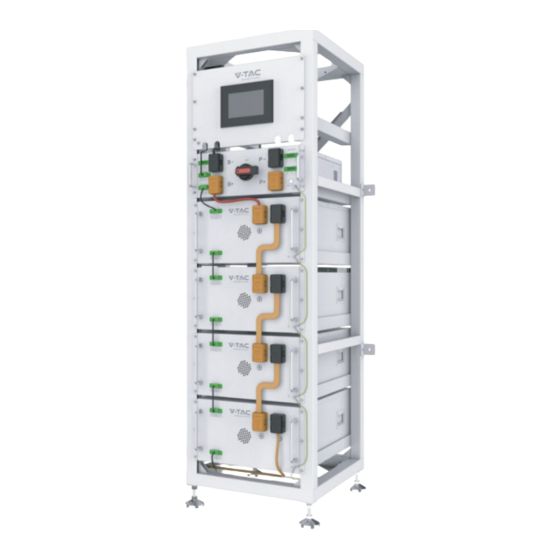
Page 21: Description Of Battery Module
Description of Battery Module Name Description. Position Connection position of battery module Front ① communication supply input or output. Connection position of battery module Front ② communicationand power supply input or output. Battery module positive pole (orange) Front ③ Battery module negative pole (black). Front ④... -
Page 22: Description Of High-Voltage Bms Box
Description of high-voltage BMS box Name Description. Position Inverter communication port Front ① Communication connection between high Front ② voltage BMS box and LCD screen Communication port between battery and Front ③ high-voltage BMS box 220V AC input port (reserved) Front ④... -
Page 23: Description Of Battery Module In Rack
Description of Battery Module in Rack... -
Page 25: Installation Of The Battery Module To The Rack
Installation of the Battery Module to the Rack Insufficient or no grounding may cause an electric shock. Device malfunctions, and insufficient or no grounding may cause device damage and life-threatening electric shocks. Note: Before installing the battery, please turn the manual switch of the high-voltage control box to the off position. - Page 27 Connecting LCD screen...
-
Page 28: Battery Cluster Connected To Inverter
4.9 Battery cluster connected to inverter... -
Page 29: System Startup And Shutdown
4.10 System startup and shutdown 4.10.1 Startup procedure ① After connecting the battery cable, press the BMS start button and wait for the screen to light up.. ② When the battery pack makes two clicks and the relay ON the display is closed, turn the circuit breaker to ON. -
Page 30: Ohr's User Interface
5 OHR’S User Interface 5.1 Main Interface 5.2 User login Account: Admin Password:123... -
Page 31: Detail
5.3 Detail... -
Page 32: Alarm Setup
5.3 Alarm Setup... -
Page 33: Alarm
5.4 Alarm 5.5 Data Log... -
Page 34: Connection
5.6 Connection This function is not required for single cluster battery... -
Page 35: Battery Module Storage
6 Battery Module Storage ①To ensure the battery service life, the storage temperature shall be kept between 0°C~35°C. ②The battery shall be cycled at least once every 6 months. ③To minimize self-discharge in a long storage period, disconnect the battery connection (1/2) of the high-voltage control box of the DC connecting cable. -
Page 36: Maintenance
7 Maintenance Warning! Improper decommissioning may cause damage to the equipment and/or battery inverter. Before maintenance, ensure that OHR-206 is decommissioned according to relevant provisions. Note: All maintenance work shall comply with local applicable regulations and standards. The USB-CAN port of OHR has the functions of upgrading firmware and recording battery data, which can be used as an auxiliary tool. -
Page 37: Legal Statement
Do not dispose of batteries as household waste! Legal Statement The information contained in the document is the property of V-TAC Europe Ltd. All information shall not be published in whole or in part without the written permission of V-TAC Europe Ltd.
Need help?
Do you have a question about the OHR-10.5K and is the answer not in the manual?
Questions and answers