Table of Contents
Advertisement
Quick Links
INSTRUCTION MANUAL
Thank you for selecting and buying V-TAC Product. V-TAC will serve you the best. Please
read these instructions carefully & keep this user manual handy for future reference. If you
have any another query, please contact our dealer or local vendor from whom you have
purchased the product. They are trained and ready to serve you at the best.
MULTI-LANGUAGE
MANUAL QR CODE
Please scan the QR code
to access the manual in
multiple languages.
In case of any query/issue with the product, please reach out to us at: support@v-tac.eu
For More products range, inquiry please contact our distributor or nearest dealers.
V-TAC EUROPE LTD. Bulgaria, Plovdiv 4000, bul.L.Karavelow 9B
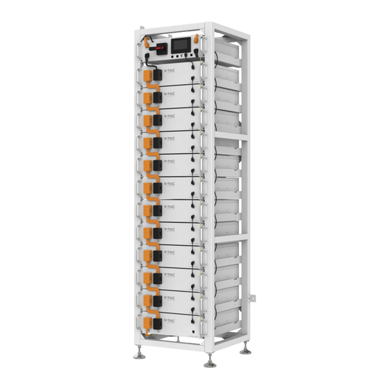
OHR-100 RECHARGEABLE
LI-ION BATTERY SYSTEM
INTRODUCTION
SKU
DESCRIPTION
12239 Rechargeable Li-ion Battery Module
12238 High Voltage Battery Cluster Control Box
12219 Standard 5-meter Positive power cable
12220 Standard 5-meter Negative power cable
12218 Racks for 12pcs Batteries and 1PC BMS
1
WEEE Number: 80133970
Advertisement
Table of Contents

Related Manuals for V-TAC OHR-100


Summary of Contents for V-TAC OHR-100
- Page 1 12218 Racks for 12pcs Batteries and 1PC BMS INTRODUCTION Thank you for selecting and buying V-TAC Product. V-TAC will serve you the best. Please read these instructions carefully & keep this user manual handy for future reference. If you have any another query, please contact our dealer or local vendor from whom you have purchased the product.
-
Page 2: Table Of Contents
3. Transport to the end customers..................9 3.1 Provisions on Shipping of Battery Modules:............9 3.2 Permissible and Impermissible Storage Positions of a Packaged Battery Module10 4. Description and installation of OHR-100 battery ............11 4.1 Installation Precautions..................11 4.2 OHR-100 Product Description ................11 4.3 Technical Data ....................... - Page 3 5.6.3 Diagnostic Information ................32 5.6.4 Cumulative Time Information ..............32 5.7 Set Up ........................ 33 6 Xiaodan Energy Sto rage App ................34 6.1. App download ....................34 6.1.1 Android version ..................34 6.1.2 iOS version ......................34 6.2. Log in and register ....................35 6.2.1 Log in ......................
-
Page 4: Important Information In The Manual
The installation and operation manual applies to the modular battery energy storage system. Please carefully read this installation and operation manual to ensure the safe installation, preliminary debugging, and maintenance of OHR-100. Installation, preliminary debugging, and maintenance must be carried out by qualified and authorized personnel. Please keep this... -
Page 5: Meaning Of Symbols
1.3 Meaning of Symbols This manual contains the following types of warnings: Danger! It may cause an electric shock. Even when the equipment is disconnected from the power grid, the voltage-free state will have a time lag. Danger! If the instructions are not observed, death or severe injury may occur. - Page 6 Attention! The risk of explosion Incorrect operation or fire may cause the lithium-ion battery unit to ignite or explode, leading to serious injury. • Do not install or operate the battery module in explosive or high-humidity areas. • Store the battery module in a dry place within the temperature range specified in the data sheet.
-
Page 7: General Safety Information
Danger! Failure to comply with the safety information can lead to life-threatening situations. 1. Improper use can cause death. Operators of OHR-100 must read this manual and observe all safety information. 2. Operators of OHR-100 must comply with the specifications in this manual. - Page 8 Compliance with the specifications in this manual is also part of proper use. The use of the OHR-100 system is prohibited in the following circumstances: • Mobile use on land or in the air (use on water only with the manufacturer's consent and with the manufacturer's written consent).
-
Page 9: Requirements For Installation Personnel
All work shall comply with local applicable regulations and standards. The installation of OHR-100 can only be completed by electricians with the following qualifications: • Trained in dealing with hazards and risks associated with the installation and operation of electrical equipment, systems, and batteries. -
Page 10: Safety
2. Safety 2.1 Safety rules To avoid property damage and personal injury, the following rules shall be followed when working on the hazardous live parts of the battery energy storage system: • It is available for use. • Ensure that it will not restart. •... -
Page 11: Permissible And Impermissible Storage Positions Of A Packaged Battery Module10
The maximum weight of a single rack of OHR-100 can reach 640kg. We suggest that at least 2-3 people work together to install the battery rack. The lifting device is helpful for heavy parts, and the pulley or cart for light parts. -
Page 12: Description And Installation Of Ohr-100 Battery
2. When selecting the installation site, consider the transportation route and necessary site cleanup. 4.2 OHR-100 Product Description OHR-100 is a high-voltage lithium-ion battery system. It provides a reliable backup power supply for supermarkets, banks, schools, farms and small factories to smooth the load curve and achieve peak load transfer. -
Page 14: Preparation
4.4. Preparation 4.4.1 Tools required ① PHILIP2# crosshead screwdriver; ② 10mm hexagon socket ③ 24mm wrench 4.4.2 OHR-3U-HRACK Parts description... -
Page 15: Installation Of Rack
Installation of Rack 4.4.3 ①Take out two side beams and four Connect sorghums, connect the four Connect sorghums to the side beams, and then fix the side beams and Connect sorghums with screws. After fixing, take out eight Transverse connectors and connect them to the side beams, and fix the side beams and Transverse connectors with screws ②The left and right diagonal braces are fixed on both sides of the beam with round head hexagon combination screws and hexagon wrenches. -
Page 18: Description Of Battery Module
Description of Battery Module Name Description. Position Battery module positive pole (orange) Front ① Connection position of battery module Front ② communication and power supply output. Battery module negative pole (black). Front ③ Connection position of battery module Front ④ communication supply input. -
Page 19: Description Of High-Voltage Bms Box
Description of high-voltage BMS box Name Description. Position High voltage BMS box module negative pole (black). Front ① High voltage BMS box module positive pole (orange) Front ② Used to manually control the connection between the DC circuit breaker Front ③... -
Page 20: Description Of Battery Module In Rack
Description of Battery Module in Rack... -
Page 22: Installation Of The Battery Module To The Rack
Installation of the Battery Module to the Rack Insufficient or no grounding may cause an electric shock. Device malfunctions, and insufficient or no grounding may cause device damage and life-threatening electric shocks. Note: Before installing the battery, please turn the manual switch of the high-voltage control box to the off position. -
Page 25: Battery Cluster Connected To Inverter
4.9 Battery cluster connected to inverter... -
Page 28: System Startup And Shutdown
4.10 System startup and shutdown Startup procedure ① After connecting the battery cables, press the DC circuit breaker on the high-voltage BMS box to turn OFF to ON. ② Press the start button and wait for the screen to light up. ③Turn on the circuit breaker after the battery pack is started. -
Page 29: Ohr's User Interface
5 OHR’S User Interface 5.1 Main Interface Fault display area 5.2 Cell Voltage... -
Page 30: Cell Temperature
5.3 Cell Temperature 5.4 Heating Temperature... -
Page 31: Relay Status
5.5 Relay Status 5.6 Other... -
Page 32: Heating Information
5.6.1 Heating Information 5.6.2 Insulation Resistense... -
Page 33: Diagnostic Information
5.6.3 Diagnostic Information 5.6.4 Cumulative Time Information... -
Page 34: Set Up
5.7 Set Up... -
Page 35: Xiaodan Energy Storage App
6 Xiaodan Energy Storage App 6.1. App download 6.1.1 Android version Enter the official website of Youdan Technology https://www.udantech.com/#/ , click on the "SAAS Application" column in the top navigation bar, pull down to the mobile app application module, and you can see the mobile WeChat Mini Program and App application download. -
Page 36: Log In And Register
6.2. Log in and register 6.2.1 Log in After opening the APP, enter the login interface to log in with your account. • Currently supports logging in through email accounts •... -
Page 37: Register
6.2.2 Register At the bottom of the login page, click the "Account Registration" button to enter • the registration process. -
Page 38: Experience Login
Currently, you can register with an email account. After registration, you need to • go through the device verification process and enter the device SN code or device QR code for identification. 6.2.3 Experience login At the bottom of the login page, click the "Experience Login" button to experience •... -
Page 39: Equipment Distribution Network
6.3. Equipment distribution network 6.3.1 Overview Device distribution network refers to connecting devices to the Cloud Computing Platform to help users obtain real-time device data information. 6.3.2 Distribution process Preparation before distribution: Ensure that the device is on , turn on the mobile phone Bluetooth and wireless LAN functions. - Page 40 Connected devices: The current App supports Bluetooth search, device scanning, and manual input of SN code .
- Page 42 Connect to WiFi: After the device is connected, enter the WiFi connection process. Select the WiFi you want to use and click the "Connect" button. Enter the WiFi • password and click the "Finish" button to distribute the network.
-
Page 44: App Page
6.4. App page 6.4.1 Equipment The device homepage is used to display the currently managed device information. - Page 45 The top area displays the device name, battery energy, and message entry. •...
- Page 46 Middle area: Displays the current battery charging and discharging status, battery • percentage, current power, and estimated full time. The bottom area: Displays the device battery, charging time, and health check • overview data of the day in the form of a card. You can click the corresponding card to view the details.
-
Page 47: Data Details
6.4.2 Data details Display the data details of the current device, and view the battery, charging and discharging power, and charging and discharging time data separately, and support time filtering. 6.4.3 Mine My page allows users to view my devices, add devices, configure WiFi, software updates, after-sales services, problem feedback, app settings . - Page 48 Click "My Devices" to enter Facility Management. You can view all devices • managed under the current account, switch devices displayed on the homepage, unbind devices, and other operations.
- Page 49 Click "Add Device" to enter the code scanning page. • Click "Equipment Distribution Network" to enter the equipment distribution •...
- Page 50 network process. After clicking "software update", it will enter the version detection. If there is a new • version, it will be updated. Click "after-sales services" and enter the after-sales services page to display the • after-sales services declaration of the current supplier.
- Page 51 Click "Feedback" to enter the feedback page. You can enter the current problem • that needs feedback and submit it.
-
Page 52: Message
6.4.4 Message Click on the device or my page, the message icon above, you can enter the inbox... -
Page 53: App Settings
page to view the current notification or chat history. 6.4.5 App settings Click My Pages - Settings icon in the upper-right corner to enter the App Settings • page. - Page 54 Settings page support: language switching, Privacy Policy, cache cleaning, • personal information, account and security.
-
Page 55: Maintenance
Improper decommissioning may cause damage to the equipment and/or battery inverter. Before maintenance, ensure that OHR-100 is decommissioned according to relevant provisions. Note: All maintenance work shall comply with local applicable regulations and standards. The USB-CAN port has the functions of upgrading firmware and recording battery data, which can be used as an auxiliary tool. -
Page 56: Legal Statement
Do not dispose of batteries as household waste! Legal Statement The information contained in the document is the property of V-TAC Europe Ltd. All information shall not be published in whole or in part without the written permission of V-TAC Europe Ltd. WICHTIGE HINWEISE Dieses Produkt enthält den Batterietyp "Sekundär"...
Need help?
Do you have a question about the OHR-100 and is the answer not in the manual?
Questions and answers