Table of Contents
Advertisement
Quick Links
Advertisement
Table of Contents

Related Manuals for V-TAC VE51280W


Summary of Contents for V-TAC VE51280W
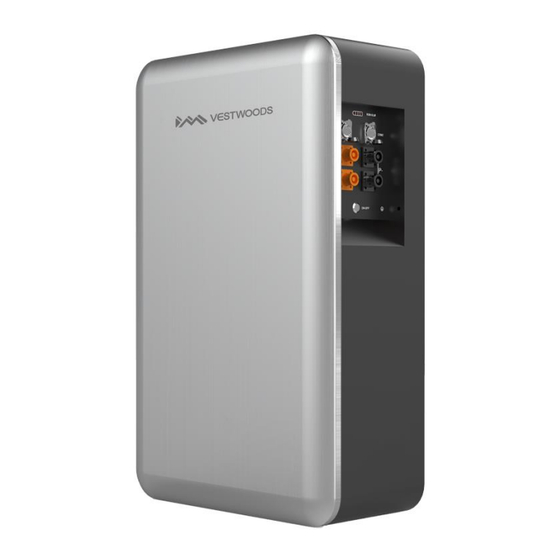
- Page 1 RESIDENTIAL ESS LITHIUM-ION BATTERY SOLUTION VE51280W...
- Page 2 About This Document Purpose This document primarily introduces the main features, component composition, usage, installation, and maintenance of Wall-mounted Residential Energy Storage System VE51280W (short for V-Power S14). Intended Audience This document is intended for: Hardware installation engineers ...
-
Page 3: Table Of Contents
Contents 1 Introduction ..........................1 1.1 Application ............................... 1 1.2 Appearance .............................. 1 1.3 Panel Introduction ............................ 2 1.4 PIN Definition ............................4 1.5 Lithium-ion Cell ............................5 1.6 Technical specifications ..........................6 2 Installation ..........................8 2.1 Precautions for Installation ........................8 2.2 Preparing for Installation .......................... -
Page 4: Introduction
1 Introduction 1.1 Application V-Power S14 is a next-generation product developed by Vestwoods, which is used in residential energy storage solutions. This battery system has a capacity of 14.336 kWh. V-Power S14 integrates the high-performance BMS. To extend battery life, it has multiple protection functions such as system over-charge, system over-discharge, cell over-voltage, cell under-voltage, charging over-current, discharging over-current, and insulation fault protections. -
Page 5: Panel Introduction
Figure 2. V-Power S14 dimensions (unit: mm) 1.3 Panel Introduction The V-Power S14 operation panel is shown as follows. Figure 3. V-Power S14 operation panel... - Page 6 The definition of the V-Power S14 operation panel is shown as follows. Table 1. Operation Panel Interface Definition Items Remark State of charge. RUN/ALM Indicate battery module running or alarm status. 2*RJ45 Interface for communication: COM 1/COM 2 COM1 for communication with inverter or the last battery; COM2 for communication with the next battery.
-
Page 7: Pin Definition
Indicator Light Definition Green LED ON Indicates the V-Power S14 is in standby mode. Red LED Blink Indicates the V-Power S14 is in alarm mode. Indicates an error has occur in the battery module, which requires manual Red LED ON operation or consultation with Vestwoods for maintenance. -
Page 8: Lithium-Ion Cell
1.5 Lithium-ion Cell The lithium Lithium-ion cell selected in the scheme is a special energy-type lithium battery product. This series of Lithium-ion cells have high specific energy, longer cycle life, low cost, capable of high current charge and discharge, high-temperature tolerance, high energy density, safety, and pollution-free features. Lithium-ion cell's three views are shown as follows. -
Page 9: Technical Specifications
Approx. 5.42 kg 1.6 Technical specifications The V-Power S14's main technical specifications are shown as follows. Table 6. V-Power S14 technical specifications Items Parameter Model VE51280W The number of cells Configuration 1P16S Nominal voltage 51.2 V Nominal capacity 280 Ah Total energy 14.336 kWh... - Page 10 Items Parameter Operating temperature Discharge -20℃ ~ 55℃, Charge 0℃ ~50℃ SOC estimation value <8% Allowable relative humidity 5% ~ 95% Non-condensing Altitude 2000m without derating Cooling method Natural heat dissipation Protection level IP65 Battery positive and negative quick plug terminals: External Interface 2*P+, 2*P- Communication standard RJ45 port:2*RJ45...
-
Page 11: Installation
2 Installation 2.1 Precautions for Installation Light intensity is required near the installation location. Comply with the safety operation technical regulations when lifting and handling heavy objects. Equipment and tools must be complete, intact, and reliable. It is strictly prohibited to use tools with cracks, burrs, loose handles, etc., that do not meet the safety standards. -
Page 12: Packing List
Diagonal pliers Claw hammer Multimeter Anti-static gloves Helmet Goggle Insulation shoes Insulating tape 2.2.2 Packing List Open the package and take out the product, please check the accessories first. The packing is shown below. Figure 5. Accessories of V-Power S14... -
Page 13: Unpacking Acceptance
Item Description Quantity Lithium battery pack Positive output power cable Negative output power cable Positive power parallel cable (*Optional) Negative power parallel cable (*Optional) Communication cable Parallel communication cable(*Optional) GND cable Resistance connector Protection cover, red & black Mounting base Expansion screw Spirit level User manual/Packing List/Warranty card... - Page 14 Take out the V-Power S14 and put it in the installation place. The V-Power S14 is heavy. If possible, please use tools to assist in handling and installation. Plan the installation site. Table 8. Installation Space Requirement Position Min. distance Left-side 100 mm Right-side...
-
Page 15: Connecting Power Cable
Figure 8. V-Power S14 grounding 2.4 Connecting Power Cable Context 1. Insulate installation tools to prevent electric shocks. 2. According to the power value of the inverter, the power cable should be connected. If multiple batteries are used in parallel, the power cables should be connected according to the wiring mode in Figure 11~13. 3. - Page 16 Figure 9. Self-locking connector button Procedure Connect the power cables of V-Power S14. Figure 10. Connect the external cables If there are multiple V-Power S14 in parallel, you need to connect them in parallel using the parallel power cables, then connect the power cable to the inverter. Please pay attention to the distinction between battery modules’...
- Page 17 Figure 11. Connect the power cables (Battery=2) Figure 12. Connect the power cables (2 < Batteries ≤ 4)
-
Page 18: Connecting Communication Cable
Figure 13. Connect the power cables (4 < Batteries ≤ 8) The self-locking connector's color should correspond to the V-Power S14 terminal's color: orange corresponds to the positive pole, and black corresponds to the negative pole. Please take care of the removed V-Power S14 protective cover in case of backup. 2.5 Connecting Communication Cable Context ... - Page 19 Figure 14. Connect the communication cables If there are multiple V-Power S14 in parallel, you need to connect the communication cables in parallel first. Then connect the communication cable between the inverter and COM1 of the first V-Power S14. Figure 15. Connect the communication cables (Battery=2)
- Page 20 Figure 16. Connect the communication cables (2 < Batteries ≤ 4) Figure 17. Connect the communication cables (4 < Batteries ≤ 8)
- Page 21 For the wiring diagram of the inverter to the user side, please refer to the user manual of inverter. Please confirm the usage scenarios of the inverter according to the actual situation. For details, please refer to the user manual of inverter. ...
-
Page 22: Operation
3 Operation 3.1 Check before Power-on Context After installing the V-Power S14, users need to perform a pre-power check to ensure that the device installation and cable connection are correct before performing the power-on operation. Procedure Check whether the V-Power S14 sequence is consistent with the layout diagram. Check the cable connection on site. - Page 23 Context 1. Before performing the power-on commissioning on the V-Power S14, users must strictly perform the pre-power-on check. 2. All batteries should have the 50% factory capacity. 3. Module parallel connection requirements: the total voltage difference between modules should not exceed 2V. 4.
-
Page 24: Operation Guide
Turn on the ON/OFF switch of the battery that used for connect communication to the next battery. Repeat the last step, until the last battery Run/Alarm indicator lights from green blinking into green, means power on normally. Batteries expand power on: ... -
Page 25: Maintenance
4 Maintenance The engineering personnel who perform the following operations must have received professional training. Before operating and maintaining the V-Power S14, wear anti-static work clothes, anti-static gloves, and wrist straps, and remove conductive objects such as jewelry and watches to avoid electric shock or burns. ... -
Page 26: Quarterly Maintenance
Table 9. Monthly maintenance Item Refer Standard Abnormal Handling Suggestion The appearance is neat and clean without If there is dirt on the surface, clean the V- stains. Power S14's appearance with a cotton cloth. The V-Power S14 terminals are intact. ... - Page 27 Table12. Alarm handling Phenomenon Possible failure Handling method Check: Ensure that the communication cable between the inverter and battery is properly connected. View the battery data on the inverter display or the inverter APP. If battery temperature ≤ 0℃ while the battery is charging, the battery under temperature alarm is generated.
-
Page 28: Acronyms And Abbreviations
Acronyms and Abbreviations Alternating Current Battery Management System Direct Current State of Charge...
Need help?
Do you have a question about the VE51280W and is the answer not in the manual?
Questions and answers