Table of Contents
Advertisement
Quick Links
WEEE Number: 80133970
INSTRUCTION MANUAL
14.33kWh WALL MOUNTED LITHIUM BATTERY
MODEL
SKU
VT-48280-W2
11525
INTRODUCTION
Thank you for selecting and buying V-TAC Product. V-TAC will serve youthe
best. Please read these instructions carefully & keep this user manualhandy for
future reference. If you have any another query, please contact our dealer or
local vendor from whom you have purchased the product. They are trained and
ready to serve you at the best.
MULTI-LANGUAGE MANUAL QR CODE
Please scan the QR code to access the manual in
multiple languages.
IN CASE OF ANY QUERY/ISSUE WITH THE PRODUCT, PLEASE REACH OUT TO US AT: SUPPORT@V-TAC.EU
FOR MORE PRODUCTS RANGE, INQUIRY PLEASE CONTACT OUR DISTRIBUTOR OR NEAREST DEALERS.
V-TAC EUROPE LTD. BULGARIA, PLOVDIV 4000, BUL.L.KARAVELOW 9B
Advertisement
Table of Contents

Related Manuals for V-TAC VT-48280-W2


Summary of Contents for V-TAC VT-48280-W2
- Page 1 Please scan the QR code to access the manual in multiple languages. IN CASE OF ANY QUERY/ISSUE WITH THE PRODUCT, PLEASE REACH OUT TO US AT: SUPPORT@V-TAC.EU FOR MORE PRODUCTS RANGE, INQUIRY PLEASE CONTACT OUR DISTRIBUTOR OR NEAREST DEALERS. V-TAC EUROPE LTD. BULGARIA, PLOVDIV 4000, BUL.L.KARAVELOW 9B...
-
Page 2: About This Document
About This Document Purpose This document primarily introduces the main features, component composi�on, usage, installa�on, and maintenance of Wall-mounted Residen�al Energy Storage System VE51280W (short for V-Power S14). Intended Audience This document is intended for: Hardware installa�on engineers Technical support engineers Maintenance engineers Users Symbol Conven�ons... -
Page 3: Table Of Contents
Contents About This Document ........................1 Introduc�on ..........................3 Applica�on ............................3 Appearance ............................3 Panel Introduc�on..........................4 PIN Defini�on ............................6 Lithium-ion Cell ............................ 7 Technical specifica�ons ........................8 Installa�on ..........................10 Precau�ons for Installa�on ........................ 10 Preparing for Installa�on........................10 2.2.1 Tools ................................ -
Page 4: Introduc�On
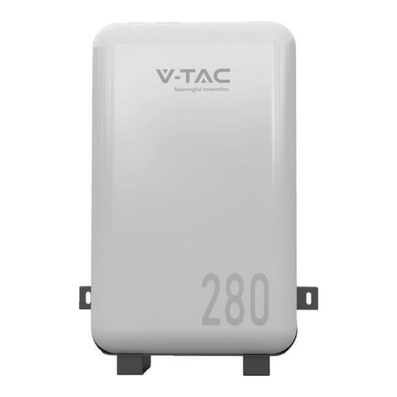
VT-48280-W2 VT-48280-W2 VT-48280-W2 Figure 1. VT-48280-W2 Appearance VT-48280-W2... -
Page 5: Panel Introduc�On
Figure 2. VT-48280-W2 Dimensions (Unit:mm) VT-48280-W2 Figure 3. VT-48280-W2 Operation Panel... - Page 6 The definition of the VT-48280-W2 operation panel is shown as follows. VT-48280-W2 VT-48280-W2...
-
Page 7: Pin Defini�On
VT-48280-W2 VT-48280-W2... -
Page 8: Lithium-Ion Cell
1.5 Lithium-ion Cell The lithium iron phosphate cell selected in the scheme is a special energy-type lithium ba�ery product. This series of lithium iron phosphate cells have high specific energy, longer cycle life, low cost, capable of high current charge and discharge, high-temperature tolerance, high energy density, safety, and pollu�on- free features. -
Page 9: Technical Specifica�Ons
VT-48280-W2 VT-48280-W2... - Page 10 Items Parameter Storage temperature ~ 45 Opera�ng temperature Discharge -20 ~ 55°C, Charge 0°C ~50 SOC es�ma�on value <8% Allowable rela�ve humidity 5% ~ 95% Non-condensing Al�tude 2000m without dera�ng Cooling method Natural heat dissipa�on Protec�on level IP65 Ba�ery posi�ve and nega�ve quick plug terminals: External Interface 2*P+, 2*P- Communica�on standard RJ45 port:2*RJ45...
-
Page 11: Installa�On
2 Installa�on 2.1 Precau�ons for Installa�on Light intensity is required near the installa�on loca�on. Comply with the safety opera�on technical regula�ons when li�ing and handling heavy objects. Equipment and tools must be complete, intact, and reliable. It is strictly prohibited to use tools with cracks, burrs, loose handles, etc., that do not meet the safety standards. -
Page 12: Packing List
VT-48280-W2... -
Page 13: Unpacking Acceptance
VT-48280-W2 VT-48280-W2 VT-48280-W2 VT-48280-W2 VT-48280-W2 VT-48280-W2... -
Page 14: Connec�Ng Power Cable
VT-48280-W2 VT-48280-W2 VT-48280-W2... - Page 15 Figure 9. power cable connec�on method adopts a self - locking connector. The descrip�on of VT-48280-W2 the self-locking connector is shown as follows: The steps for connec�ng the self-locking connector are as follows: Adjust the direc�on of the self-locking connector to align with the...
- Page 16 Connect the P+ & P- power cables to the inverter. Figure 10. Connect the external cables The self-locking connector's color should correspond to the VT-48280-W2 terminal's color: orange corresponds to the posi�ve pole, and black corresponds to the nega�ve pole.
-
Page 17: Connec�Ng Communica�On Cable
Communica�on cables and power cables must be routed separately. If there are mul�ple in parallel, you need to connect the communica�on cables in parallel VT-48280-W2 first. Then you need to connect the communica�on cable of the inverter to COM1 of any VT-48280-W2 Procedure Connect the internal communica�on cables of the... - Page 18 For the wiring diagram of the inverter to the user side, please refer to the user manual of inverter. Please confirm the usage scenarios of the inverter according to the actual situa�on. For details, please refer to the user manual of inverter. The communica�on cable to the inverter contains L&N cable (220V power supply for BMS).
-
Page 19: Opera�On
VT-48280-W2 VT-48280-W2 VT-48280-W2 VT-48280-W2... -
Page 20: Opera�On Guide
VT-48280-W2... - Page 21 VT-48280-W2...
-
Page 22: Maintenance
VT-48280-W2 VT-48280-W2 VT-48280-W2 VT-48280-W2 VT-48280-W2 VT-48280-W2 VT-48280-W2 VT-48280-W2 VT-48280-W2 VT-48280-W2... -
Page 23: Quarterly Maintenance
VT-48280-W2 VT-48280-W2 VT-48280-W2 VT-48280-W2 VT-48280-W2 VT-48280-W2... -
Page 24: Alarm Handling
Table12. Alarm handling Phenomenon Possible failure Handling method Check: Ensure that the communica�on cable between the inverter and ba�ery is properly connected. View the ba�ery data on the inverter display or the inverter APP. generated the under voltage alarm. Cell or ba�ery under voltage generated the over voltage alarm. -
Page 25: Acronyms And Abbrevia�Ons
Acronyms and Abbrevia�ons Alterna�ng Current Ba�ery Management unit Ba�ery Management System Ba�ery Control Unit Direct Current Protocol Converter Unit State of Charge State of Health...
Need help?
Do you have a question about the VT-48280-W2 and is the answer not in the manual?
Questions and answers