Table of Contents
Advertisement
Quick Links
Thank you for selecting and buying V-TAC Product. V-TAC will serve you
the best. Please read these instructions carefully & keep this user manual
handy for future reference. If you have any another query, please contact
our dealer or local vendor from whom you have purchased the product.
They are trained and ready to serve you at the best.
IN CASE OF ANY QUERY/ISSUE WITH THE PRODUCT, PLEASE REACH OUT TO US AT: SUPPORT@V-TAC.EU
FOR MORE PRODUCTS RANGE, INQUIRY PLEASE CONTACT OUR DISTRIBUTOR OR NEAREST
DEALERS. V-TAC EUROPE LTD. BULGARIA, PLOVDIV 4000, BUL.L.KARAVELOW 9B
INSTRUCTION MANUAL
ESS SERIES BATTERY PACK
MODEL
VT-204100
INTRODUCTION
Multi-Language Manual QR CODE
Please scan the QR code to access the manual
in multiple languages.
SKU
11527
Advertisement
Table of Contents

Subscribe to Our Youtube Channel
Related Manuals for V-TAC VT-204100


Summary of Contents for V-TAC VT-204100
- Page 1 Please scan the QR code to access the manual in multiple languages. IN CASE OF ANY QUERY/ISSUE WITH THE PRODUCT, PLEASE REACH OUT TO US AT: SUPPORT@V-TAC.EU FOR MORE PRODUCTS RANGE, INQUIRY PLEASE CONTACT OUR DISTRIBUTOR OR NEAREST DEALERS. V-TAC EUROPE LTD. BULGARIA, PLOVDIV 4000, BUL.L.KARAVELOW 9B...
-
Page 2: About This Document
About This Document Intended Audience This document is intended for: Hardware installation engineers Technical support engineers Maintenance engineers Users Symbol Conventions The symbols that may be found in this document are defined as follows. Symbol Definition Remarks Indicates a hazard with a high level of risk which, if not avoided, will Danger result in death or serious injury. - Page 3 VT-204100 VT-204100 VT-204100 VT-204100 VT-204100...
-
Page 4: Components Introduction
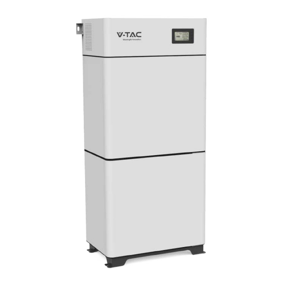
3 Components Introduction 3.1 Battery Cabinet The appearance of the battery cabinet is shown as follows. Figure 2. Battery cabinet appearance The battery cabinet dimensions are shown as follows: Figure 3. Battery cabinet dimensions (unit: mm) -
Page 5: Battery System
3.2 Battery System The battery system specifications are as follows. Table 1. Battery system specifications Items Parameter Remark VEH192100C: 192 V Rated voltage VEH204100C: 204.8 V Rated capacity 100 Ah VEH192100C: 19.2 kWh Rated energy VEH204100C: 20.48 kWh System efficiency Watt-hour efficiency Communication type CAN、RS485、DO/DI... -
Page 7: Technical Specifications
3.2.1.2 Technical Specifications Lithium-ion cell main technical specifications are shown as follows. Table 2. Lithium-ion cell main technical specifications Items Specification Battery type Lithium iron phosphate Model LF100MA Rated voltage 3.2 V Rated capacity 100 Ah Rated energy 0.32 kWh Max continuous charge current 100 A Max continuous discharge current... -
Page 8: Operation Panel
3.2.2.1 Appearance The battery module appearance is shown as follows. Figure 5. Battery module appearance The battery module's three views are shown as follows. Figure 6. Battery module three views (unit: mm) 3.2.2.2 Operation Panel The battery module operation panel is shown as follows. -
Page 9: Pin Definition
Figure 7. Battery module operation panel The definition of the battery module operation panel is shown as follows. Table 3. Operation panel definition Items Remark Communicate with other battery modules; Communication port Communicate with high-voltage box. Running indicator Indicate battery module running status. Reset switch Reset BMU. - Page 12 Figure 11. High-voltage box three views (unit: mm) 3.2.4.2 Operation Panel The operation panel of the high-voltage box is shown as follows. Figure 12. High-voltage box operation panel The definition of the high-voltage box operation panel is shown as follows. Table 6.
- Page 13 3.2.4.3 PIN Definition External communication port The PIN definition of an external communication port is shown as follows. Table 7. External communication port PIN definition Location schematic diagram Location Definition Remark CAN1H BCU communication, connect the last high voltage box Optional (...
- Page 14 VT-204100...
- Page 15 Battery module management module: BMU, integrated with the battery module. Battery cluster management module: BCU, integrated with the high voltage box. Battery system management module: PCU, integrated with the high voltage box. BMS can monitor the current, voltage, and temperature of cells in the battery module in real-time, calculate the SOC of the battery system, communicate with the host computer software, and send fault and alarm information.
- Page 16 Item Specification Remark Equalization Negative equalization ≤ 300 mA Operation temperature -20℃~75℃ Operation humidity 5%-95%RH 3.3.2 BCU The BCU integrated with the high-voltage box is the intermediate level of the BMS. It collects information from the BMU and transmits it to the PCU. BCU can effectively manage the safety of charge and discharge of battery clusters, provide real-time monitoring of battery parameters, fault diagnosis, SOC/SOH estimation, insulation detection, remote monitoring, and other functions, and trigger protection when alarm and emergency battery module...
- Page 17 The PCU integrated with the high-voltage box can monitor and manage battery clusters internally and complete information exchange externally. The main functions of the PCU are as follows: Battery information management: PCU can monitor cell voltage, cell temperature, cluster voltage, cluster charging current, and cluster discharging current in real-time.
- Page 19 VT-204100...
- Page 21 The battery box 2 fixing. Install 2 pcs guide rails of battery box 1 first, then align the lower notch of battery box 2 with the upper guide of battery box 1, lower it and push it to the right. Facilitate pushing to the right, the coil can be removed before assembly.
- Page 22 Figure 18. Fixing the high-voltage box Whole machine fixing, drill holes according to the position of the battery cabinet installation holes. The top is fixed to the wall, and the bottom is fixed to the ground, using M6 Expansion screws. If the battery cabinet is installed against the wall, it can be fixed on the wall.
- Page 23 Figure 20. Installing expansion bolts (unit: mm) Drill holes in the ground by using a hammer drill. Partially tighten the expansion bolt and vertically insert it into the hole. Hit the expansion bolt using a hammer until the expansion sleeve is fully inserted into the hole. Partially tighten the expansion bolt.
-
Page 24: Installing Battery Module
4.4 Installing Battery Module Procedure Take out the battery module and put it in the installation place. The battery module is heavy. If possible, please use tools to assist in handling and installation. The address of the battery module can be automatically assigned after the battery module is powered on. Fixing the battery modules to the cabinet with the cross-recessed pan head combination screws. -
Page 25: Connecting Power Cable
Figure 23. Battery module grounding 4.5 Connecting Power Cable Context Insulate installation tools to prevent electric shocks. The battery module power cable connection method adopts the self-locking connector method. The description of the self-locking connector is shown as follows: The steps for connecting the self-locking connector are as follows: Adjust the direction of the self-locking connector to align with the battery module terminal. - Page 26 Figure 24. Self-locking connector button Procedure Connect the power cable between the high-voltage box and the battery module. The self-locking connector's color should correspond to the battery module terminal's color: orange corresponds to the positive pole, and black corresponds to the negative pole. The internal wiring of the battery cabinet is the same.
- Page 27 VT-204100...
- Page 28 Connect the remaining power cables and signal cables between the battery cabinet and inverter. Figure 27. Connect the external cables For the wiring diagram of the inverter to the user side, please refer to the inverter user manual. Please confirm the usage scenarios of the inverter according to the actual situation. For details, please refer to the inverter user manual.
- Page 29 VT-204100...
- Page 30 5.3 Operation Guide The battery system has completed the system parameter settings at the factory, and the system will run automatically after power is on. The inverter needs to be set according to actual needs. For detailed operations, please refer to the User Manual.
- Page 31 VT-204100...
-
Page 32: Quarterly Maintenance
Users should conduct a visual inspection of the RESS monthly. Please refer to the following table for monthly maintenance. Table 14. Monthly maintenance Item Refer Standard Abnormal Handling Suggestion The appearance is neat and clean without If there is dirt on the surface, clean the stains. -
Page 33: Acronyms And Abbreviations
Acronyms and Abbreviations Alternating Current Battery Management unit Battery Management System Battery Control Unit Direct Current Protocol Converter Unit State of Charge State of Health...
Need help?
Do you have a question about the VT-204100 and is the answer not in the manual?
Questions and answers