Table of Contents
Advertisement
Quick Links
Advertisement
Table of Contents
Troubleshooting

Related Manuals for Minolta MAGICOLOR 2300


Summary of Contents for Minolta MAGICOLOR 2300
- Page 1 2300 Series Service Manual 1750058-001C...
-
Page 2: Proprietary Statement
MINOLTA-QMS, Inc. Copyright Notice This manual is Copyrighted © 2002 by MINOLTA-QMS, Inc., One Magnum Pass, Mobile, AL 36618. All Rights Reserved. This document may not be copied, in whole or part, nor transferred to any other media or language, without written permission of MINOLTA-QMS, Inc. -
Page 3: Contents
CONTENTS... -
Page 5: Table Of Contents
CONTENTS ..............3 SAFETY ...............9 Safety Precautions for Inspection and Service ..........11 Warning ....................... 11 Caution ......................13 Used Batteries Precautions ................. 15 Other Precautions ..................16 Precautions for Service ................16 Safety information ..................19 Laser Safety Label ..................22 Laser Caution Label .................. - Page 6 Control Panel Descriptions—2300DL & 2350 ..........129 Names of control panel parts and their functions ........129 Message Window ..................129 Menu Contents for magicolor 2300 DL ............133 Print menu overview .................. 133 Settings menus ..................134 Service Mode .................... 136 Service mode displays ................
- Page 7 Using the Status Display ................143 Status, Error and Service Messages ............144 TROUBLESHOOTING ..........147 Introduction ...................... 149 Checking the electrical components ............149 Paper Misfeeds ....................152 Perform initial check procedures ............... 152 Paper misfeed displays ................153 Wiring diagram of misfeed-detecting sensors ..........154 Misfeed detection timing and remedies .............
-
Page 9: Safety
SAFETY... -
Page 11: Safety Precautions For Inspection And Service
SAFETY PRECAUTIONS FOR INSPECTION AND SERVICE • When performing inspection and service procedures, observe the following precautions to prevent accidents and ensure utmost safety. Depending on the model, some of the precautions listed below do not apply. • Different markings are used to denote specific meanings as detailed below. WARNING •... - Page 12 • This product contains a high-voltage unit and a circuit with a large current capacity that may cause an electric shock or burn. • The product also contains parts that can jerk suddenly and cause injury. • If this product uses a laser, laser beam leakage may cause eye damage or blindness.
-
Page 13: Caution
WARNING 9. Maintain a Grounded Connection at all times. • Connect the power cord to an electrical outlet that is equipped with a ground- ing terminal. 10. Do not remodel the product. • Modifying this product in a manner not authorized by the manufacturer may result in a fire or electric shock. - Page 14 CAUTION 2. Precautions for Servicing with Covers and Parts Removed. • Wherever feasible, keep all parts and covers mounted when energizing the product. • If energizing the product with a cover removed is absolutely unavoidable, do not touch any exposed live parts and use care not to allow your clothing to be caught in the moving parts.
-
Page 15: Used Batteries Precautions
1-3. Used Batteries Precautions ALL Areas CAUTION Danger of explosion if battery is incorrectly replaced. Replace only with the same or equivalent type recommended by the manufacturer. Dispose of used batteries according to the manufacturer’s instructions. Germany VORSICHT! Explosionsgefahr bei unsachgemäßem Austausch der Batterie. Ersatz nur durch denselben oder einen vom Hersteller empfohlenen gleichwertigen Typ. -
Page 16: Other Precautions
1-4. Other Precautions • When handling circuit boards, observe the “HANDLING of PWBs”. • The PC Drum is a very delicate component. Observe the precautions given in “HAN- DLING OF THE PC DRUM” because mishandling may result in serious image problems. •... - Page 17 4. Precautions for Dis/Reassembly • Be sure to unplug the printer from the outlet before attempting to service the printer. • The basic rule is not to operate the printer anytime during disassembly. If it is absolutely necessary to run the printer with its covers removed, use care not to allow your clothing to be caught in revolving parts such as the timing belt and gears.
- Page 18 8. Handling of the Imaging Cartridge During Transportation/Storage • The storage temperature is in the range between –20 °C and +40 °C. • In summer, avoid leaving the Imaging Cartridge in a car for a long time. Handling • Store the Imaging Cartridge in a place that is not exposed to direct sunlight. Precautionary Information on the PC Drum Inside the Imaging Cartridge •...
-
Page 19: Safety Information
1-6. Safety information Laser Safety • This is a digital machine certified as a class 1 laser product. There is no possibility of danger from a laser, provided the machine is serviced according to the instruction in this manual. Internal Laser Radiation semiconductor laser Maximum average radiation power(*) 4.68 µW... - Page 20 the U.S.A., Canada (CDRH Regulation) • This machine is certified as a Class I Laser product under Radiation Performance Stan- dard according to the Food, Drug and Cosmetic Act of 1990. Compliance is mandatory for Laser products marketed in the United States and is reported to the Center for Devices and Radiological Health (CDRH) of the U.S.
- Page 21 Finland, Sweden LUOKAN 1 LASERLAITE KLASS 1 LASER APPARAT VAROITUS! Laitteen käyttäminen muulla kuin tässä käyttöohjeessa mainitulla tavalla saattaa altistaa käyttäjän turvallisuusluokan 1 ylittävälle näkymättömälle lasersäteilylle. puolijohdelaser Laserdiodin suurin teho 5 mW aallonpituus 770-795 nm VARNING! Om apparaten används på annat sätt än i denna bruksanvisning specificerats, kan användaren utsättas för osynlig laserstrålning, som överskrider gränsen för laserklass 1.
-
Page 22: Laser Safety Label
1-7. Laser Safety Label • A laser safety label is attached to the outside of the machine as shown below. for 120V for 220 - 240V for 100V 4131o003AA 1-8. Laser Caution Label • A laser caution label is attached to the inside of the machine as shown below. C4131s005AA... -
Page 23: Precautions For Handling The Laser Equipment
1-9. PRECAUTIONS FOR HANDLING THE LASER EQUIPMENT • When laser protective goggles are to be used, select ones with a lens conforming to the above specifications. • When a disassembly job needs to be performed in the laser beam path, such as when working around the printerhead and PC Drum, be sure first to turn the printer OFF. -
Page 25: General
GENERAL... -
Page 27: Product Specifications
Product Specifications Printer Type Desktop full-color laser beam printer Printing method Electrophotographic (two-part imaging cartridge) Exposure method Laser diode and polygon mirror scanning Print resolution 600 dpi (dots/inch) Media sizes A5T, B5T, A4, Letter, Legal Plain paper (16-24 lb bond, 60-90 g/m2), recycled paper, overhead projector transparencies, letterheads, envelopes (Monarch, Com-10, Media types DL, C5, C6, Chokei -3, Chokei -4), label sheets, thick paper (91-163... - Page 28 50-95° F (10-35°C) Operating environment 15 - 85% Drum cartridge life 45,000 pages (black/white ratio=5%) 4,500 pages (black/white ratio=5%) Toner cartridge life (purchased separately) 1,500 pages (black/white ratio=5%) Black: 1,500 pages (black/white ratio=5%) Toner cartridge life (enclosed cartridge) Color: 1,500 pages (color/white ratio for each color=5%) Second paper cassette (2300 DL &...
- Page 29 Controller magicolor 2300DL (PWB-P) D8405 200MHz Standard ROM: 4MB Memory configuration Standard RAM: 32MB Ethernet (10/100BASE-TX, RJ-45) Standard I/F IEEE1284 (Compatible/Nibble/ECP/EPP) USB Type B connector TCP/IP Network protocol DHCP, ARP/ICMP, BOOTP, SLP, IPP, HTTP, SNMP, LPR RAW Port Printing (9100) Network print service IPP1.0 (http://Printer IP address/ipp.cgi) LPD (Queue Name: lp, LP, default, DEFAULT)
- Page 30 Controller magicolor 2350 (PWB-P) IBM Mercury, Power PC 405, 200 Mhz processor core SOC, system bus speed of 100 Mhz Memory configuration Boot ROM (512KB); 12MB Flash ROM (supports up to 24MB) 128 MB standard, upgreadeable to 384 MB via 1 DIMM slot Standard I/F Ethernet (10/100BASE-TX, RJ-45) IEEE1284 (Compatible/Nibble/ECP/EPP)
-
Page 31: Installation Precautions
Installation Precautions 2-1. Installation environment To ensure safety and prevent possible malfunctions, install the unit in a location that meets the following requirements. • A location that is not exposed to extremely high or low temperatures and not exposed to extremely high or low humidity. -
Page 32: Space Requirements
2-3. Space requirements • 13.4 in. (340 mm) 27.8 in. (705 mm) 4131o103AA 19.7 in. (500 mm) 11.8 in. (300 mm) C4131o105AA... -
Page 33: Operation Precautions
Operation Precautions 3-1. Ensuring the optimum performance of this unit • Never place heavy objects on the unit or subject it to shocks. • Make sure that the power supply plug is securely inserted into the electrical outlet. • Never remove secured panels or open doors of the unit while it is printing. •... -
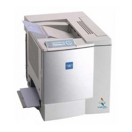
Page 34: Parts Identification
3-5. Parts Identification 4131o001AA 4131o106AA 4131g002AA 4131g003AA 4131g004AA 4131o107AA Manual feed tray Power switch Image transfer belt unit Waste toner bottle Drum cartridge Toner cartridge Right-side door release lever Duplex unit (optional) -
Page 35: Mechanical/ Electrical
MECHANICAL/ ELECTRICAL... -
Page 37: Cross-Sectional View
CROSS-SECTIONAL VIEW 4131M001AA 1. Toner Cartridge Rack 8. Transport Roller 2. PC Drum 9. Paper Take-Up Roller 3. Image Transfer Belt Unit 10. Second Paper Take-Up 4. Exit Roller Roller 5. Fusing Roller 6. Second Image Transfer Roller 7. Synchronizing Roller Paper Path The printer has a Multi-Purpose Tray (MPT) capable of holding up to 200 sheets of paper. -
Page 38: Electrical Components Layout
ELECTRICAL COMPONENTS LAYOUT Printer 4131D002AA... - Page 39 1. Fusing Roller Heater Lamp (H1) 29. Belt Cleaner Positioning Sensor 2. Fusing Pressure Roller Heater Lamp (PC9) (H2) 30. Rack Motor (M2) 3. Thermistor (TH1) 31. AIDC Sensor (AIDC) 4. Thermostat (TS1) 32. Main Motor (M1) 5. Second Image Transfer Roller Pres- 33.
- Page 40 2300DL Controller 4131M039AA Symbol Item Explanation Destiny D8405 200 MHz controller control CPU U26, U27, SDRAM 8-MB memory chip, a total of 32 MB standard memory U28, U29 68-pin SD-RAM add-on memory (128, 256 MB, PC100/ CON4 Expansion slot 133 CL3) Connector 10/100Base-T Ethernet RJ45 connector Ethernet Controller...
- Page 41 2350 Controller JP10 Symbol Item Explanation 200 MHz Power PC 405 CPU U3, U6, U10, U12, U16, SDRAM A total of 128 MB standard memory U19, U24, U30 68-pin SD-RAM add-on memory (128, 256 MB, PC100/ Expansion slot 133 CL3) Connector 10/100Base-T Ethernet RJ45 connector Connector...
- Page 42 2300W Controller Controller Panel Interface Connector Demonstration ROM Board Connector Image memory Controller ASIC Image memory 4131M554AA Engine Controller connector Parallel/USB Interface Connector...
-
Page 43: Operating Sequence
OPERATING SEQUENCE Conditions: A4 plain paper, full-color printing 4131M043AA... -
Page 44: Image Stabilization Control
IMAGE STABILIZATION CONTROL • The printer provides the image stabilization control as detailed below to ensure stabilized print image. Purpose Control Control (Sensor) • To stabilize image AIDC Sensor (AIDC density AIDC control detection) • To stabilize gradation • To stabilize image Temperature/Humidity Image transfer output control transfer... -
Page 45: Outline Of Aidc Control
4-2. Outline of AIDC Control • The following AIDC controls are provided to ensure image stabilization. Control Description • Ds correction control • Sets the developing bias. • LED intensity adjustment • Adjusts the intensity of the LED light. control •... -
Page 46: Operation Timing
4-3. Operation Timing • A specific function of image stabilization control is carried out as required according to the situation. Operating Timing Processing • When a new Image Transfer Belt • Ds correction control -> LED intensity is detected adjustment control -> Belt surface reflec- •... -
Page 47: Temperature/Humidity Sensor
4-4. Temperature/Humidity Sensor • The bias voltage is determined based on the value calculated through ATVC (Auto Transfer Voltage Control) and by the Temperature/Humidity Sensor (environment). Temperature/Humidity Sensor (HS1) 4131M038AA Temperature Data ATVC Control Humidity Data Master Board (PWB-A) 4131m029AA High Voltage Unit (HV) Second Image Transfer Bias... -
Page 48: Atvc
4-5. ATVC (Auto Transfer Voltage Control • Adjusts the transfer bias voltage based on the age and cleanliness of the transfer rollers. ATVC Control Image Transfer Belt is cleaned Fixed current is output to first transfer roller Resistance of first transfer roller is measured First transfer voltage is determined Second transfer roller is cleaned... -
Page 49: Drum Cartridge
DRUM CARTRIDGE 5-1. PC Drum • The photoconductive drum used in this printer is the organic photo conductor (OPC) type. This is the PC Drum consisting of the Charge Generating Layer and the Charge Trans- port Layer applied to an aluminum alloy base. Handling Precaution The PC Drum exhibits light fatigue after being exposed to light for a long time, which results in its sensitivity being changed. -
Page 50: Pc Drum Charging
5-2. PC Drum Charging • The PC Drum Charge Corona employs a comb electrode Scorotron charger system. • It generates corona emission to deposit a charge evenly across the surface of the PC Drum through a grid mesh. • The comb electrode ensures that a charge is concentrated on the grid mesh, thus reduc- ing the amount of ozone produced. -
Page 51: Laser Exposure
LASER EXPOSURE An electrostatic latent image is formed on the surface of the PC Drum by a laser light emit- ted from the print head. Polygon Motor (M3) PC Drum 4131M005AB FD Direction (vertical scanning direction) • The Polygon Motor and Main Motor are energized by the PRINT signal, which starts a paper take-up sequence. - Page 52 Print Area • The figure below shows the print area in the FD and CD direction. /HSYNC /VIDEO /TOD /VIDEO Void Image Width: 4 mm CD Direction: 208 mm 80 ms Void Image Width: 4 mm 4131M046AA...
-
Page 53: Developing Unit
DEVELOPING UNIT Toner Cartridge Rack When printing in each of the four different colors of toner, the Toner Cartridge Rack is rotated to bring the Toner Cartridge of the corresponding color of toner (K, Y, M, or C) to the developing position. - Page 54 Drive for the Developing Roller • The Developing Roller is driven by the Rack Motor (M2) and the Developing Roller Drive Gears. • When the Toner Cartridge Rack is stopped at the developing position, the Developing Roller is rotated by a drive from the Rack Motor (M2) transmitted with the Developing Roller Drive Gears.
-
Page 55: Developing Position
7-1. Developing Position Toner Cartridge Rack Stop Position for Development • The stop position for development of each Toner Cartridge is determined by the Rack Lock Lever and the Rack Home Position Sensor (PC4). • The Toner Cartridge Rack rotates and the Rack Lock Lever drops into a stopping cutout. This unblocks the Rack Home Position Sensor (PC4), thus determining the stop position for the Toner Cartridge for the current use. -
Page 56: Toner Cartridge
7-2. Toner Cartridge Construction • The Toner Cartridge is constructed as illustrated below. 4131M050AA 4131M051AA 1. Toper Hopper 6. First Regulator Blade 2. Toner Agitating Plate 7. Second Regulator Blade 3. Toner Transport Roller 8. Bias Seal 4. Developing Roller 5. - Page 57 First Regulator Blade / Second Regulator Blade • Regulates the amount of toner supplied to the Developing Roller. Developing Roller • Carries toner, whose amount has been regulated by the Regulator Blades. Developing Bias • Applied to the Developing Roller to ensure that an adequate amount of toner is fed to the PC Drum.
- Page 58 Toner Cartridge Installation Detection • Toner Cartridge installation detection is made with the Toner Cartridge Detection Sensor (PC8) and the Reflector in the Toner Cartridge. Intensity of Light Reflected Detection No Cartridge installed Method Cartridge installed Reflector Reflector 4131M040AA 4131M039AA...
- Page 59 Detection of a brand new Toner Cartridge 1. A brand new Toner Cartridge is installed. 2. The Front Door is closed. Then, the Power Switch is turned ON. 3. The Toner Cartridge Rack is rotated to bring the Toner Cartridge at the develop- ing position.
-
Page 60: Image Transfer
IMAGE TRANSFER 8-1. Image Transfer Belt Unit Construction 4131M053AA 1. Image Transfer Belt 5. Drive Roller 2. Cleaning Blade 6. Second Image Transfer Roller 3. Waste Toner Conveying Coil 4. First Image Transfer Roller Drive Train 4131M009AA 1. Main Motor (M1) 2. - Page 61 First Image Transfer • The first image transfer bias is applied to the First Image Transfer Roller to transfer the toner image on the surface of the PC Drum onto the Image Transfer Belt. First Image Transfer Roller Image Transfer Belt First Image Transfer Bias 4131M054AA PC Drum...
- Page 62 Second Image Transfer Roller Pressure/Retraction • The Second Image Transfer Roller is pressed against, and retracted from, the Image Transfer Belt by a cam on the printer side that is turned as the Second Image Transfer Roller Pressure Contact Solenoid (SL5) is energized or de energized. •...
-
Page 63: Second Image Transfer Roller Cleaning
8-2. Second Image Transfer Roller Cleaning • A reverse bias is applied to the Second Image Transfer Roller to remove any residual toner left on the roller. • The residual toner is transferred onto the Image Transfer Belt and then recovered by the Cleaning Blade. -
Page 64: Image Transfer Belt Cleaning Mechanism
8-3. Image Transfer Belt Cleaning Mechanism Image Transfer Belt Cleaning Blade • The Cleaning Blade is used to scrape any residual toner off the surface of the Image Transfer Belt. Image Transfer Belt Positioning Sensor (PC5) Belt Cleaner Separation Solenoid (SL4) 4131M011AA Cleaning Blade Opposing Roller... - Page 65 Image Transfer Belt Cleaning Blade Retraction • The Image Transfer Belt Cleaning Blade is retracted from the Opposing Roller by a cam on the printer side that turns as the Belt Cleaner Separation Solenoid (SL4) is energized or deenergized. • The cam on the printer side is made into direct contact with the Cleaning Blade housing so that the Cleaning Blade is retracted.
-
Page 66: Waste Toner Bottle
8-4. Waste Toner Bottle • Waste toner on the PC Drum and the Image Transfer Belt is collected. • The waste toner sticking to the surface of the PC Drum is scraped off by the Cleaning Blade and conveyed by the Waste Toner Conveying Coil. •... -
Page 67: Fusing Section
FUSING SECTION 9-1. Fusing Unit Overview • Toner transferred onto the paper through the image transfer process is permanently fixed onto the paper. • The fusing system employed in the printer is a heat roller method, in which the Fusing Roller heated by a heater lamp is pressed against the Fusing Pressure Roller and, by feeding the paper between these two rollers, toner is fused onto the paper. - Page 68 Drive • The Fusing Unit is driven by the Main Motor (M1). Main Motor (M1) 4131M016AA Fusing Roller Pressure • The Fusing Roller and the Fusing Pressure Roller are pressed against each other at all times. They are released for maintenance service or replacement of parts. •...
-
Page 69: Fusing Temperature Control
9-2. Fusing Temperature Control Fusing Temperature Control Circuit • The resistance of the Thermistor (TH) mounted to the Fusing Roller varies with tempera- ture. The higher the temperature, the smaller the resistance value. The output from the Thermistor (TH) is applied to the analog port of the CPU. •... - Page 70 Fusing Temperature Control • The temperature control as detailed below is provided by means of the Fusing Roller Heater Lamp (H1) and the Fusing Pressure Roller Heater Lamp (H2). • The surface temperature of the Fusing Roller is converted by the Thermistor (TH1) to a corresponding electrical signal.
-
Page 71: 10. Paper Take-Up Section
10. PAPER TAKE-UP SECTION 10-1. Manual Feed Tray Paper Take-Up Mechanism • The Manual Feed Tray consists of a Paper Take-Up Roll, Paper Lifting Plate, and the Manual Feed Paper Take-Up Solenoid (SL1). • When the Manual Feed Paper Take-Up Solenoid (SL1) is energized, the cam turns. At the same time, the Paper Lifting Plate raises the tray and the paper on the tray is taken up by the Paper Take-Up Roll and fed into the printer. -
Page 72: Lower Feeder Unit (Option)
10-2. Lower Feeder Unit (Option) Paper Take-Up Mechanism • Since there is no drive motor installed, the drive for paper take-up and transport (supplied from M1) is transmitted through a drive coupling gear from the printer. • The same paper take-up mechanism is employed as that of the Multi-Purpose Tray, except that paper separator fingers are used, instead of the separator roll with a torque limiter, for paper separation. -
Page 73: 11. Other Mechanisms
11. OTHER MECHANISMS 11-1. Duplex Unit (Option) Drive • The drive for the Duplex Unit works as follows. The paper having a printed image on its one side is temporarily fed toward the Exit Tray and, as soon as the trailing edge of the paper moves past the guide plate before the Exit Roller, the Exit Roller is turned back- ward so that the paper is fed into the Duplex Unit. - Page 74 Paper Feeding Method 1. Operations in 2-sided printing with a single sheet of paper resident in, and circulated through, the system Paper is taken up and fed in and the image on page 2 of the print job is printed. 4657M521AA The paper is temporarily fed toward the exit section and, immediately before the paper...
- Page 75 The image on page 1 of the print job is printed on the paper that is taken up from the Duplex Unit. The first paper is fed out of the printer. 4657M524AA Steps from (2) to (6) are hereafter repeated.
- Page 76 2. Operations in 2-sided printing with two sheets of paper resident in, and circulated through, the system: The first sheet of paper is taken up and fed in and the image on page 2 of the print job is printed. 4657M515AA The first sheet of paper is temporarily fed toward the exit section and, immediately before...
- Page 77 The image on page 1 of the print job is printed on the first sheet of paper. (10) The second sheet of paper is transported into the Duplex Unit. 4657M519AA (11) At the same time that the first sheet of paper is fed out of the printer, the image on page 3 is printed on the second sheet of paper.
- Page 78 3. Operations in 2-sided printing with two sheets of paper resident in the system and with a new sheet of paper taken up when a printed page with images printed on both sides is fed out The first sheet of paper is taken up and fed in and the image on page 2 of the print job is printed.
- Page 79 (10) The first sheet of paper fed out in exit tray. (11) At the same time the third sheet of paper is taken up and fed in. (12) The second of sheet of paper stopped at take- up position. 4657M531AA (13) The image on page 3 is printed on the second sheet of paper.
-
Page 81: Maintenance & Disassembly/Assembly
MAINTENANCE & DISAS- SEMBLY/ASSEMBLY 19971... -
Page 83: Disassembly/Assembly Precautions
Disassembly/Assembly Precautions 1-1. Precautions for disassembly and assembly • Unplug the power cord from the electrical outlet before servicing the printer. • Reassemble the unit in reverse order of disassembly unless otherwise instructed. • If it is necessary to run the printer with its covers removed, use extreme care to avoid catching your fingers or clothing in rotating parts such as gears, rollers, or motors. -
Page 84: Precautions For Transporting Or Storing The Opc Drum Cartridge
• Use the specified carton when transporting or storing the OPC drum (magicolor 2350)/ PC drum (magicolor 2300 dl). • Do not store or place an OPC drum cartridge in a location where it will be exposed to direct sunlight. The storage temperature should be between -4°F(-20 C) to 104°F... -
Page 85: Maintenance Schedule
Maintenance Schedule Maintenance Cycle Near Life Ref. Page Life Print PM Parts Detec- in This Detec- Inhibited Clean Replace tion Manual tion When paper Paper Take-Up Roller take-up failure 200K Prints occurs When paper Separator Roller Assy take-up failure 200K Prints occurs When paper Paper Dust Roller... - Page 86 NOTES Replace the Paper Take-Up Roll and Separator Roll at the same time. Replace the Second Image Transfer Roller and Fusing Unit at the same time. When the Fusing Unit has been replaced, reset the counter on the control panel. (See CONTROL PANEL/SERVICE MODE DESCRIPTIONS.) When the Image Transfer Belt Unit and Second Image Transfer Roller have been replaced, reset the counter on the control panel.
-
Page 87: Guideline For Life Specifications Values By Unit
2-1. Guideline for Life Specifications Values by Unit Life Value Near Life Value Life Value TC with machine (1.5K pages) • When reach the TC con- sumption ratio in 89%. Toner Car- 4.5K Pages When reach the TC consumption tridge (C/W) After TV (4.5K pages) ratio in 100%. - Page 88 Conditions for Life Specifications Values magicolor 2300DL, 2350, 2300W Monochrome: producing three printed pages continuously; color: Print conditions making two printed pages continuously A4C or Letter C Paper Size Monochrome : Color = 3 : 1 Color Ratio C/W(Coverage/White) ratio = 5% in each color Density...
-
Page 89: Maintenance And Cleaning
Maintenance And Cleaning Cleaning of the Paper Take-Up Roller 1. Open the right-side door. 2. Using a soft cloth dampened with alcohol, wipe the Paper Take-Up Roll clean of dirt. C4131o073AB Replacement the Paper Take-up Roller 1. Remove the right-side door. 2. - Page 90 Replacement of the Paper Separating Roller Assy 1. Remove the right-side door. 2. Remove two screws and the Paper Separator Roll Mounting Assy. 4131D058AC 3. Take off the rubber stopper, shaft, spring, and guide plate to remove the Paper Separator Roll fixing bracket assy.
- Page 91 Cleaning of the Transport Roller 1. Open the Right-side Door. 2. Using a soft cloth dampened with alcohol, wipe the Transport Roller clean of dirt. C4131o073AC Replacement of the Waste Tonner Bottle 1. Open the Front Door. 2. Hold onto the handle of the Waste Toner Bottle and, while slightly pulling the bottle to the front, pull it upward.
- Page 92 Cleaning of the Laser Lens Cover 1. Open the Front Door. 2. Remove the Waste Toner Bottle. 3. Withdraw the Laser Lens Cover. 4. Wipe the lens of the Laser Lens Cover clean of dirt using a soft cloth dampened with alcohol. C4131o043AA Replacement of the Second Image Transfer Roller 1.
-
Page 93: Replacement Of The Units
Replacement of the Units Replacement of the OPC Drum Cartridge 1. Open the Front Door. 2. Remove the Waste Toner Bottle. 3. Lower the unlock lever and remove the Drum Cartridge. C4131o027AA 4. Reinstall the new Drum Cartridge. C4131o030AA 5. Pull the protective sheet of the Drum Cartridge to the front and remove it. - Page 94 Replacement of the Image Transfer Belt Unit 1. Open the Front Door. 2. Remove the Waste Tonner Bottle. 3. Remove the Drum Cartridge. 4. Remove two screws and the Image Transfer Belt Unit. NOTE When replacing the Image Transfer Belt Unit, be sure to remove the packing materials.
- Page 95 Replacement of the Fusing Unit 1. Remove the Top Front Cover. 2. Remove the Top Cover. 3. Open the Right-side Door. 4. Remove two screws and the Fusing Unit Cover. 4131D032AA 5. Unplug the connector from the Power Unit and remove the harness from the cord holder.
-
Page 96: Disassembly Procedures
4-1. Disassembly Procedures Doors, Covers, And Exterior Parts: Identification And Removal Procedures... - Page 97 Name Removal Procedure Open the Front Door and Right Door. -> Remove two screws and the Top Front Cover Top Front Cover. Open the Front Door and Right Door. -> Remove the Front Upper Top Cover Cover. -> Remove five screws and the Top Cover. Remove the Controller Protective Cover.
-
Page 98: Pre-Disassembly Preparation
4-2. Pre-disassembly preparation Before disassembling the machine, the following units need to be removed. • Waste toner bottle • OPC drum cartridge • Toner cartridges (4 colors) • Image transfer belt unit 1. Open the front door. 2. Remove the waste toner bottle. 4131o023AA 3. - Page 99 Select each toner color of the cartridge to be removed, and then press the Select key to move the cartridge to the removal position. magicolor 2300 DL procedures a)From the display, select the menu “Engine”. b)Select “Replace Toner”. c) Select each color toner cartridge from this menu to remove it.
-
Page 100: Removal Of Circuit Boards And Other Electrical Components
4-3. Removal Of Circuit Boards And Other Electrical Compo- nents NOTES • When removing a circuit board or other electrical component, refer to “Handling of PWBs” and follow the corresponding removal procedures. • The removal procedures given in the following omit the removal of connectors and screws securing the circuit board support or circuit board. - Page 101 Removal of the Rear Cover 1. Remove the Rear Cover 2. Remove the harness and connector. 3. Remove five screws and the Master Board (PWB-A). NOTE When the Master Board has been replaced, be sure to demount EEPROM from the old master board and mount it to the new one.
- Page 102 Removal of the Controller Board 1. Remove the Controller Board Protective Cover. 2. Remove the harness and connector. 3. Remove seven screws and the Controller Board (PWB-P). 4131D055AB Removal of the Power Unit 1. Open the Right-side Door. 2. Remove the Top Front Cover. 3.
- Page 103 Removal of the High Voltage Unit 1. Open the Right-side Door. 2. Remove the Top Front Cover. 3. Remove the Top Cover. 4. Remove the Rear Cover. 5. Remove the Left-side Cover. 6. Remove the Controller Protective Cover. 7. Remove the harness and connector. 8.
- Page 104 Removal of the Lower Feeder Control Board 1. Remove three screws and the Lower Feeder Control Board Assy. 4131D072AA 2. Remove the harness and connector. 3. Remove one screw and the PWB protective cover. 4131D073AA 4. Remove two screws and the Lower Feeder Con- trol Board.
- Page 105 Removal of the Duplex Unit Control Board 1. Remove one screw and the PWB Protective Cover. 4131D075AA 2. Remove the harness and connector. 3. Remove two screws and the Duplex Unit Control Board. 4131D076AA...
-
Page 106: Removal Of Units
4-4. Removal of Units Removal of the Right-side Door 1. Remove the Front Door. 2. Remove the Controller Protective Cover. 3. Remove the Rear Cover. 4. Remove the Front Cover. 5. Remove the Right-side Rear Cover. 6. Remove the harness and connector. 7. - Page 107 8. Pull out the shaft and remove the Right-side Door. 4131D028AA 9. Remove the harness and connector. 10. Remove two screws and the Drum Unit Slide Cover. 4131D037AA 11. Remove one screw and the Laser Lens Cover. 4131D038AA 12. Remove two screws and the Print Head Cover. 4131D038AA 13.
- Page 108 Removal of the Fusing Unit 1. Remove the Top Front Cover. 2. Remove the Top Cover. 3. Open the Right-side Door. 4. Remove two screws and the Paper Exit Assy. 4131D032AA 5. Remove the harness and connector. 6. Remove two screws. Then, remove the Fusing Unit from the machine.
- Page 109 11. Remove seven screws and the Controller Box. 4131D016AA 12. Remove two screws and the Master Board Cover. 4131D018AA 13. Remove the harness and connector. 14. Remove ten screws and the Transport Unit. 4131D504AA...
- Page 110 Removal of the Duplex Unit 1. Open The Right-side Door. 2. Remove two screws. 3. Supporting the Duplex Unit with your hand, remove the cable hook. C4131o082AB Removal of the Lower Feeder 1. Remove one screw and the rear panel fixing bracket.
-
Page 111: Disassembly Of The Engine Parts
4-5. DISASSEMBLY OF THE ENGINE PARTS Power Supply Cooling Fan Motor 1. Open the Right-side Door. 2. Remove the Top Front Cover. 3. Remove the Front Cover. 4. Remove the Rear Cover. 5. Remove the harness and connector. 6. Remove two screws and the Power Supply Cool- ing Fan Motor. - Page 112 Removal of the Ventilation Fan Motor 1. Open the Right-side Door. 2. Remove the Top Front Cover. 3. Remove the Top Cover. 4. Remove the Rear Cover. 5. Remove the harness and connector. 6. Remove two screws and the Ventilation Fan Motor.
- Page 113 7. Remove four screws and the Main Motor Assy. 4131D020AA Removal of the Rack Motor 1. Open the Right-side Door. 2. Remove the Top Front Cover. 3. Remove the Top Cover. 4. Remove the Rear Cover. 5. Remove the Left-side Cover. 6.
- Page 114 11. Snap off one E-ring and remove the cam from the inside of the printer. 12. Remove five screws and the Rack Drive Assy. 4131D069AA 13. Snap off one E-ring. Then, remove the Rack Clutch Shaft and the Drive Gear. 4131D070AA 14.
- Page 115 4. Remove the harness and connector. 5. Remove one screw and the Duplex Unit Cover. 4131D048AA 6. Remove two screws and the Duplex Unit Turn- over Motor. 7. Remove two screws and the Duplex Unit Trans- port Motor. 4131D049AA Removal of the Manual Feed Take-up Solenoid 1.
- Page 116 10. Remove the connector and PWB Support. 11. Remove four screws and the High Voltage Unit (HV). 4131D017AA 12. Remove two screws and the Master Board Cover. 4131D018AA 13. Remove eleven screws and the bottom plate. 4131D065AA 14. Remove five screws and the Manual Feed Take- Up Assy.
- Page 117 Removal of the Transport Roller Solenoid 1. Remove the Transport Unit See page 108 2. Remove one screw and the Transport Roller Solenoid. 4131D507AA Removal of the Synchroning Roller Solenoid 1. Remove the Transport Unit See page 108 2. Remove two screws and the Transport Unit gear mounting bracket.
- Page 118 (10) Removal of the Second Image Transfer Roller Pressure Contact Solenoid 1. Remove the Transport Unit See page 108 2. Remove the Transport Unit gear mounting bracket. 4131D505AA 3. Remove one screw and the 2nd Image Transfer Roller Pressure Contact Solenoid. 4131D509AA...
- Page 119 (11) Removal of the Belt Cleaner Separation Solenoid 1. Open the Right-side Door. 2. Remove the Top Front Cover. 3. Remove the Top Cover. 4. Remove the Rear Cover. 5. Remove the Left-side Cover. 6. Remove the Controller Protective Cover. 7.
- Page 120 (12) Removal of the Fusing Paper Loop Solenoid 1. Remove the Rear Cover 2. Remove seven screws and the Controller Box. 4131D016AA 3. Remove the harness and connector. 4. Remove five screws and the Master Board (PWB-A). 4131D009AA 5. Remove two screws and the Master Board Cover.
- Page 121 (13) Removal of the AIDC sensor 1. Remove the Top Front Cover. 2. Remove the Top Cover. 3. Remove the Left-side COver. 4. Remove three screws and the protective cover. 4131D013AA 5. Remove the harness, connector, and PWB Sup- port. 6.
- Page 122 (14) Removal of the Manual feed tray 1. Remove the Top Front Cover. 2. Remove the Top Cover. 3. Remove the Front Cover. 4. Remove the Left-side Cover. 5. Remove two screws and the switch box. 4131D021AA 6. Snap off the C-ring and remove the Manual Feed Tray.
- Page 123 4. Remove two screws and the Thermostat (TS1). 4131D053AA 5. Remove the Fusing Roller and Fusing Pressure Roller (screw, E-ring, C-ring). 4131D054AA Notes for installation When installing the fusing roller and the fusing pressure roller, install them with the speci- fied misalignment.
- Page 124 (16) Disassembly of the toner cartridge rack 1. Remove the controller protective cover, top- front cover, top cover, left-side cover, rear cover, controller, controller box, high-voltage unit, master board, and master-board bracket. 2. Remove the rear-rack shaft cover. (3 screws) rack1 3.
- Page 125 6. Remove the toner-cartridge rack and rack disk from the printer. rack4...
-
Page 127: Control Panel / Service Mode Descript
CONTROL PANEL / SER- VICE MODE DESCRIPTIONS... -
Page 129: Control Panel Descriptions-2300Dl & 2350
Control Panel Descriptions—2300DL & 2350 For details, refer to the User’s Guide supplied with the unit. 1-1. Names of control panel parts and their functions C4131o015AA Name Function/details • Lights up to indicate that the Green LED indicator printer is ready to print. •... -
Page 130: Service Call
The following appear in the warning screen according to the condition of the printer. <Malfunction display> This generally appears when a malfunction that cannot be corrected by the user has occurred. Example: Malfunction that can be indicated with malfunction code. SERVICE CALL 04 FATAL ERROR ENGINE BOARD... - Page 131 Status Messages magicolor 2300 DL Messages magicolor 2350 Messages CALIBRATING CALIBRATING CANCELLING JOB CANCELLING JOB ENERGY SAVER ENERGY SAVER IDLE MAGICOLOR 2300DL MAGICOLOR 2350 IDLE PRINTING PRINTING PROCESSING PROCESSING WARMING UP WARMING UP STARTING SYSTEM COPYING # of # INITIALIZING...
- Page 132 2300 DL Messages magicolor 2350 Messages NO TONER UNIT YELLOW YELLOW TONER MISSING COVER OPEN TRAY 2 TRAY 2 PATH COVER OPEN WASTE TONER BOX FULL REPLACE WASTE TONER DRAWER OPEN TRAY 2 [tray #] OPEN PUT X:TRAY1 TRAY 2 NOT ATTACHED...
-
Page 133: Menu Contents For Magicolor 2300 Dl
Menu Contents for magicolor 2300 DL 2-1. Print menu overview The following settings appear in the menus. The settings that appear in bold are the default settings. IDLE Select key Select key Down key Up key Up key Down key... -
Page 134: Settings Menus
CONSUMABLE BLACK TONER USAGE YELLOW TONER MAGENTA TONER CYAN TONER DRUM UNIT *displays only if option installed 2-2. Settings menus Language menu • The language in which messages are displayed can be changed. Special pages CONFIG PAGE A configuration page can be printed. DEMO PAGE A demonstration page can be printed. - Page 135 Service menu A six-digit number indicating the number of pages that have been printed FACE COUNT until now with this printer is displayed. CONTROLLER The controller firmware version is displayed. VER. ENGINE VER. The printer engine firmware version is displayed. A complete DIMM test is performed, allowing you to check that there are no DIMM TEST errors in the DIMM.
-
Page 136: Service Mode
MAGENTA TONER Indicates the percentage of magenta toner remaining in the cartridge. XXX% REMAINING CYAN TONER Indicates the percentage of cyan toner remaining in the cartridge. XXX% REMAINING DRUM UNIT Indicates the percentage of the life of the drum unit remains. XXX% REMAINING 2-3. - Page 137 • Select this option to display the remaining service life for the image transfer belt unit and the drum unit. RESET CONTROLLER • Select this option to reset the controller. RESET COUNTER FUSER UNIT • Select this option to reset the counter for the fusing unit.
-
Page 138: Menu Contents For Magicolor 2350
Menu Contents for magicolor 2350 3-1. Menu Overview MAGICOLOR 2350 IDLE Select key Select key Up key Down key Up key Down key PROOF/PRINT USERNAME MENU* JOBNAME Prev. COPIES DELETE YES, NO Next PRINT MENU MENU MAP CONFIGURATION STATISTICS FONT LIST POSTSCRIPT, PCL DEMO DIRECTORY LIST... - Page 139 SYSTEM DEFAULT LANGUAGE ENGLISH, FRENCH, GERMAN, ITALIAN, PORTUGUESE, SPAN- ISH, CZECH, JAPANESE EMULATION DEFAULT, AUTO DEFAULT, POST- CRIPT, PCL, LINE PRINTER, OPTI- MIZE STARTUP OPTIONS COLOR SEPARATION DATE & TIME* ENERGY SAVER (dis- 1 MINUTE, 15 MINUTES, 30 MIN- plays only if energy UTES, 1 HOUR (110V units only), 2 saver mgmt is HOURS (110V units only), 3 HOURS...
-
Page 140: About The 2300W Control Panel
About the 2300W Control Panel The control panel, located on the top of the printer, allows you to direct the printer's opera- tion. In addition, it displays the current status of the printer, including any condition that needs your attention. •... -
Page 141: Indicator Lights
4-2. Indicator Lights Printer Status**** C4131o210AA C4131o211AA Green LED Orange LED Power off Power-on initialization Canceling a job Printer ready (idle) Warming up Blinking rapidly*** Calibrating Receiving data Blinking normally** Printing Blinking slowly* Energy Saver mode Waste toner bottle is nearly full Blinking slowly* Drum cartridge life has nearly expired Blinking normally**... -
Page 142: Working With The 2300W Status Display
Black Toner Condition Orange LED Blinking slowly* Black toner low Black toner empty Blinking rapidly*** Ready to change black toner cartridge * Blinking slowly 1 blink per every 2 seconds *** Blinking rapidly 2 blinks per second Color Toner Condition Orange LED Blinking slowly* Color toner low... -
Page 143: Using The Status Display
4-4. Using the Status Display • When the background of the right-hand printer graphic is green, the printer is in standby mode or a job is printing normally. • When the background of the right-hand printer graphic is red, there is an error and the job has been interrupted. -
Page 144: Status, Error And Service Messages
Working with the Printer Menu Performs an AIDC (Auto Image Density Control) calibration cycle. Wait until the test is finished, the Ready indicator on the Power On Test control panel lights up, and the Error indicator goes off (less than 150 seconds). - Page 145 Error Messages This message... means... Put COLOR Toner Cartridge The indicated toner cartridge is not installed properly. Drum is not Attached The OPC drum cartridge is not installed. Duplex printing was specified with the printer driver, but the No Duplex Unit duplex unit is not attached to the printer.
- Page 146 Communication Error A communication error occurred in the parallel or USB interface. Controller Internal Error There is an internal error on the controller board. SDRAM Error on Board There is an SDRAM error on the controller board. ROM Error ROM error. An error has been detected with the item indicated "XX "...
-
Page 147: Troubleshooting
TROUBLESHOOT-... -
Page 149: Introduction
Introduction • Information required for troubleshooting and steps that must be performed are described in this chapter. 1-1. Checking the electrical components • If a paper misfeed or malfunction occurs, perform the following operation to check the condition of the electrical components. Sensor Step Check... - Page 150 Solenoid Step Check Result Remedy Replace the master board. Does the output signal of the master board change from H to L when the solenoid is turned on? Replace the sole- noid. 4025T522AA Clutch Step Check Result Remedy Replace the master Does the output signal of the master board change from H to board.
- Page 151 Motor Step Check Result Remedy Replace the master Does the LOCK signal switch to H when the machine goes board. Replace the into standby? motor. Replace the motor. Does the REM signal of the master board change from H to Replace the master L when the motor is turned on? board.
-
Page 152: Paper Misfeeds
Paper Misfeeds 2-1. Perform initial check procedures • If a paper misfeed occurs, first check for the following conditions. Condition to be checked Remedy Is paper within the product specifications being used? Change the paper. Change the paper. Is the paper curled, wrinkled or humid? Instruct the user on how to store paper. -
Page 153: Paper Misfeed Displays
2-2. Paper misfeed displays • If a paper misfeed occurs, a message indicating the location of the misfeed appears in the display. Control Panel Display C4131o015AA 2300W Status Location of misfeed Remedy page Message: 2300 DL 2350 Display Message or location of paper reference Paper feed-in sec- MEDIA JAM... -
Page 154: Wiring Diagram Of Misfeed-Detecting Sensors
2-3. Wiring diagram of misfeed-detecting sensors • If the duplex unit and lower feeder are installed Exit sensor (PC10) Fusing paper loop detecting sensor (PC11) 4131M036AA Duplex unit transport sensor (PC17) Synchronizing roller sensor (PC2) -
Page 155: Misfeed Detection Timing And Remedies
2-4. Misfeed detection timing and remedies Paper misfeed in the paper feed-in section of the manual feed tray (Tray1) <Detection timing> Category Details Paper misfeed detected in the If the end of the paper does not interrupt the synchronizing roller paper feed-in section of the sensor (PC2) when a set amount of time has passed after the manual feed tray... - Page 156 Paper misfeed in the Second image transfer section <Detection timing> Category Details If PC2 does not pass through when a set amount of time has passed after the paper interrupts the synchronizing roller sensor (PC2) Paper misfeed detected in the Second image transfer section If the light is not interrupted even after the paper has passed the interruption position for the fusing paper loop detecting sensor...
- Page 157 Paper misfeed in the paper feed-in section of the Second paper cassette (Tray2) 2300 DL & 2350 only <Detection timing> Category Details If the end of the paper does not interrupt the synchronizing roller sen- Paper misfeed detected in sor (PC2) when a set amount of time has passed after the 2nd drawer the paper feed-in section take-up solenoid (SL7) is activated Remaining paper detected...
- Page 158 Replace PWB-A.
-
Page 159: Malfunctions And Warnings (2300 Dl & 2350)
Malfunctions and Warnings (2300 DL & 2350) The CPU performs a self-diagnosis on the condition of the unit, and if a malfunction is detected, the malfunction appears on the display. Malfunction cancelling procedure • For malfunctions other than those described above, open, then close the front door or turn the unit off, then on. - Page 160 • If the temperature of the fusing roller when the fusing unit begins FATAL ERROR SERVICE CALL 1A warming up does not remain CODE: 1AH FUSER UNIT FATAL ERROR SERVICE CALL 1B increased by 5 for 1 second °C CODE: 1BH FUSER UNIT within the 40 to 50 seconds after the fusing roller begins warming up...
-
Page 161: Malfunction Detection Timing And Remedies
3-1. Malfunction detection timing and remedies • If the problem cannot be corrected by the user, a service code is displayed. FATAL ERROR CODE 04H / SERVICE CALL 04 ENGINE BOARD: Malfunction of the master board <Remedy> Components for display of the warning Master board (PWB-A) WARNING DIAGRAM Reference... - Page 162 Replace PWB-P. FATAL ERROR CODE 0CH / SERVICE CALL 0C PWR SUPPLY FAN: Malfunction of the power supply cooling fan motor <Remedy> Components for display of the warning Master board (PWB-A) Power supply cooling fan motor (M4) Power unit (PU) Controller control board (PWB-P) WARNING DIAGRAM Reference...
- Page 163 Replace the print head unit. Replace PU. Replace PWB-A. Replace PWB-P. FATAL ERROR CODE 14H / SERVICE CALL 14 XFER ROLLER: Incorrect pres- sure by or separation from the Second image transfer roller <Remedy> Electrical components for detection of the malfunction Image transfer roller pressure contact solenoid (SL2) Master board (PWB-A) Image transfer roller pressure positioning sensor (PC7)
- Page 164 WARNING DIAGRAM Reference Step Remedy Location(electrical com- page Control signal ponent) Replace the image transfer belt unit. (10) FATAL ERROR CODE 17H / SERVICE CALL 17 TONER RACK: Incorrect devel- oping rack rotation <Remedy> Electrical components for detection of the malfunction Rack motor (M2) Master board (PWB-A) Rack clutch (CL1)
- Page 165 (13) FATAL ERROR CODE 1AH / SERVICE CALL 1A FUSER UNIT: Incorrect fusing roller high temperature (14) FATAL ERROR CODE 1BH / SERVICE CALL 1B FUSER UNIT: Disconnection at thermistor <Remedy> Electrical components for detection of the malfunction Master board (PWB-A) Thermistor (TH1) Controller control board (PWB-P) WARNING DIAGRAM...
- Page 166 WARNING DIAGRAM Reference Step Remedy Location(electrical com- page Control signal ponent) Replace the EEPROM. Replace PWB-A.
-
Page 167: Power Supply Malfunctions
3-2. Power supply malfunctions No power <Remedy> Electrical components for detection of the malfunction Power unit (PU) Master board (PWB-A) Power switch (S1) WARNING DIAGRAM Reference Step Remedy Location(electrical com- page Control signal ponent) Check if the power supply cord is connected to the main unit. -
Page 168: Image Quality Troubleshooting
Image Quality Troubleshooting • If an image quality problem occurs, replace the toner cartridge and drum cartridge with new ones, and then determine whether the cause of the problem is due to one of the car- tridges or another part of the main unit. Symptom Cause Remedy... - Page 169 Symptom Cause Remedy Toner smudges on back- Dirty fusing roller Replace the fusing roller. side of paper Replace the Second image trans- Dirty image transfer roller fer roller. Dirty paper transport path Clean the paper transport path. 0951o226 No toner in toner cartridge Replace the toner cartridge.
- Page 170 Symptom Cause Remedy White/Black lines and Scratched PC drum Replace the drum cartridge. bands Replace the print head unit. Replace the master board (PWB- Defective print head Replace the controller control board. 0951o222 Offset image Defective fusing roller Replace the fusing roller. Replace the Second image trans- fer roller.
-
Page 171: Index
INDEX... - Page 173 Doors, Covers, And Exterior Parts AIDC Control 45 Duplex Unit 110 AIDC Detection 44 Duplex Unit Control Board 105 EEPROM (IC3) 101 Belt Cleaning 64 Fusing Cooling Fan Motor 111 Belt Cleaning Blade 64 Fusing Paper Loop Solenoid 120 Belt Cleaning Blade Retraction 65 Fusing Unit 108 Belt Unit 60 High Voltage Unit 103...
- Page 174 17H 164 Roller Cleaning 63 18H 164 Roller Pressure/Retraction 62 19H 164 Second Image Transfer 61 1AH 165 Waste Toner Bottle 66 1BH 165 Image Transfer Belt Unit Replacement 94 21H 165 Incorrect developing rack rotation 164 29H 165 Incorrect fusing roller high temperature 2AH 165 2BH 165 Incorrect fusing roller low temperature...
- Page 175 Media types 27 OPC Drum Cartridge 93 Memory configuration 29 Second Image Transfer Roller 92 Menu Toner Cartridge 94 magicolor 2300 DL 133 Waste toner bottle 91 magicolor 2350 138 Roller Cleaning 63 Message Window 129 Roller Pressure/Retraction 62 Misfeed detection timing 155...
- Page 176 Waste Toner Bottle 66 Service Calls 159 Waste Toner Bottle Detection 66 Service Mode Waste Toner Full Detection 66 magicolor 2300 DL 136 Waste Tonner Bottle Replacement 91 Service mode options Weight 27 magicolor 2300 DL 136 White spots 168...
Need help?
Do you have a question about the MAGICOLOR 2300 and is the answer not in the manual?
Questions and answers