Xerox 6204 Manual
Also See for 6204:
- Copy/scan operation manual (226 pages) ,
- User manual (206 pages) ,
- Study manual (72 pages)
Advertisement
Table of Contents
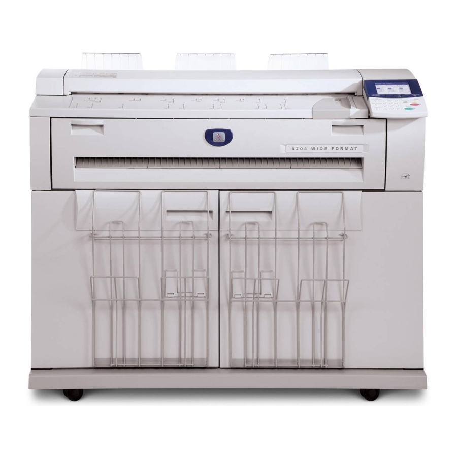
Xerox 6204 Manual
Installation

Condensation may form inside the machine if it is subjected to a sudden change in temperature. When installing the machine in cold weather, allow it to gradually reach room temperature by placing it in a cool environment for approximately one hour. After this, place the machine in a near-room temperature environment for an additional two hours.

To prevent injury to yourself or damage to the machine, unlock the casters before moving the machine. Maintain a firm grip on the machine when it is moving.
- Remove the tape, plastic, bubble wrap, foam pads and boxes. Check the contents of the boxes.
![]()
- Verify that the following required parts and supplies were delivered with the machine:
Xerox 6204 WF- Naturalization Kit x 1
- Power Cord
- Quick Guide
- User Doc CD
- Client Driver CD
- UI Bezel (Upper & Lower)
- Platen Glass Lens & Mirror Cleaner
- Towel
- 36 Inch X 250' Media Roll Document Turn Guide x 3 (MF)
- Toner Cartridge x 2
- R/H Cover x 1
- L/H Cover x 1
- Paper Catch Tray x 2
- Trim Panel x 1
- Naturalization Kit x 1
- Check the machine for any shipping damage.
- Open the Rear Top Cover and Remove the tape and foam pad.

- Remove the tape.
![]()
- Slide the Upper Document Transport forward to the front and lift up to remove it. Remove the foam pads. Clean the platen glass with Xerox Platen Glass Lens and Mirror Cleaner.

- Remove the foam strip from the Upper Document Transport (removed in Fig. 6) and clean the white platen with Xerox Platen Glass Lens and Mirror Cleaner.

- Reinstall the Upper Document Transport.
- Open the Clam Shell and remove the tape and white papers (3 locations). (Fig.8) Also remove the tape and foam from the clam shell latch.

- Remove the sheet with tabs (3x8 mm) inserted in the Photoreceptor and Developer unit. Hold the tabs on both ends of the roll and pull out the long sheet.

- This step positions the Drum Finger against the photoreceptor.
NOTE: Do not move more than 2 cm to avoid the shaft from falling

- Slide the Drum Finger Shaft to the right approximately 2cm.
- Reinsert the shaft into the bottom area slowly.
![]()
Do not touch the surface of the photoreceptor.
- Viewing from the rear of the machine, remove the tape and foam from the Fuser Entrance Baffle.
![]()
- Remove the indicated seals and foam pads in the machine.

- Remove the cushion pads between BTR and the baffle. (Fig.13) Also remove the foam block under the Fuser Nip Lever. (Fig.13a)

- Lift the Transport Baffle and remove the foam pad.
![]()
- Close the Transport Baffle.
- Remove the Waste Toner Bottle. Remove the two screws behind the bottle holding the Fuser Nip Bracket. Rotate the brackest to the position as shown in Figure 15 and reinstall the bracket.
![]()
- Reinstall the Waste Toner Bottle.
- Remove and discard the Edge Guide. Close the ClamShell Unit.
![]()
- Open the Manual Feed Tray and then open the internal cover. Lift up the baffle and remove the foam pads and tape. (Fig. 17) Remove the foam pads and tape from the ends of the Manual Feed Tray.

- Open the Front Door and remove the shipping brackets that hold the drawer in place. Also remove the tape from the drawer latches. Ensure that the drawer moves in and out easily.

- Open the upper drawer and remove the twisted wire and tapes.

- Open the baffle and remove the foam pads and tape.
![]()
Use care when removing tape and pads to prevent damage to the Cutter cable.

- Open the Front Doors and install the trim piece in the lower front of the machine.

- Load one A0/36inch media on Roll1and close the RFC door.
- Install the Print Catch Guides.

- Add 2 packs of the toner cartridge.

NOTE: Shake the toner cartridge well before adding the toner.- Align the notch of the toner cartridge with the right side of the toner supply port.
- Lower the left side of the toner cartridge, and push the toner cartridge into the toner supply port until it clicks.
- Slide the lever to the left, and align it with the triangular symbol.
- Tap the top of the toner cartridge repeatedly until all the toner in the cartridge is loaded (clear bottle).
- Slide the lever to the right, and align it with the triangular symbol.
- Remove the toner cartridge and close the back cover.
- Attach the clear curved Document Turn Guides on scanner exit guide.

- Attach the power cord and fix it in place with a clamp.
![]()
- Check the voltage at the wall socket for the proper voltage. Connect the power plug.
![]()
Ensure that the AC voltage is properly grounded. - Turn on the Circuit Breaker Switch and then the Standby Switch.
- Install the UI Bezels and then enter the diagnostic mode.
- Select IOT and DC131 NVM ACCESS and press ENTER. Select the following to confirm machine type:
- IOT Configuration (NVM 910-001)
US – 1
EO – 2 - IOT Billing Type (NVM 910-002)
0 - Area
1- Length
2 - Area & Length (US) - IOT Billing Units (NVM 910-003)
EO:
0 - Meters
1 - 1/10 Meters
US:
0 – Feet
1 – 1/10 Feet (Not Used)
- IOT Configuration (NVM 910-001)
- Make a sample print using the Print Quality Pattern to verify that the machine prints.
- Update the Controller / Printer firmware if required.
- Perform the Check portion, and then perform the Adjustment portion as necessary for the following adjustment procedures.
NOTE: For those machines that have the optional Roll 2 installed, perform the adjustment on both rolls.- ADJ 9.2 LED Print Head Adjustment
- ADJ 7.1 Cut Length Adjustment for Roll Paper
- ADJ 8.2 Lead Edge Registration Adjustment for Cut Sheet
- ADJ 8.3 Lead Edge Registration Adjustment for Roll Feed
- ADJ 8.1 Side Registration Adjustment
- ADJ 10.1 Fuser Temperature Adjustment
- ADJ 8.4 ITT Magnification Adjustment
- ADJ 9.1 Xerographic Setup
- If the customer has ordered any machine options, install these now.
- Connect the Network Cable.
- Turn off the Main Power Switch and the Circuit Breaker Switch. Attach the covers.
- Switch on the power and enter the diagnostic mode.
- Select IOT and DC606 TEST COPY from the Main Menu.
- Make 3 prints using the following settings and check the print quality
- The number of sheets: 3
- Paper Feed Device: 1
- Media direction: 1
- ROM Pattern Number: 3
- Make 3 scan copies of one of the prints from Step 38 and check the copy quality.
- Perform the Network Setup.
- Load Clients and Drivers.
- Load BT-PA Client Tool and the Windows drivers on one of the customer's PC system.
- Train the customer.


Documents / ResourcesDownload manual
Here you can download full pdf version of manual, it may contain additional safety instructions, warranty information, FCC rules, etc.
Advertisement


Need help?
Do you have a question about the 6204 and is the answer not in the manual?
Questions and answers