Table of Contents
Advertisement
Quick Links
Instruction manual
Instruction manual
Operating & Maintenance
Operating & Maintenance
4812162901_F.pdf
4812162901_F.pdf
Vibratory roller
Vibratory roller
CC4000 VI, CC4200 VI
CC4000 VI, CC4200 VI
CC5200 VI, CC6200 VI
CC5200 VI, CC6200 VI
Cummins QSF 3.8 (Stage IV/T4F)
Cummins QSF 3.8 (Stage IV/T4F)
Cummins F 3.8 (Stage V)
Cummins F 3.8 (Stage V)
Serial number
Serial number
10000401xxA024156 -
10000401xxA024156 -
10000402xxA020192 -
10000402xxA020192 -
10000385xxA018993 -
10000385xxA018993 -
10000403xxA020548 -
10000403xxA020548 -
10000386xxA019539 -
10000386xxA019539 -
10000404xxA019228 -
10000404xxA019228 -
10000387xxA019044 -
10000387xxA019044 -
10000490xxA032400 -
10000490xxA032400 -
10000491xxA0xxxxx -
10000491xxA0xxxxx -
10000496xxA034158 -
10000496xxA034158 -
10000497xxA038688 -
10000497xxA038688 -
10000602xxA037241 -
10000602xxA037241 -
10000603xxA0xxxxx -
10000603xxA0xxxxx -
10000608xxA031751 -
10000608xxA031751 -
Translation of original instruction
Translation of original instruction
Reservation for changes
Reservation for changes
Printed in Sweden
Printed in Sweden
Engine
Engine
Advertisement
Table of Contents

Related Manuals for Fayat CC4000 VI


Summary of Contents for Fayat CC4000 VI
- Page 1 Instruction manual Operating & Maintenance Operating & Maintenance 4812162901_F.pdf 4812162901_F.pdf Vibratory roller Vibratory roller CC4000 VI, CC4200 VI CC4000 VI, CC4200 VI CC5200 VI, CC6200 VI CC5200 VI, CC6200 VI Engine Engine Cummins QSF 3.8 (Stage IV/T4F) Cummins QSF 3.8 (Stage IV/T4F) Cummins F 3.8 (Stage V)
-
Page 3: Table Of Contents
Table of Contents Introduction ..........................1 The machine ....................1 Intended use ....................1 Training ....................... 1 Signal symbols and meaning ..............1 Safety information ..................1 General ....................... 2 CE marking and Declaration of conformity..........3 Safety - General instructions....................5 Safety - when operating ...................... - Page 4 Technical specifications ......................15 Vibrations - Operator station ..............15 Noise level....................15 Electrical system ..................15 Slopes ....................... 15 Dimensions, side view................16 Dimensions, top view ................17 Weights and volumes................18 Working capacity..................19 General ..................... 20 -emission.................... 21 Hydraulic system..................
- Page 5 Decals........................30 Location - decals ..................30 Location - decals, chip spreader (Optional) ..........31 Location - decals, CALIFORNIA ............... 31 Safety decals..................... 31 Info decals....................35 Instruments/Controls ....................36 Control panel and controls ................ 36 Mini-steering wheel, switches (Electronic steering) - Optional....38 Function descriptions ................
- Page 6 AC panel ....................60 ACC - Control panel .................. 60 Main display screen .................. 61 ACC - Operation menus................61 Electrical system...................... 63 Power in engine compartment/battery compartment ........ 63 Main fuse panel..................64 Distribution box ..................64 Circuit board in distribution box..............65 Electricity for Urea system ................
- Page 7 Washer fluid - Checking and filling............77 Starting ........................78 Starting the engine ..................78 Parking brake test ..................79 Display when activating choice via the button set........81 Driving ........................82 Operating the roller ................... 82 Interlock/Emergency stop/Parking brake - Check ........84 Pivotal steering/Offset (Optional) ..............
- Page 8 Short distance towing with the diesel engine switched off/not running ... 104 Towing the roller..................105 Towing eye....................106 Transport ....................... 106 Loading CC4000 VI-CC6200 VI and CO4000 VI-CO6200 VI ................107 Operating instructions - Summary ..................109 Preventive maintenance ...................... 111 Acceptance and delivery inspection............
- Page 9 Every 250/750/1250/1750..hours of operation (Every 3 months)..116 Every 500/1500..hours of operation (Every six months) ..... 117 Every 1000/3000..hours of operation (Each year) ......118 Every 2000/4000..hours of operation (Every two years) ..... 119 Every other year..................119 Maintenance - Every 10h .....................
- Page 10 Air conditioning (Optional) - Cleaning ............. 135 Air conditioning (Optional) - Inspection....................135 Edge cutter (Optional) - Lubrication .................... 135 Maintenance - Every 500h ....................137 Cooler Check - Clean ..................137 Air cleaner Checking - Change the main air filter............138 Backup filter - Change................
- Page 11 Diesel engine Oil change ....................148 Engine Replacing oil filter..................149 The engine fuel filter - replacement/cleaning .......... 149 Drum - oil level Inspection - filling ..................150 Rubber elements and attachment screws Check ...................... 150 Hydraulic filter Change....................151 (1) Hydraulic fluid filter (Main filter) ...........
- Page 12 Drum - oil level Inspection - filling ..................160 Rubber elements and attachment screws Check ...................... 160 Hydraulic reservoir Fluid change.................... 161 Hydraulic filter Change....................162 (1) Hydraulic fluid filter (Main filter) ........... 162 (4) High pressure filter - electronic steering (Optional) ..... 162 Hydraulic reservoir cap - Check ..............
-
Page 13: Introduction
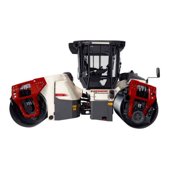
1680/1950/2130 mm (66/77/84 in) wide drums. It features power drive, brakes, vibration and timer controlled water sprinklers on both drums. CC4000 VI, CC4200 VI, CC5200 VI is also available as a Combi-version, with four rubber wheels at the rear instead of steel drums. -
Page 14: General
Introduction We recommend that the operator reads the We recommend that the operator reads the safety instructions in this manual carefully. safety instructions in this manual carefully. Always follow the safety instructions. Ensure Always follow the safety instructions. Ensure that this manual is always easily accessible. that this manual is always easily accessible. -
Page 15: Ce Marking And Declaration Of Conformity
Introduction The machine must be correctly maintained for maximal performance. The machine should be kept clean so that any leakages, loose bolts and loose connections are discovered at as early a point in time as possible. Inspect the machine every day, before starting. Inspect the entire machine so that any leakages or other faults are detected. - Page 16 Introduction 4812162901_F.pdf 2024-03-01...
-
Page 17: Safety - General Instructions
Safety - General instructions Safety - General instructions (Also read the safety manual) • • The operator must be familiar with the contents of the OPERATION section The operator must be familiar with the contents of the OPERATION section before starting the roller. before starting the roller. - Page 18 Safety - General instructions • • Hearing protection is recommended if the noise level exceeds 80 dB(A). The Hearing protection is recommended if the noise level exceeds 80 dB(A). The noise level can vary depending on the equipment on the machine and the noise level can vary depending on the equipment on the machine and the surface the machine is being used on.
-
Page 19: Safety - When Operating
Safety - when operating Safety - when operating Prevent persons from entering or remaining Prevent persons from entering or remaining in the risk zone, i.e. a distance of at least 7 m in the risk zone, i.e. a distance of at least 7 m (23 ft) in all directions from operating machines. -
Page 20: Work Driving
Safety - when operating Work driving The cab has an emergency exit, the right opening The cab has an emergency exit, the right opening windows, which can be crushed with the windows, which can be crushed with the emergency hammer located in the cab. emergency hammer located in the cab. -
Page 21: Safety (Optional)
Safety (Optional) Safety (Optional) Air conditioning The system described in this manual is an AC/ACC type (Automatic climate control) The system contains pressurized refrigerant. It is The system contains pressurized refrigerant. It is forbidden to release refrigerants into the forbidden to release refrigerants into the atmosphere. -
Page 22: Chip Spreader
Safety (Optional) Chip spreader The machine must not be lifted or transported on The machine must not be lifted or transported on another vehicle with chips in the chip spreader. another vehicle with chips in the chip spreader. The weight for the chip spreader is specified on The weight for the chip spreader is specified on the unit rating plate. -
Page 23: Special Instructions
Special instructions Special instructions Standard lubricants and other recommended oils and fluids Before leaving the factory, the systems and components are filled with the oils and fluids specified in the lubricant specification. These are suitable for ambient temperatures in the range -15°C to +40°C (5°F - 105°F). -
Page 24: High Pressure Cleaning
Special instructions High pressure cleaning Do not spray water directly onto electrical components or the instrument panels. The machine has an electric control lever with The machine has an electric control lever with accompanying control unit (ECU), which may not accompanying control unit (ECU), which may not be washed at all with water. -
Page 25: Fire Extinguisher
Special instructions Fire extinguisher A fire extinguisher can be ordered as an option. Though, different standards are used around the world. If not using the original fire extinguisher, place your extinguisher as in the picture. A 4 kg extinguisher is recommended. -
Page 26: Jump Starting (24V)
Special instructions Dispose of old batteries in an environmentally Dispose of old batteries in an environmentally friendly way. Batteries contain toxic lead. friendly way. Batteries contain toxic lead. Do not use a quick-charger for charging the Do not use a quick-charger for charging the battery. -
Page 27: Technical Specifications
Technical specifications Technical specifications Vibrations - Operator station (ISO 2631) The vibration levels are measured in accordance with the operational cycle described in The vibration levels are measured in accordance with the operational cycle described in EU directive 2000/14/EC on machines equipped for the EU market, with vibration switched EU directive 2000/14/EC on machines equipped for the EU market, with vibration switched on, on soft polymer material and with the operator’s seat in the transport position. -
Page 28: Dimensions, Side View
Technical specifications Dimensions, side view Dimensions Dimensions Wheel base Wheel base CC4000 VI CC4000 VI 3680 3680 CC4200 VI, CC5200 VI, CC6200 VI CC4200 VI, CC5200 VI, CC6200 VI 3760 3760 Diameter, drum Diameter, drum CC4000 VI CC4000 VI 1220... -
Page 29: Dimensions, Top View
Technical specifications Dimensions, top view Dimensions Dimensions Machine width, standard Machine width, standard CC4000 VI, CC4200 VI CC4000 VI, CC4200 VI 1910 1910 75.2 75.2 CC5200 VI CC5200 VI 2180 2180 85.8 85.8 CC6200 VI CC6200 VI 2360 2360 92.9 92.9... -
Page 30: Weights And Volumes
14 liters 14 liters 14.8 qts 14.8 qts Water tank/s Water tank/s - central - central CC4000 VI, CC4200 VI CC4000 VI, CC4200 VI No offset No offset 680 liters 680 liters 180 gal 180 gal CC4000 VI, CC4200 VI... -
Page 31: Working Capacity
(CE-2006) (CE-2006) (CE-2006) (CE-2006) CC4000 VI, CC4200 VI CC4000 VI, CC4200 VI 64 (Hz) 64 (Hz) -> s/n 023115 -> s/n 023115 3 060 3 060 3 060 3 060 4 020 4 020... -
Page 32: General
Propulsion Propulsion Speed range Speed range 0-12 km/h 0-12 km/h 0-7.5 mph 0-7.5 mph Climbing capacity (theoretical) Climbing capacity (theoretical) CC4000 VI CC4000 VI 45 % 45 % CC4200 VI CC4200 VI 40 % 40 % CC5200 VI CC5200 VI... -
Page 33: Co 2 -Emission
Technical specifications -emission -emissions measured according to applicable test cycle in Regulation (EU) 2016/1628. Manufacturer/Model Manufacturer/Model Test-cycle Test-cycle -emission -emission (g/kWh) (g/kWh) Cummins F 3.8 Cummins F 3.8 Stage V Stage V NRTC NRTC 717.1 717.1 NRTC: Non-road transient test cycles. NRTC: Non-road transient test cycles. -
Page 34: Air Conditioning / Automatic Climate Control (Acc) (Optional)
Coolant designation: HFC-134a Coolant weight when full: 1.600 kg -equivalent: 2.288 ton GWP:1430 Technical data, Chip spreader (Optional) CC4000 VI, CO4000 VI CC4000 VI, CO4000 VI CC4200 VI, CO4200 VI CC4200 VI, CO4200 VI CC5200 VI, CO5200 VI CC5200 VI, CO5200 VI... -
Page 35: Tightening Torque
Technical specifications Tightening torque Tightening torque in Nm for oiled or dry bolts tightened with a torque wrench. Metric coarse screw thread, bright galvanized (fzb): PROPERTY CLASS: 8.8, Oiled 8.8, Oiled 8.8, Dry 8.8, Dry 10.9, Oiled 10.9, Oiled 10.9, Dry 10.9, Dry 12.9, Oiled 12.9, Oiled... - Page 36 Technical specifications 4812162901_F.pdf 2024-03-01...
-
Page 37: Machine Description
Machine description Machine description Diesel engine The machine is equipped with a water-cooled, straight four cylinder, four-stroke, turbocharged diesel engine with direct injection and a charge air cooler. (Stage IV/Tier 4F) The engine is also equipped with a Cummins® diesel oxidation catalyst and selective catalytic reduction (DOC-SCR) system) for exhaust gas aftertreatment. -
Page 38: Steering System
Machine description Steering system The steering system is a hydrostatic system. The control valve on the steering column distributes the flow to the steering cylinders that affect the articulated joint. A hydraulic pump supplies the control valve with fluid. The steering angle is proportional to the amount the steering wheel is turned. -
Page 39: Fops And Rops
Machine description FOPS and ROPS FOPS is the abbreviation for "Falling Object Protective Structure" (roof protection (ISO 3449)) and ROPS is the abbreviation for "Roll Over Protective Structure" (ISO 3471). If any part of the protective construction on the cab or FOPS/ROPS structure reveals plastic deformation or cracking, the FOPS/ROPS structure must be replaced immediately. -
Page 40: Product Identification Number On The Frame
Machine description Product identification number on the frame The machine PIN (Product Identification Number) (1) is punched on the right edge of the front frame. Fig. PIN Front frame Machine plate The machine type plate (1) is attached to the front left side of the frame, beside the steering joint. -
Page 41: Explanation Of 17Pin Serial Number
Machine description Explanation of 17PIN serial number A= Manufacturer 00123 00123 123456 123456 B= Family/Model C= Check letter F= Serial number Engine plates The engine type plates (1) are affixed to the top and on the right side of the engine. The plates specify the type of engine, serial number and the engine specification. -
Page 42: Decals
Machine description Decals Location - decals 15.16 9.13 17A, 17A, Fig. Location, decals and signs Warning - Crush zone, Warning - Crush zone, 4700903422 4700903422 12. Master switch 12. Master switch 4700904835 4700904835 articulation/drum. articulation/drum. Warning - Rotating engine Warning - Rotating engine 4700903423 4700903423 13. -
Page 43: Location - Decals, Chip Spreader (Optional)
Machine description Location - decals, chip spreader (Optional) Fig. Location, decals and signs Warning, Rotating components Warning, Rotating components 4811000080 4811000080 Location - decals, CALIFORNIA Proposition 65 Warning, CALIFORNIA Warning, CALIFORNIA 4812129673 4812129673 Proposition 65 Proposition 65 1 (Electronic steering) Fig. - Page 44 Machine description 4700903422 Warning - Crush zone, articulation/drum. Maintain a safe distance from the crush zone. (Two crush zones on machines fitted with pivotal steering) 4700903423 Warning - Rotating engine components. Keep your hands at a safe distance. 4700903424 Warning - Hot surfaces in the engine compartment. Keep your hands at a safe distance.
- Page 45 Machine description 4700908229 Warning - Risk of crushing, apply locking device The articulation must be locked when lifting. Read the instruction manual. 4812125363 Warning - Locking during transport The articulation must be locked during transport and lifting, but be open during operation. Read the instruction manual.
- Page 46 Machine description 4812129673 Warning CALIFORNIA - Proposition 65 4812162901_F.pdf 2024-03-01...
-
Page 47: Info Decals
Machine description Info decals Manual compartment Manual compartment Battery voltage Battery voltage Master switch Master switch 4700903425 4700903425 4700393959 4700393959 4700904835 4700904835 Coolant Coolant Water Water Hydraulic fluid level Hydraulic fluid level 4700388449 4700388449 4700991657 4700991657 4700272373 4700272373 Hydraulic fluid Hydraulic fluid Biological hydraulic fluid Biological hydraulic fluid... -
Page 48: Instruments/Controls
Machine description Instruments/Controls Control panel and controls Fig. Control panel Ignition switch Ignition switch Vibration rear drum Vibration rear drum Parking brake Parking brake Forward & Reverse lever Forward & Reverse lever Work mode (Off-set and Work mode (Off-set and vibration permitted plus soft vibration permitted plus soft starting and stopping enabled) - Page 49 Machine description Hazard indicators Hazard indicators Activate the hazard indicators with the switch. Fig. Steering column Functions Functions Direction indicators Direction indicators Driving lights Driving lights Full/Dipped beam Full/Dipped beam Parking lights Parking lights Horn Horn Fig. Steering column switch (optional) 2024-03-01 4812162901_F.pdf...
-
Page 50: Mini-Steering Wheel, Switches (Electronic Steering) - Optional
Machine description Mini-steering wheel, switches (Electronic steering) - Optional Functions Functions Direction indicators Direction indicators Driving lights Driving lights (pos.lights/off /dipped beam) (pos.lights/off /dipped beam) Full beam (off/on) Full beam (off/on) Warning light Warning light Fig. Mini steering wheel with switches Function descriptions Designation Designation... - Page 51 Machine description Designation Designation Symbol Symbol Function Function Button set/Keypad Button set/Keypad Start-stop button Start-stop button Start or stop the diesel engine. Start or stop the diesel engine. Menu button Menu button Menu selector Menu selector Main menu, return Main menu, return Return button to the main menu, "Home."...
-
Page 52: Display Explanations
Machine description Designation Designation Symbol Symbol Function Function Rpm switch, diesel engine Rpm switch, diesel engine Speed adjustment, increases with each press. Selection Speed adjustment, increases with each press. Selection illuminated in the top of the button, idling (-), intermediate illuminated in the top of the button, idling (-), intermediate speed/ECO (- -) and work speed (- - -). - Page 53 Machine description The Home screen shows multiple information images. Fig. Display screen - Home 1. Machine working hours 2. Gear indicator (2 gears) 3. Diesel engine rpm 4. Time watch 5. Fuel level 6. Urea level 7. Sprinkler tank level 8.
- Page 54 Machine description selected front and rear. The display is of "touch screen type" but can also be worked from the display controller. Fig. Display controller The touch screen allows you to activate, adjust different functions etc. directly on the display. If you prefer you can use the display controller instead.
- Page 55 Machine description Asphalt temperature meter Asphalt temperatures are shown either in Celsius or Fahrenheit. (selected in User settings) Fig. Asphalt temperature screen Dual temperature sensors, one front and one rear. The sensor that sits foremost in the current direction of travel is highlighted and it is this one that is read to avoid the disruption of moisture from the drum’s sprinklers.
-
Page 56: Main Menu
Machine description Evib compaction meter (DCM Evib) Compaction meter measures compaction value Evib i MN / m2 Evib acceleration sensor on the front drum. Fig. Compaction meter (DCM) with Evib Min and max values of the Evib value (Evib 1 or Evib 2) on the relevant compaction meter can be adjusted by the plus and minus buttons on the various scales. -
Page 57: User Settings
Machine description "USER SETTINGS" Users can change the light settings, choose between the Metric or Imperial system, and set time and date. User settings Display light Home screen Measure unit Clock Return Date Main menu Settings menu ("SETTINGS MENU") Different selections in the settings menu will bring up areas where settings can be altered for Sprinkler, Settings Motor, Compacting, Seismic, EcoSave, DPF. - Page 58 Machine description SPRINKLER Sprinkler The machine is equipped with two separate sprinkler systems. You can choose to have system 1 activated, alternatively system 2. In exceptional cases, you can choose to have both systems activated, but this results in increased water consumption and more water mist. The sprinklers activation time is always 4 seconds with automatic sprinkling (AWC).
- Page 59 Machine description ENGINE (Stage V) Engine Normally not necessary to use. Regeneration delay only to be used to prevent exhaust gas cleaning when the machine is operating in a hazardous environment, or otherwise inappropriate with the elevated exhaust gas temperature during a regeneration.
-
Page 60: Service Menu
Machine description ECOSave Coming machine feature ECOSave System for automatic shutdown of the diesel engine. DPF (Diesel Particulate Filter) (only for Deutz stage V) Shows DPF status view, more information can be found in Regeneration section under chapter Operation. "SERVICE MENU" The service menu is also accessible via the main menu for adjustments. - Page 61 Machine description "MACHINE STATUS" - Summary of levels, loads and temperatures. "EVIB CALIBRATIONS" Evib Calibrations "SPD LIMIT CALIBRATIONS" Spd Limit Calibrations This section is protected by Pin Code 2024-03-01 4812162901_F.pdf...
- Page 62 Machine description "RAMP SETTINGS" This section is protected by Pin Code Ramp settings There are 3 different modes that can be seleted in the machine's workmode. (Soft, Medium, Hard). The machine alerts at startup when the setting is in Soft Mode. Mode does not change while driving, adjustment of mode selection changes after forward/reverse lever in neutral position.
-
Page 63: Alarm Symbols - Machine
Machine description "ABOUT" It is also possible to see the version of the installed software. About Alarm symbols - Machine The following symbols can be shown at the bottom of the display: Fig. Display - Symbols Symbol Symbol Designation Designation Function Function Warning symbol, hydraulic fluid filter... -
Page 64: Alarm Symbols - Def System And Exhaust Aftertreatment
Machine description Symbol Symbol Designation Designation Function Function Warning symbol, low oil pressure, Warning symbol, low oil pressure, If this symbol is shown, the engine's oil pressure is too low. If this symbol is shown, the engine's oil pressure is too low. diesel engine diesel engine Switch off the engine immediately. -
Page 65: Def-Displays (Urea Tank Level)
Machine description Symbol Symbol Designation and Function Designation and Function Urea qualitet (Yellow) Urea qualitet (Yellow) Appears when urea quality is out of tolerance. Appears when urea quality is out of tolerance. Exhaust cleaning / regeneration symbol. Parked regeneration required (Yellow) (stage V) Exhaust cleaning / regeneration symbol. -
Page 66: Def-Displays (Urea Quality)
Machine description DEF-displays (Urea quality) Symbol Symbol Warning Warning Level Level Comment Comment The warning is shown when the Urea quality in the tank is The warning is shown when the Urea quality in the tank is outside of the tolerance. outside of the tolerance. -
Page 67: Def Displays (Eat - Tampering)
Machine description DEF displays (EAT - Tampering) Symbol Symbol Warning Warning Level Level Comment Comment The warning appears when a fault occurs in the exhaust The warning appears when a fault occurs in the exhaust system’s after-treatment. system’s after-treatment. Immediately contact Service. Immediately contact Service. -
Page 68: Def Displays (Exhaust Cleaning Lamp Disabled (Inhibit) (Stage V)
Machine description DEF displays (Exhaust cleaning lamp disabled (inhibit) (Stage V) Symbol Symbol Warning Warning Level Level Comment Comment The Exhaust System Cleaning/Regeneration Symbol The Exhaust System Cleaning/Regeneration Symbol notifies the operator that the aftertreatment system has not notifies the operator that the aftertreatment system has not auto regenerated at the required time limit and requires an auto regenerated at the required time limit and requires an exhaust system cleaning. -
Page 69: Instruments And Controls, Cab
Machine description Instruments and controls, cab Radio/CD Fig. Cab roof, front Heater Fig. Right rear cab post 15. Hammer for emergency exit 2024-03-01 4812162901_F.pdf... -
Page 70: Function Description Of Instruments And Controls In The Cab
Machine description Function description of instruments and controls in the cab Designation Designation Symbol Symbol Function Function Fuse box Fuse box Contains fuses for the electrical system in the Contains fuses for the electrical system in the cab. cab. Front wiper, switch Front wiper, switch Press to operate the front screen wiper. -
Page 71: Using The Cab Controls
Machine description Using the cab controls. Defroster To quickly remove ice or mist, make sure that only the front and rear air nozzles are open. Turn the heater and fan dial to max. Adjust the nozzle so that it blows on the window to be de-iced, or to remove mist. -
Page 72: Ac Panel
Machine description AC panel Displays figures from 0 to 7. Seven steps to adjust Displays figures from 0 to 7. Seven steps to adjust heating or cooling, and seven steps to adjust fan heating or cooling, and seven steps to adjust fan speed, with 7 as maximum. -
Page 73: Main Display Screen
Machine description Main display screen 1. Air mix control The air mix can be set to full fresh air or full re-circulated air. 2. Mode Displays the mode, "Automatic", "Heat", "Cool" and "Defrost" 3. Temperature Set-point Displays current inside set-point temperature. 4. - Page 74 Machine description AUTO AUTO The system runs automatically to keep the temperature that is The system runs automatically to keep the temperature that is selected (set-point temperature). selected (set-point temperature). Cool Cool A / C compressor is running to cool the interior temperature. A / C compressor is running to cool the interior temperature.
-
Page 75: Electrical System
Machine description Diesel Heat mode (if diesel heater is installed): When a Diesel heat mode signal is received, the backlight will be turned off, the blower will run at 15%, the heater valve will be fully opened and the air circulation will switch to fresh air until the after coil temperature is above 20 º... -
Page 76: Main Fuse Panel
Machine description Main fuse panel The main fuse panel is located behind the left engine compartment door. Fuses by codes: (F4.1) F4.1 F4.1 Main ECU Main ECU (50A) (50A) (F4.2) F4.2 F4.2 Main fuse Main fuse (50A) (50A) (F4.3) F4.3 F4.3 (30A) (30A) -
Page 77: Circuit Board In Distribution Box
Machine description Circuit board in distribution box The figure shows the position of the fuses and the relays. The table below gives fuse amperage and function. All fuses are flat pin fuses, type C (medium). The table also shows the relay functions. Fig. -
Page 78: Electricity For Urea System
Machine description Electricity for Urea system The relays (1 and 2) are located inside the right-hand engine cover in the urea tank compartment. 1. Line heater relay (K36) 2. DEF supply relay (K37) Fig. Cover, right-hand side Fuses in cab The electrical system in the cab has a separate fuse box located behind the cover plate on the front right side of the cab roof. -
Page 79: Operation
Operation Operation Before starting Master switch - Switching on Remember to carry out daily maintenance. Refer to the maintenance instructions. The master switch is located in the engine compartment. Turn the key (1) to the on position. The entire roller is now supplied with power. If the main battery/master switch is covered, the If the main battery/master switch is covered, the engine hood must be unlocked during operation,... -
Page 80: Operator's Seat, Comfort - Adjustments
Operation Operator's seat, comfort - Adjustments Adjust the operator's seat so that the position is comfortable and so that the controls are within easy reach. The seat can be adjusted as follows: - Length adjustment (1) - Height adjustment (2) - Seat-cushion inclination (3) - Backrest inclination (4) - Armrest inclination (5) -
Page 81: Positioning Driver´s Seat (Reversible Driver´s Seat) - Adjustments (Optional)
Operation Positioning driver´s seat (reversible driver´s seat) - Adjustments (Optional) The driver´s seat unit has two adjustments, transverse travel and rotation. Pull the lever (1) forward (A) to release the transverse travel catch for transverse travel. Pull the lever (1) backwards to perform rotation. (B) Find your ideal position. -
Page 82: Belt Reminder
Operation Adjust all settings when the machine is stationary. Adjust all settings when the machine is stationary. Always ensure that the seat is in locked position Always ensure that the seat is in locked position before operating the roller. before operating the roller. Belt reminder The machine can be equipped with seat belt with belt reminder. -
Page 83: Display - Control
Operation Display - Control Sit down for all operations. Turn the ignition key (1) to the right so that a start image is shown on the display. Wait until the start image (2) goes out and the status image is shown on the display. -
Page 84: Interlock
Operation Interlock The roller is equipped with Interlock. If the operator rises from the driver's seat while driving forward/backward, the buzzer sounds and the machine stops after 4 seconds with the diesel engine running. If the control is in neutral when the operator stands up a buzzer will go on until operator is seated or the parking brake is activated. -
Page 85: Operator Position
Operation Operator position If a ROPS (Roll Over Protective Structure) or a cab is fitted to the roller, always wear the seat belt (1) provided and wear a protective helmet. Replace the seat belt (1) if it shows signs of Replace the seat belt (1) if it shows signs of wear or has been subjected to high levels wear or has been subjected to high levels... -
Page 86: View
Operation View Before starting, make sure that the view forwards and backwards is unobstructed. All cab windows should be clean and the rear view mirrors should be correctly adjusted. Fig. View Rear view mirrors - Adjustment The rear view mirror adjustment is accessible from the ground. -
Page 87: Foldable Rotating Beacon (Optional)
Operation Foldable rotating beacon (Optional) Stand firmly with both feet on the top step (1). On a machine equipped with ROPS, hold a firm grip with one hand, on the left rear side rail (2) on the operator platform. Fig. ROPS equipped roller 1. -
Page 88: Working Lights - Adjustment
Operation Now loosen the knob (6) with the other hand and fold down the lamp holder (7). Undo and remove any warning light (8) from the lamp holder. To raise the rotating beacon, perform the above procedure in reverse. The rotating beacon should always be folded down The rotating beacon should always be folded down before transport, where the total height of the before transport, where the total height of the... -
Page 89: Washer Fluid - Checking And Filling
Operation Washer fluid - Checking and filling Place the roller on a level surface. Top up the washer fluid when if necessary, in the reservoir (1) located behind the operator’s seat. The reservoir holds 2.1 liters (2.2 qts) Fig. Operator’s platform 1. -
Page 90: Starting
Operation Starting Starting the engine Make sure that the emergency stop is not activated, but the parking brake is switched on. Set the forward/reverse lever (1) in neutral position. The diesel engine cannot be started in any other position of the lever. Turn the ignition key (2) to the right and a start screen appears on the display. -
Page 91: Parking Brake Test
Operation When starting and driving a machine that is cold, When starting and driving a machine that is cold, remember that the hydraulic fluid is also cold and remember that the hydraulic fluid is also cold and that braking distances can be longer than normal that braking distances can be longer than normal until the machine reaches the working temperature. - Page 92 Operation Wait 2-3 seconds and move the forward/reverse lever (3) slowly forward and slowly back to neutral again and then release the brake test button (5).Be prepared for the machine to move during this operation. Then stop the machine by immediately pulling the lever to neutral If the machine does not move the parking brake effect is approved.
-
Page 93: Display When Activating Choice Via The Button Set
Operation Display when activating choice via the button set. Working mode, offset and vibration possible. Low amplitude/High amplitude Vibration on front and rear drums. Automatic vibration control (AVC active), is selected in "settings-compaction", vibration is activated when the Forward/Reverse lever is outside of neutral. Watering, manual/automatic Automatic water control (auto active), watering is activated when the... -
Page 94: Driving
Operation Driving Operating the roller Under no circumstances is the machine to be Under no circumstances is the machine to be operated from the ground. The operator must be operated from the ground. The operator must be seated inside the machine during all operation. seated inside the machine during all operation. - Page 95 Operation The machine's gear position is shown in the center of the speedometer; select the gear/speed for the task. Fig. The display shows the selection (position 1 or 2) Max. speed Max. speed = Position 1 = Position 1 6 km/h 6 km/h 3.8 mph 3.8 mph...
-
Page 96: Interlock/Emergency Stop/Parking Brake - Check
Operation Interlock/Emergency stop/Parking brake - Check The interlock, emergency stop and parking brake must The interlock, emergency stop and parking brake must be checked daily before operating. A function check of be checked daily before operating. A function check of the interlock and emergency stop requires a restart. -
Page 97: Pivotal Steering/Offset (Optional)
Operation Pivotal steering/Offset (Optional) The machine must be in the Working mode to activate the pivotal steering. Use the two front buttons (1) on the forward/reverse lever to operate the pivotal steering. The pivotal steering control/offset icon (2) is highlighted in yellow when the drums are not aligned. Fig. -
Page 98: Vibration
Operation Vibration Manual/Automatic vibration Activate the button for the Working mode (4). In the manual position the operator has to activate the vibration via the red switch on the forward/reverse lever (2). Automatic vibration control (AVC active), is selected via the display in "settings-compaction", vibration is activated when the Forward/Reverse lever is outside of neutral. -
Page 99: Amplitude/Frequency - Changeover
Operation Amplitude/frequency - Changeover The amplitude setting must not be change when The amplitude setting must not be change when vibration is in operation vibration is in operation Switch the vibration off and wait until vibration Switch the vibration off and wait until vibration stops before changing amplitude. - Page 100 Operation For the Seismic function to deliver maximum performance, it is important that the machine’s IR temperature sensors are kept clean from dirt. Check these regularly and clean the lens, if necessary, with a cotton swab and a mild detergent. Solvent-based detergents should be avoided as they can damage the surface of the lens and affect the sensor’s measuring accuracy.
-
Page 101: Edge Cutting/Pressing (Optional)
Operation Edge cutting/pressing (Optional) The machine must be running to activate the edge cutter/presser. Selection with button (1) for use of the left or right edge cutter/presser and the sprinkler valve for the edge cutter/presser. To avoid asphalt sticking to the edge cutter/presser, a sprinkler system is used for watering. -
Page 102: Chip Spreader (Optional)
Operation Chip spreader (Optional) Activate the button for Working mode (1). Chip spreading is started with the button (2) on the control panel keypad. The button can activate the chip spreader in two ways, Manual or Automatic spreading Left LED, manual spreading, gives continuous spreading. - Page 103 Operation Preparations before adjustment / emptying. The machine should be placed on a level surface The machine should be placed on a level surface with the engine switched off and brake applied. with the engine switched off and brake applied. Emptying Empty the spreader by setting it in transport mode over the required area and by fully opening the lever...
- Page 104 Operation Adjusting the chain 2 Loosen the two nuts, see arrows, for the bearing housing and turn it to the correct position, where the chain has a clearance of approx. 10 mm. Tighten the nuts. Lubrication At the start of every season and after every 40 hours of operation.
- Page 105 Operation Release the eight screws holding the outfeed drum. Lift off the drum and bearing. Unscrew the outfeed rubber. Changing the brushes. Remove the bearings and seals. Remove the old brushes and fit the new brushes. Refit the assembled brush drum in the spreader. Fit the scraper iron and rubber mat.
- Page 106 Operation Preparations before dismantling/assembly. The machine should be standing on a level surface with the engine switched off and the brakes on. Use safe handling equipment to lift the chip Use safe handling equipment to lift the chip spreader off/on. Make sure no-one is in the lifting spreader off/on.
-
Page 107: Braking
Operation 4- Release the hydraulic hoses and cabling. Plug the hoses (dust seals) with the enclosed plugs. 5- Now lift off the container with the requisite lifting device and place on a level surface. Always place a parked container in a safe place Always place a parked container in a safe place away from traffic and marked with reflectors so away from traffic and marked with reflectors so... -
Page 108: Reserve Brake
Operation If the forward/reverse lever is moved quickly (forwards or backwards) toward/past neutral, the system switches to a rapid braking Mode and the machine stops. Activate normal driving Mode again by moving the forward/reverse lever back to neutral. Reserve brake Braking is normally activated using the forward/reverse lever. -
Page 109: Switching Off
Operation Switching off Set the speed control in idling position and allow the engine to idle for a few minutes to cool down. Do not leave the engine idling for too long periods. Do not leave the engine idling for too long periods. Long periods of idling, more than 10 minutes, can Long periods of idling, more than 10 minutes, can cause poor engine performance and, if there is a... -
Page 110: Master Switch
Operation Master switch Before leaving the roller for the day, switch the master switch (1) to the disconnected position and remove the handle. Before switching off the master switch, wait for at Before switching off the master switch, wait for at least 30 seconds after the ignition lock has been least 30 seconds after the ignition lock has been switched off, in order to avoid the engine's... -
Page 111: Long-Term Parking
Long-term parking Long-term parking The following instructions should be followed The following instructions should be followed when long term parking (more than one month). when long term parking (more than one month). These measures apply when parking for a period of up to 6 months. Before re-commissioning the roller, the points marked with an asterisk * must be returned to the pre-storage state. -
Page 112: Steering Cylinders, Hinges, Etc
Long-term parking Steering cylinders, hinges, etc. Grease the steering cylinder pistons with conservation grease. Grease the hinges on the doors to the engine compartment and the cab. Engine coolant Check that the coolant mix are within recommended levels and have a freezing temperature lower than expected lowest temperature during the storage period. -
Page 113: Miscellaneous
Miscellaneous Miscellaneous Lifting Locking the articulation Articulation must be locked to prevent inadvertent Articulation must be locked to prevent inadvertent turning before lifting the roller. turning before lifting the roller. Turn the steering wheel to the straight ahead position. Activate the parking brake. Front frame shall be in line with the rear frame. -
Page 114: Lifting The Roller With Jack
Miscellaneous Lifting the roller with jack: The machine’s gross weight (4) is specified on the The machine’s gross weight (4) is specified on the machine plate (1). machine plate (1). Weight: refer to the machine plate on the The lifting device such as a jack (2), or The lifting device such as a jack (2), or roller equivalent, must be dimensioned according to the... -
Page 115: Towing/Recovering
Miscellaneous Towing/Recovering The roller can be moved up to 300 meters (330 yards) using the instructions below. Short distance towing with the engine running Activate the parking brake, and temporarily stop Activate the parking brake, and temporarily stop the diesel engine. Chock the drums to prevent the the diesel engine. -
Page 116: Short Distance Towing With The Diesel Engine Switched Off/Not Running
Miscellaneous Short distance towing with the diesel engine switched off/not running Chock the drums to prevent the roller from moving Chock the drums to prevent the roller from moving when the brakes are hydraulically disengaged. when the brakes are hydraulically disengaged. Open the left door to the engine compartment to access the propulsion pump. -
Page 117: Towing The Roller
Miscellaneous To leave the bypass position, unscrew the adjusting screw (B) until it stops and then lock the valve again with the hex nut (A). Towing the roller When towing/recovering, the roller must be braked When towing/recovering, the roller must be braked by the towing vehicle. -
Page 118: Towing Eye
Miscellaneous Towing eye The roller may be fitted with an additional towing eye, which must not be used for retrieval (max. permitted pulling force 3000 kg (6 600 lb)). Be sure to follow local traffic rules. Fig. Towing eye Transport Tie-down and secure the machine according to the Cargo Securing Certificate for the specific machine if this is avaliable and applicable. -
Page 119: Loading Cc4000 Vi-Cc6200 Vi And
Miscellaneous Loading CC4000 VI-CC6200 VI and CO4000 VI-CO6200 VI Securing vibratory roller CC4000 VI-CC6200 VI and CO4000 VI-CO6200 VI from Dynapac for transport. (The instructions also apply to Combi machines) Roller loaded in forward direction Alternative Direct of travel 1 - 3 = double lashings, i.e. one lashing with two parts attached to two different lashing points, on 1 - 3 = double lashings, i.e. - Page 120 Miscellaneous Load carrier Load carrier When loaded, the vibratory roller is centered laterally on the platform (± 5 cm). When loaded, the vibratory roller is centered laterally on the platform (± 5 cm). The parking brake is applied and in good working condition, and the articulated joint lock is The parking brake is applied and in good working condition, and the articulated joint lock is closed.
-
Page 121: Operating Instructions - Summary
Operating instructions - Summary Operating instructions - Summary Follow the SAFETY INSTRUCTIONS specified in the Safety Manual. Follow the SAFETY INSTRUCTIONS specified in the Safety Manual. Make sure that all instructions in the MAINTENANCE section int the Instruction Make sure that all instructions in the MAINTENANCE section int the Instruction manual are followed and that the steering hitch lock is unlocked. - Page 122 Operating instructions - Summary When transporting: - Refer to the relevant section in the Instruction Manual. When transporting: - Refer to the relevant section in the Instruction Manual. When recovering - Refer to the relevant section in the Instruction Manual. When recovering - Refer to the relevant section in the Instruction Manual.
-
Page 123: Preventive Maintenance
Preventive maintenance Preventive maintenance Complete maintenance is necessary for the machine to function satisfactorily and at the lowest possible cost. The Maintenance section includes the periodic maintenance that must be carried out on the machine. The recommended maintenance intervals assume that the machine is used in a normal environment and working conditions. - Page 124 Preventive maintenance CALIFORNIA Proposition 65 Decal and location of decal shown in section Machine description. 4812162901_F.pdf 2024-03-01...
-
Page 125: Maintenance - Lubricants And Symbols
Maintenance - Lubricants and symbols Maintenance - Lubricants and symbols Always use high-quality lubricants and the Always use high-quality lubricants and the amounts recommended. Too much grease or amounts recommended. Too much grease or oil can cause overheating, oil can cause overheating, resulting in rapid wear. -
Page 126: Maintenance - Lubricants And Symbols
Maintenance - Lubricants and symbols Fluid volumes Fluid volumes Drum Drum - Drum CC4000 VI - Drum CC4000 VI 13 liters 13 liters 14 qts 14 qts - Drum CC4200 VI - Drum CC4200 VI 14 liters 14 liters 15 qts... -
Page 127: Maintenance - Maintenance Schedule
Maintenance - Maintenance schedule Maintenance - Maintenance schedule General Periodic maintenance should be carried out after the number of hours specified. Use the daily, weekly etc. periods where number of hours cannot be used. Remove all dirt before filling, when checking Remove all dirt before filling, when checking oils and fuel and when lubricating using oil oils and fuel and when lubricating using oil... -
Page 128: After The First 50 Hours Of Operation
Maintenance - Maintenance schedule After the FIRST 50 hours of operation Refer to the contents to find the page number of the sections referred to ! Pos. in Pos. in Action Action Comment Comment Change the hydraulic fluid filter Change the hydraulic fluid filter Refer to 1000h. -
Page 129: Every 500/1500
Maintenance - Maintenance schedule Every 500/1500..hours of operation (Every six months) Refer to the contents to find the page number of the sections referred to ! Pos. in Pos. in Action Action Comment Comment Clean the hydraulic fluid cooler/water cooler Clean the hydraulic fluid cooler/water cooler Or when necessary Or when necessary... -
Page 130: Every 1000/3000
Maintenance - Maintenance schedule Every 1000/3000..hours of operation (Each year) Refer to the contents to find the page number of the sections referred to ! Pos. in Pos. in Action Action Comment Comment Clean the hydraulic fluid cooler/water cooler Clean the hydraulic fluid cooler/water cooler Check the filter element in the air cleaner Check the filter element in the air cleaner... -
Page 131: Every 2000/4000
Maintenance - Maintenance schedule Every 2000/4000..hours of operation (Every two years) Refer to the contents to find the page number of the sections referred to ! Pos. in Pos. in Action Action Comment Comment Clean the hydraulic fluid cooler/water cooler Clean the hydraulic fluid cooler/water cooler Check the filter element in the air cleaner Check the filter element in the air cleaner... - Page 132 Maintenance - Maintenance schedule 4812162901_F.pdf 2024-03-01...
-
Page 133: Maintenance - Every 10H
Maintenance - Every 10h Maintenance - Every 10h Every 10 hours of operation (Daily) Park the roller on a level surface. Park the roller on a level surface. The engine must be switched off and the The engine must be switched off and the parking brake activated when checking or parking brake activated when checking or adjusting the roller, unless otherwise specified. -
Page 134: Coolant Level - Check
Maintenance - Every 10h Coolant level - Check Release the expansion tank hood locks, with the help of the wire with key ring, accessed inside the right-hand engine compartment door. Check that the coolant level is between the max. and min. -
Page 135: Hydraulic Reservoir - Check Fluid Level
Maintenance - Every 10h Hydraulic reservoir - Check fluid level Place the roller on a level surface and check that the oil level in the sight glass (1) is between the max and min markings. If necessary, fill with hydraulic fluid by unscrewing the filler cap (2). -
Page 136: Fuel Tank - Filling
Maintenance - Every 10h Fuel tank - Filling Never refuel while the engine is running. Do not Never refuel while the engine is running. Do not smoke and avoid spilling fuel. smoke and avoid spilling fuel. The fuel tank is located on the front drum frame and the filling is on the right side of the machine. -
Page 137: Water Tank, Std - Filling
Maintenance - Every 10h Water tank, Std - Filling Filler caps are on the front right and left side of the front frame. When quick-filling on a machine with two filling pipes, loosen the filler cap on the nonfilling side to ventilate the water tank. -
Page 138: Sprinkler System/Drum Check
Maintenance - Every 10h Sprinkler system/Drum Check Start the sprinkler system and make sure that none of the nozzles (1) are clogged. If necessary, clean blocked nozzles and the coarse filter placed by the water pump (2). See next section. Figure. -
Page 139: Sprinkler System/Drum Cleaning Of Sprinkler Nozzle
Maintenance - Every 10h Sprinkler system/Drum Cleaning of sprinkler nozzle Dismantle the blocked nozzle by hand. Blow the nozzle (1) and fine filter (3) clean using compressed air. Alternatively, fit replacement parts and clean the blocked parts later on. When working with compressed air, use the When working with compressed air, use the following protective equipment: following protective equipment:... -
Page 140: Scrapers, Spring-Action Check
Maintenance - Every 10h Scrapers, spring-action Check Make sure that the scrapers are undamaged. Release with the arm (1). Loosen the screws (3) to adjust the scraper blade up or down. Fig. Outer scrapers 1. Release arm 2. Scraper blade 3. -
Page 141: Scrapers
Maintenance - Every 10h Scrapers Setting - Adjustment Release the retaining unit (1) for the scraper bracket and unscrew the adjusting screw (2) to release. Push in the scraper bracket and tighten. Adjust the screw (2) so that the scraper blade lies approx. - Page 142 Maintenance - Every 10h 4812162901_F.pdf 2024-03-01...
-
Page 143: Maintenance - Every 50H
Maintenance - Every 50h Maintenance - Every 50h Every 50 hours of operation (Every week) Park the roller on a level surface. Park the roller on a level surface. The engine must be switched off and the The engine must be switched off and the parking brake activated when checking or parking brake activated when checking or adjusting the roller, unless otherwise specified. -
Page 144: Pre-Fuel Filter - Draining
Maintenance - Every 50h Pre-fuel filter - Draining Unscrew the drain plug (1) at the bottom of the fuel prefilter. With the aid of the secondary hand-operated pump, make certain that all sediment comes out. Tighten the drain plug as soon as uncontaminated fuel runs out. -
Page 145: Maintenance - Every 250H
Maintenance - Every 250h Maintenance - Every 250h Every 250/750/1250/1750..hours of operation (every 3 months) Park the roller on a level surface. Park the roller on a level surface. The engine must be switched off and the The engine must be switched off and the parking brake activated when checking or parking brake activated when checking or adjusting the roller, unless otherwise specified. -
Page 146: Battery - Check Condition
Maintenance - Every 250h Battery - Check condition The batteries are sealed and maintenance-free. Make sure there is no open flame in the vicinity Make sure there is no open flame in the vicinity when checking the electrolyte level. Explosive gas when checking the electrolyte level. -
Page 147: Air Conditioning (Optional) - Cleaning
Maintenance - Every 250h Air conditioning (Optional) - Cleaning If there is a significant loss of cooling capacity, clean the condenser element (1). Fig. Rear frame 1. Condenser element Air conditioning (Optional) - Inspection Inspect refrigerant hoses and connections and make sure that there are no signs of an oil film that can indicate a refrigerant leakage. - Page 148 Maintenance - Every 250h 4812162901_F.pdf 2024-03-01...
-
Page 149: Maintenance - Every 500H
Maintenance - Every 500h Maintenance - Every 500h Every 500/1500..hours of operation (every six months) Park the roller on a level surface. Park the roller on a level surface. The engine must be switched off and the The engine must be switched off and the parking brake activated when checking or parking brake activated when checking or adjusting the roller, unless otherwise specified. -
Page 150: Air Cleaner
Maintenance - Every 500h Air cleaner Checking - Change the main air filter Change the air cleaner's main filter when the Change the air cleaner's main filter when the warning lamp on the display lights when the warning lamp on the display lights when the diesel engine is operating at full speed. -
Page 151: Air Cleaner - Cleaning
Maintenance - Every 500h Air cleaner - Cleaning Wipe clean on both sides of the outlet Wipe clean the inside of the cover (2) and the filter pipe. housing (5). See the previous illustration. Wipe also both surfaces for the outlet pipe; see adjacent figure. -
Page 152: Diesel Engine Oil Change
Maintenance - Every 500h Diesel engine Oil change The engine's oil drain plug is located under the rear frame on the machine on the right side.The drain plug is accessed by first removing the rubber plug on the underside of the frame. Observe care when draining hot engine oil. -
Page 153: Engine
Maintenance - Every 500h Engine Replacing oil filter The oil filter (1) is located at the front of the engine and is accessible in the engine compartment inside the right engine door. See the engine manual for information about replacing the filter. -
Page 154: Drum - Oil Level Inspection - Filling
Maintenance - Every 500h Drum - oil level Inspection - filling Position the roller with the filler plug (1), the large plug, at the highest point in its rotation. Wipe clean around the level plug (2), the small plug, and remove the plug. Make sure that the oil level is up to the lower edge of the hole. -
Page 155: Pivot Bearing (Offset) - Lubrication
Maintenance - Every 500h Pivot bearing (OFFSET) - Lubrication Grease each nipple (1) with five strokes of a hand-operated grease gun. Use grease as specified in the lubricant specification. Fig. Front drum, left side 1. Grease nipples, 4 off Seat bearing - Lubrication Keep in mind that the chain is a vital Keep in mind that the chain is a vital part of the steering mechanism. -
Page 156: Edge Cutter (Optional) - Lubrication
Maintenance - Every 500h Edge cutter (Optional) - Lubrication Refer to the operation section for information Refer to the operation section for information on how to operate the edge cutter. on how to operate the edge cutter. Grease the two points as shown in the figure. Grease should always be used for lubrication. -
Page 157: Maintenance - Every 1000H
Maintenance - Every 1000h Maintenance - Every 1000h Every 1000/3000..hours of operation (yearly) Park the roller on a level surface. Park the roller on a level surface. The engine must be switched off and the The engine must be switched off and the parking brake activated when checking or parking brake activated when checking or adjusting the roller, unless otherwise specified. -
Page 158: Air Cleaner
Maintenance - Every 1000h Air cleaner Checking - Change the main air filter Change the air cleaner's main filter when the Change the air cleaner's main filter when the warning lamp on the display lights when the warning lamp on the display lights when the diesel engine is operating at full speed. -
Page 159: Air Cleaner - Cleaning
Maintenance - Every 1000h Air cleaner - Cleaning Wipe clean on both sides of the outlet Wipe clean the inside of the cover (2) and the filter pipe. housing (5). See the previous illustration. Wipe also both surfaces for the outlet pipe; see adjacent figure. -
Page 160: Diesel Engine Oil Change
Maintenance - Every 1000h Diesel engine Oil change The engine's oil drain plug is located under the rear frame on the machine on the right side.The drain plug is accessed by first removing the rubber plug on the underside of the frame. Observe care when draining hot engine oil. -
Page 161: Engine
Maintenance - Every 1000h Engine Replacing oil filter The oil filter (1) is located at the front of the engine and is accessible in the engine compartment inside the right engine door. See the engine manual for information about replacing the filter. -
Page 162: Drum - Oil Level Inspection - Filling
Maintenance - Every 1000h Drum - oil level Inspection - filling Position the roller with the filler plug (1), the large plug, at the highest point in its rotation. Wipe clean around the level plug (2), the small plug, and remove the plug. Make sure that the oil level is up to the lower edge of the hole. -
Page 163: Hydraulic Filter Change
Maintenance - Every 1000h Hydraulic filter Change Filter is accessible from the left side of the machine, in the engine compartment. (1) Hydraulic fluid filter (Main filter) Remove the hydraulic oil filter (1) and deliver to Remove the hydraulic oil filter (1) and deliver to environmentally correct handling. -
Page 164: Hydraulic Reservoir Cap - Check
Maintenance - Every 1000h Hydraulic reservoir cap - Check The cap is accessible from the left side of the machine, in the engine compartment. Unscrew and make sure that the reservoir cap is not clogged. Air must have unobstructed passage through the cap in both directions. -
Page 165: Seat Bearing - Lubrication
Maintenance - Every 1000h Seat bearing - Lubrication Keep in mind that the chain is a vital Keep in mind that the chain is a vital part of the steering mechanism. part of the steering mechanism. Remove the covers (5) to access the lubrication nipple (1). -
Page 166: Air Conditioning (Optional) Fresh Air Filter - Change
Maintenance - Every 1000h Air conditioning (Optional) Fresh air filter - Change Use a step ladder to reach the filter (1). Use a step ladder to reach the filter (1). There is a fresh air filter (1), located at the rear of the cab. Loosen the quick lock (2) and open the protective cover. -
Page 167: Maintenance - Every 2000H
Maintenance - Every 2000h Maintenance - Every 2000h Every 2000/4000..hours of operation (every two years) Park the roller on a level surface. Park the roller on a level surface. The engine must be switched off and the The engine must be switched off and the parking brake activated when checking or parking brake activated when checking or adjusting the roller, unless otherwise specified. -
Page 168: Air Cleaner
Maintenance - Every 2000h Air cleaner Checking - Change the main air filter Change the air cleaner's main filter when the Change the air cleaner's main filter when the warning lamp on the display lights when the warning lamp on the display lights when the diesel engine is operating at full speed. -
Page 169: Air Cleaner - Cleaning
Maintenance - Every 2000h Air cleaner - Cleaning Wipe clean on both sides of the outlet Wipe clean the inside of the cover (2) and the filter pipe. housing (5). See the previous illustration. Wipe also both surfaces for the outlet pipe; see adjacent figure. -
Page 170: Diesel Engine Oil Change
Maintenance - Every 2000h Diesel engine Oil change The engine's oil drain plug is located under the rear frame on the machine on the right side.The drain plug is accessed by first removing the rubber plug on the underside of the frame. Observe care when draining hot engine oil. -
Page 171: Engine
Maintenance - Every 2000h Engine Replacing oil filter The oil filter (1) is located at the front of the engine and is accessible in the engine compartment inside the right engine door. See the engine manual for information about replacing the filter. -
Page 172: Drum - Oil Level Inspection - Filling
Maintenance - Every 2000h Drum - oil level Inspection - filling Position the roller with the filler plug (1), the large plug, at the highest point in its rotation. Wipe clean around the level plug (2), the small plug, and remove the plug. Make sure that the oil level is up to the lower edge of the hole. -
Page 173: Hydraulic Reservoir Fluid Change
Maintenance - Every 2000h Hydraulic reservoir Fluid change Take care when draining the hydraulic fluid. Use Take care when draining the hydraulic fluid. Use the following protective equipment: the following protective equipment: Protective gloves Protective gloves Eye protection Eye protection Drain plug (1) is located under the left-hand side of the rear frame. -
Page 174: Hydraulic Filter Change
Maintenance - Every 2000h Hydraulic filter Change Filter is accessible from the left side of the machine, in the engine compartment. (1) Hydraulic fluid filter (Main filter) Remove the hydraulic oil filter (1) and deliver to Remove the hydraulic oil filter (1) and deliver to environmentally correct handling. -
Page 175: Hydraulic Reservoir Cap - Check
Maintenance - Every 2000h Hydraulic reservoir cap - Check The cap is accessible from the left side of the machine, in the engine compartment. Unscrew and make sure that the reservoir cap is not clogged. Air must have unobstructed passage through the cap in both directions. -
Page 176: Seat Bearing - Lubrication
Maintenance - Every 2000h Seat bearing - Lubrication Keep in mind that the chain is a vital Keep in mind that the chain is a vital part of the steering mechanism. part of the steering mechanism. Remove the covers (5) to access the lubrication nipple (1). -
Page 177: Steering Joint - Check
Maintenance - Every 2000h Steering joint - Check Inspect the steering joint to detect any damage or cracks. Check and tighten any loose bolts. Check also for any stiffness or play in the steering joint. Fig. Steering joint Fuel tank (STD) - Drainage Water and sediment in the fuel tank are drained via a drainage hose. -
Page 178: Fuel Tank (Offset) - Cleaning
Maintenance - Every 2000h Fuel tank (OFFSET) - Cleaning It is easiest to clean the tank when it is almost empty. Drain the tank with a suitable pump, for example, an oil drain pump, to bring up any bottom sediment. Collect the fuel and sediment in a container and Collect the fuel and sediment in a container and deliver to environmentally correct handling. -
Page 179: Watering System - Watering, Rear Tank
Maintenance - Every 2000h Watering system - Watering, rear tank Remember that there is a risk of freezing during Remember that there is a risk of freezing during the winter. Empty the tank, pump, filter and lines, the winter. Empty the tank, pump, filter and lines, or mix antifreeze in the water. -
Page 180: Replacing The Urea Tank Suction Filter
Maintenance - Every 2000h Replacing the urea tank suction filter The urea tank is located on the right-hand side of the machine. For access, the overlying plastic cap (1) and cover plate (2) must be removed. Fig. Guard, right-hand rear frame 1. -
Page 181: Replacing The Urea Pump Filter
Maintenance - Every 2000h Replacing the urea pump filter The urea pump is located on the right-hand side of the machine, in the compartment alongside the urea tank. Release the cover plate and heat guard (2) for access to the urea pump (1), then dismount the filter at the bottom of the unit. -
Page 182: Edge Cutter (Optional) - Lubrication
Maintenance - Every 2000h Edge cutter (Optional) - Lubrication Refer to the operation section for information Refer to the operation section for information on how to operate the edge cutter. on how to operate the edge cutter. Grease the two points as shown in the figure. Grease should always be used for lubrication. -
Page 183: Drying Filter - Check
Maintenance - Every 2000h Drying filter - Check The compressor will be damaged if the unit is run The compressor will be damaged if the unit is run with too little refrigerant. with too little refrigerant. Do not disconnect or undo the hose couplings. Do not disconnect or undo the hose couplings. - Page 184 Dynapac Compaction Equipment AB Box 504, SE 371 23 Karlskrona, Sweden www.dynapac.com...
Need help?
Do you have a question about the CC4000 VI and is the answer not in the manual?
Questions and answers