Table of Contents
Advertisement
Quick Links
Advertisement
Chapters
Table of Contents

Subscribe to Our Youtube Channel
Related Manuals for Fayat DYNAPAC CT3000


Summary of Contents for Fayat DYNAPAC CT3000
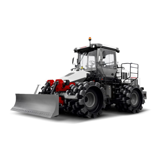
- Page 1 Instructions Manual Operation & Maintenance 4812325559EN Tamping Roller CT3000 Engine Cummins QSB 6.7 ℓ, Tier III and Tier IV From serial number 10000505xxB005408 10000513xxB005408 Reserves the right to introduce modifications Printed in Brazil...
- Page 2 4812325559EN 2018-02-20...
-
Page 3: Table Of Contents
CONTENT OPERATION Page Introduction ..........................1 Safety - General instructions ....................2 Safety-During operation ......................3 Safety - General instructions ....................4 Safety decals – Location and description ................. 5 Technical specifications ......................7 Identification plates ........................8 Operator's instruments and controls..................10 Instruments and controls –... -
Page 5: Introduction
Introduction Introduction Warning symbols ATTENTION! Damage to the machine and its components. CAUTION! Your safety might be involved. Safety manual The operator should read the safety manual that comes with the machine. Always follow the safety instructions and do not remove the manual from the machine. -
Page 6: Safety - General Instructions
Safety – General instructions Safety - General instructions (Read also the Safety Manual) Read and understand this Manual before starting the engine and operating the machine. The operator should be completely familiarized with the machine before usage. Observe and follow all the instructions of lubrication and maintenance contained in the Maintenance Manual. -
Page 7: Safety-During Operation
Safety – Operation Safety-During operation Operation near edges While operating near to edges or holes, make sure that at least half of the tamping rollers are on a compacted ground. Remember that the center of gravity of the machine shifts to the external side when operating the steering wheel. -
Page 8: Safety - General Instructions
Safety – General instructions Safety - General instructions Air conditioning The system contains coolant under pressure. It is forbidden by law to release the coolant into the atmosphere. The maintenance services in the air conditioning system should only be performed by trained personnel with proper equipment and tools. -
Page 9: Safety Decals - Location And Description
Safety decals – Location and description Safety decals – Location and description 2018-02-20 4812325559EN... - Page 10 Safety decals – Location and description WARNING. Zone subjected to WARNING. During Main battery switch. crushing of articulate direction. elevation, block the Keep safe distance from this articulation, read area. instruction manual. WARNING. Be careful! Engine rotating components! Keep your Fuel.
-
Page 11: Technical Specifications
Technical specifications Technical specifications Vibrations – Operator station (ISO 2631) Vibration levels have been measured according to the operational cycle described in the EU directive 2000/14/EC on machines equipped for the EU market with operator seat in transport position. Measured whole-body vibrations are below the action value of 0.5 m/s² as specified in Directive 2002/44/EC. -
Page 12: Identification Plates
Identification plates Identification plates Machine identification plate The identification plate (1) is located on the left side of the machine, in the lower chassis below the fuel tank. This plate indicates the name of the manufacturer and its address, type of machine, serial number and other important information about the product. - Page 13 Identification plates Explanation about the Product Identification 00505 123456 Number (PIN) with 17 characters A – Manufacturer's code (100 = Dynapac) B – Family/model code (00505 or 00513 = CT3000) C – Checking code D – Year of manufacturing (E = 2014, F=2015...) E –...
-
Page 14: Operator's Instruments And Controls
Operator´s instruments and controls Operator's instruments and controls Multifunction display, side control panel and operator's control keyboard 1. Multifunction display 2. Operator's Control Keyboard 3. Warning lights switch 4. Parking brake switch 5. Starter key switch 6. Beacon warning light switch (Optional) 7. - Page 15 Operator's instruments and controls Operator's Control Keyboard 10. Steering turning light 11. Machine warning light – yellow 12. Machine warning light – red 13. High beam 14. Working lights 15. Rear working lights 16. Front working lights 17. Night working lights (Optional) 18.
- Page 16 Operator's instruments and controls Cab instruments Fig. – Rear right column. 4812325559EN 2018-02-20...
-
Page 17: Instruments And Controls - Description And Function
Emergency Procedures Instruments and controls – Description and function Designation Symbol Function Shows the transmission and engine Multifunction display functions. Refer to the "Before Starting the Engine" Section. Operator's Control Keyboard Refer to page 10 Beacon warning light switch Press the switch to light on the beacon warning lights. - Page 18 Emergency Procedures Instruments and controls – Description and function (cont.) Designation Symbol Function Steering turning light Indicates that the steering turning lights are activated. Machine warning light – yellow Indicates that there is failure in the machine. Refer to the multifunction display (1) in order to check the failure.
- Page 19 Emergency Procedures Instruments and controls – Description and function (cont.) Designation Symbol Function Horn button Press to activate the horn. Automatic Climate Control Air conditioning automatic control (see A/C operation for detail). Front wiper, intermittent Intermittent function for front wiper. Front wiper switch Press to operate the front windshield wiper.
- Page 20 Emergency Procedures A/C – System operation Power/Enter By feeding the panel with 24VDC, the screen will be on, indicating that the product is in standby mode. Press to turn on the A/C, it will show the software version and then the temperature.
- Page 21 Emergency Procedures Ventilation The controller has two ventilation modes: manual and automatic ventilation. Manual ventilation The manual ventilation has three speeds. When some function (cooling, heating or automatic mode) is active, the ventilation function is always on. To change the fan speed, press the key (Ventilation mode) and after set the desired speed with the keys After press the key...
- Page 22 Emergency Procedures Multifunction display – General description When the switch is turned to the “I” position, the startup screen is shown on the screen. The screen stays for a couple of seconds and then goes to the status screen. Fig. – Startup screen The status screen shows information about the fuel level, fan speed level, operating hours of the machine and voltage.
- Page 23 Emergency Procedures Multifunction display – General description (cont.) When the selection buttons are pressed a menu field is shown on the screen. The field is shown briefly and then is turned off is no selection is done. A menu field is shown again when one of the selection buttons (1) is pressed.
- Page 24 Emergency Procedures Multifunction display – Alarms DM1 according to SAE J1939 When a transmission or engine alarm is activated, the indication is shown on the screen. The alarm is activated by the engine and transmission controls, which monitor their functions. The message, which shows SPN and FMI codes, can be understood as a relation of failure codes from the engine and transmission suppliers.
- Page 25 Emergency Procedures Multifunction display – Alarms DM1 according to SAE J1939 (cont.) Symbol Description Function There will be necessary to replace the Warning symbol, hydraulic oil filter. hydraulic oil filter if the symbols are shown with the engine in full throttle. There will be necessary to clean the air Warning symbol, air filter.
- Page 26 Emergency Procedures Multifunction display – User settings Press the setting button ( ) so the users can change the lighting settings, choose between the metric or imperial system and define whether there will be sound alarms. NOTA: In every screen, pressing the button returns to the Initial screen.
-
Page 27: Emergency Procedures
Emergency Procedures Emergency procedures Failure on the transmission or engine electric system When the electronic module detects a problem related to the transmission or engine control, the multifunction display will inform the operator through a message with the symbol (2) and the FMI and SPM code (according to DM1 - SAE J1939) of the failure (3), and the machine will be prevented from moving as usual, switching to the emergency movement mode (refer to “Go... - Page 28 Emergency Procedures In the fuses and relay compartment, disconnect the cable 312 (X.10 connector) and connect cable 312 (X.10GT connector) Fig 3 – Cable º312 4. In the transmission module, disconnect the XA9.R1 connector Fig 4 – Connector XA9.R1 NOTE: The procedure above neutralizes the transmissions normal operation and enables the emergency mode.
- Page 29 Emergency Procedures Machine electronic system failure In the occurrence of a machine electronic system failure, the multifunction display will inform the operator through a message with a symbol (2) and the failure code (3), thus indicating the problem. There is no emergency procedure for such cases, therefore, turn off the engine immediately and check the cause.
- Page 30 Regeneration System Regeneration system (Emission Control) After Treatment Screen In this screen you will find urea tank level, warning lamps and engine oil temperature. Make sure that the Urea tank is full during operation. It´s recommended to fill or drain the tank with the system off. If the Urea tank is completely empty you may have error codes related to the after treatment system in the display due to invalid measurements.
- Page 31 Emergency procedures Exhaust System Cleaning Lamps High Exhaust System Temperature (HEST) Lamp May illuminate due to higher-than normal exhaust temperature during Exhaust System Cleaning. Operator should ensure that the exhaust pipe outlet is not directed at any flammable or combustible surfaces. Exhaust System Cleaning Lamp Illuminates when the exhaust system is unable to complete an automatic Exhaust System Cleaning event.
- Page 32 Regeneration System Exhaust System Cleaning Switch Exhaust System Cleaning Enabled The switch remains in the standard mid-position during normal operations. This means Exhaust System Cleaning is enabled and allows the exhaust system to clear any build-up by initiating automatic cleaning. Exhaust System Cleaning...
-
Page 33: Before Starting The Engine
Before starting the engine Before starting the engine Daily maintenance Before starting your shift at work and operating the machine, check that the daily maintenance has been done. Refer to the maintenance section in this manual for other information. Main switch Check if the machine main switch is at the "ON"... - Page 34 Before starting the engine Operator's seat Adjust the operator’s seat in a way that all the controls are easily accessible and the machine operation comfortable. (1) Longitudinal: the adjustment is done through the longitudinal lever (1). (2) Height adjustment: performed through the 1 adjust button.
- Page 35 Before starting the engine Before starting the machine engine Be sure that the parking brake (1) is ON, otherwise turn it on. Turn the engine starter switch (2) to the middle position ("I”). Fig. – Side control panel After the startup screen appears, check if the voltmeter shows at least 24 Volts of voltage, and if the fuel level shows a percentage value compatible with the operation.
- Page 36 Before starting the engine Interlock The machine is equipped with interlock. The diesel engine will shut down after 4 seconds if the operator leaves the seat during the operation. If the parking brake is activated, the diesel engine does not stop. The engine will be shut down automatically if, for any reason, the transmission is not in the neutral position when the operator is not seat in the place.
-
Page 37: Starting The Engine
Starting the engine Starting the engine Starting the engine Check if the emergency starting system (1) is not activated (upper position). Check also if the parking brake is activated (2). Fig. – Side control panel Put the speed lever in the neutral position. The engine will only run with the lever in this position. -
Page 38: Operation
Operation Operation Under no circumstances, the machine should be distanced from the ground. The operator must keep seated on the operator's seat during the operation. Make sure that all areas ahead and behind the machine are free. 1. The selected gear will be the highest one in which the machine will operate. - Page 39 Operation Operation (cont.) 3. Press the acceleration pedal (1). The speed will increase according to the pressure on the pedal. Check that the steering system of the machine is working properly, turning the steering wheel to the left and right with the machine parked. NOTE: Do not change the travel direction when the machine is traveling.
- Page 40 Operation Leveling blade (Optional) The leveling blade should only be used to push, spread or level the material. This blade rests upon the sliding pads to avoid excavation of the compacted layer. NOTE: The blade equipped on the roller is not the dozer kind. Fig.
- Page 41 Operation Tilting blade (Optional) The tilting blade allows the operator to adjust hydraulically the lifting of the blade and carry out inclination and regulation simultaneously. The versatility of the tilting blade gives the machine the capacity of operating in several usages, as in leveling operations, spreading the material, side unloading and “V”...
-
Page 42: Braking
Brakeage Braking Service brake The service brake is activated through the brake pedal (1). The machine has a hydraulic service brake system, with two independent circuits, one for the front axle and one for the rear axle. Fig. – Service brake pedal Parking brake The parking brake and the emergency transmission disc, has a mechanical activation through a spring that is hydraulically... - Page 43 Brakeage Emergency brake The emergency brake and has a mechanical activation through a spring and is hydraulically released, being operated by button (3) located on the side control panel. In case of an emergency the parking brake can be applied as an additional to mobilize the machine. If the machine is traveling forward, as an emergency asset, you can lower the blade to stop the machine.
-
Page 44: Stopping
Brakeage Stopping Stopping the engine 1. Stop the machine positioning the Forward/Backward lever (1) to the neutral position. 2. Release the accelerator pedal (2) and keep the engine working in low idle. Allow the engine to keep working about 3 to 5 minutes. Fig. -
Page 45: Parking
Parking Parking When stopping and parking the machine, always apply the emergency/parking brake. Place, as a safety measure, blocks on the tamping when parking on slopes. Shut off the engine too. To avoid accidents, on slopes or hills, park transversally to the direction of the inclination. Never leave the machine while the engine is operational. -
Page 46: Lifting
Parking Lifting Joint lock Before turning off the machine, lock the chassis joint. Extend the bar (1) and lock it with the pin and its lock (2) to the rear segment of the chassis. Remember to remove the joint lock before using the machine. -
Page 47: Towing
Towing Towing Short distance towing To tow the machine, use the same points used on the lifting process. 1. Park the machine on a safe and leveled ground. Shim the cylinders, if necessary. 2. Install the drawbar (avoid the use of cables and chains). Fig. -
Page 48: Transportation
Towing Transportation Machine transportation 1. Lift the leveling or tilting blade, if equipped. NOTE: If necessary, remove the blade to perform the transportation. 2. Shim the tamping cylinders. 3. Tie the machine on the four fixing spots marked with safety decals. - Page 49 Preparation to use the roller Assembly of the tamping cylinder Identify the front and rear cylinders and note that the front ones have a distance between the rim of the tire and the roller extremities of approximately 9.4" (240 mm), while the rear's distance is of approximately 5"...
- Page 50 Preparation to use the roller Installation of the tamping cylinders (cont.) 1. Remove the bars and scrapers, if installed. 2. Put the machine on proper easels, with a minimum height of 31.5" (800 mm), supporting it on the axles. Lock the front suspension swing yoke properly.
- Page 51 Preparation to use the roller Installing the scrapers M20 BOLTS: The scrapers are provided with the scraping bars, however, they 383.5 lb.ft (520 N.m) (dry) are not initially adjusted. 346.6 lb.ft (470 N.m) (greased) Install the scraping bar and apply the torques according to the following figure: M16 BOLTS: 199.1 lb.ft (270 N.m) (dry)
-
Page 52: General Instructions Of Operation - Summary
General instructions of operation - Summary General instructions operation Summary ● Make sure all the MAINTENANCE INSTRUCTIONS were carried out. For further information, refer to the Maintenance section, in this manual. ● Position the forward/backward lever in the "Neutral" position when the machine is not operating. -
Page 53: Introduction
Maintenance - Symbols and lubricants Introduction Warning symbols ATTENTION! Damage to the machine and its components CAUTION! Your safety might be involved. Safety manual The operator should read the safety manual that comes with the machine. Always follow the safety instructions and do not remove the manual from the machine. -
Page 54: Symbols And Lubricants
Maintenance – Symbols and lubricants Symbols and Lubricants Always use high quality lubricants on the indicated quantity. Excessive grease or lubricant oil can cause overheating and fast wear. ENGINE OIL Room temperature: 14 °F (-10 °C) to 122 °F Shell Rimula 15W40 or equivalent (50 °C) HYDRAULIC FLUID Room temperature: 14 °F (-10 °C) to 104 °F... - Page 55 Maintenance - Symbols and lubricants Engine oil level Engine oil filter Hydraulic fluid level Air filter Brake fluid Hydraulic fluid filter Transmission oil level Fuel filter Battery Coolant level 2018-02-20 4812325559EN...
-
Page 56: Specifications
Maintenance – Specifications Specifications WEIGHT AND DIMENSIONS Operational weight with ROPS 49,251 lbs (22,340 and blade Operational weight with cabin and 49,714 lbs (22,550 blade Length (with the blade) 23.6 ft (7,220 mm) Length (without the blade) 20.3 ft (6,184 mm) Width (with the blade) 11.8 ft (3,598 mm) Width (without the blade) - Page 57 Maintenance - Specifications Specifications (cont.) COMPACTING DATA Cylinder diameter 4.97 ft (1,517 mm) Cylinder width 3.28 ft (1,000 mm) Compacting width (double pass) 14.4 ft (4,410 mm) Pads per cylinder Pads height 0.6 ft (185 mm) Pads contact area 200 cm² Pads distribution model Chevron PERFORMANCE DATA...
- Page 58 Maintenance – Specifications Specifications (cont.) Air conditioning (option) The system described in this manual is the ACC (Automatic Climate Control), that is, a system which maintains the set temperature in the cab provided that all the windows and doors are kept closed. Coolant designation: HFC-R134:A Coolant weight when full: 1,000 g (2.2 lb).
-
Page 59: Lubrication And Maintenance Points
Maintenance - Daily (every 10 hours of operation) Lubrication and maintenance points Read this manual carefully before doing any kind of maintenance service or lubrication operation. Get used to examining the surrounding area around and under the machine. This is an easy way of detecting leaks in their initial stage, as well as anomalies. -
Page 60: Lubrication And Maintenance Procedures
Maintenance – Maintenance and lubrication procedures Lubrication and maintenance procedures Maintenance and lubrication procedures should be made based on the number of operation hours, than subsequently based on the periods, as daily, weekly, etc. Always clean around the caps, grease trays or plugs before opening or applying grease. -
Page 61: Item On
Maintenance – Maintenance and lubrication procedures WEEKLY (Every 50 hours of operation) ITEM ON PROCEDURE PAGE PAG. 52 Check the tire pressure Check the tightening of the wheel bolts Check batteries Lubricate the chassis joint Lubricate the steering system joints Lubricate the longitudinal transmission shaft (axle shaft) Check the condition of the hydraulic hoses and... - Page 62 Maintenance – Maintenance and lubrication procedures MONTHLY (Every 250 hours of operation) ITEM ON PROCEDURE PAGE PAG. 52 Check the conditions and tightening of the bolts and cushion of the cabin or operation platform Check the transmission box oil level Check the front and rear axle oil level Check the parking brake disc and pads Check and clean the radiator...
- Page 63 Maintenance – Maintenance and lubrication procedures ANNUALLY (Every 2,000 hours of operation) ITEM ON PROCEDURE PAGE PAG. 52 Clean the reservoir, replace the hydraulic oil and 5 - 6 the brake and fan drive circuit filters. Replace the engine coolant. Clean and refuel the fuel tank Check the vibration shock absorber of the engine crankshaft...
-
Page 64: Daily (Every 10 Hours Of Operation)
Maintenance – Daily (Every 10 hours of operation) Daily (Every 10 hours of operation) 1. The interlock, emergency stop and parking brake must be checked daily before operating. A function check of the interlock and emergency stop requires a restart. 2. -
Page 65: Check The Brakes
Maintenance – Daily (Every 10 hours of operation) Check the brakes Check the brakeage system in the following manner: 1. Run the machine engine. For further information, please refer to the chapters “Before drive the engine” and “Engine start”, in the Operation section. 2. -
Page 66: Check The Scrapers Adjustment
Maintenance – Daily (Every 10 hours of operation) Check the scrapers adjustment Assure that the scrapers are in good operational condition, otherwise, replace them. If adjustment is needed, follow in the following manner: 1. Release the fixing bolts (1) from the scrapers bar, not completely. -
Page 67: Check The Tire Pressure
Maintenance – Daily (Every 10 hours of operation) Check the tire pressure Tire pressure should be checked when the tires are cold. • Normal pressure: 3.1 bar (45 psi) • Maximum pressure: 4.1 bar (60 psi) – When used for compactation •... -
Page 68: Check The Hydraulic Oil Reservoir Oil Level
Maintenance – Daily (Every 10 hours of operation) Check the hydraulic oil reservoir oil level 1. Park the machine in a leveled ground and shut off the engine. 2. Check the hydraulic oil reservoir (1) located on the left side of the machine, behind the operator's post. -
Page 69: Check The Engine's Coolant Level
Maintenance – Daily (Every 10 hours of operation) Check the engine's coolant level The level of the engine coolant can be visualized through the reservoir translucent walls (1) which are located in the engine compartment, near the radiators. The level should be between the marks “MIN”... -
Page 70: Check The Tension On The Alternator's Belt
Maintenance – Daily (Every 10 hours of operation) Check the tension on the alternator's belt Checking the belt tension should be done with a belt tension meter of tension type or Burroughs type. A new belt should have a tension of 200 lb (890 N). ... -
Page 71: Check The Transmission Box Oil Level
Maintenance – Daily (Every 10 hours of operation) Check the transmission box oil level 1. Turn the steering wheel completely to the right, to allow better access to the level display. Keep personnel away from the chassis joint while executing this operation: risk... -
Page 72: Refuel The Fuel Tank
Maintenance – Daily (Every 10 hours of operation) Refuel the fuel tank Refuel daily with high quality diesel oil up to the beginning of the filler pipe, at the end of a working shift. While filling the fuel, park the machine on a safe and leveled ground, turn the engine off and level the filler nozzle, putting it in contact with the chassis in a non isolated location, before filling... -
Page 73: Check The Exhaust Gases Post-Treatment Connecting
Maintenance – Daily (Every 10 hours of operation) Check exhaust gases post-treatment connecting line (Tier IV Engine) Check leakages, cracking and loose connections in an exhaust line. Check all the line connections, from the turbocharger up to the exhaust line. Be careful with the connecting lines of the Diesel Particulate Filter (DPF), and tight the clamps, if necessary. -
Page 74: Weekly (Every 50 Hours Of Operation)
Maintenance - Weekly (Every 50 hours of operation) Weekly (Every 50 hours of operation) Check the tire pressure Tire pressure should be checked when the tires are cold. • Normal pressure: 3.1 bar (45 psi) • Maximum pressure: 4.1 bar (60 psi) – When used for compactation •... -
Page 75: Check Batteries
Maintenance - Weekly (Every 50 hours of operation) Check batteries Never smoke or allow sparks and flames to be exposed near the batteries while examining them. The batteries usually produce explosive gases, which can cause severe injuries. 1. Open the front cap of the equipment, where the batteries are located. -
Page 76: Lubricate The Chassis Joint
Maintenance - Weekly (Every 50 hours of operation) Lubricate the chassis joint 1. Turn the steering wheel completely to the left to have better access to the grease fittings on the right side of the machine. Keep personnel away from the chassis joint while executing this operation: risk of injuries. -
Page 77: Lubricate The Longitudinal Transmission Shaft
Maintenance - Weekly (Every 50 hours of operation) Lubricate the longitudinal transmission shaft (axle shaft) 1. Lubricate each grease fitting with the manual cycles of the grease recommended by DYNAPAC. Use only grease recommended by DYNAPAC. Fig. – Longitudinal transmission shaft 2. -
Page 78: Replace The Hydraulic Oil Filters
Maintenance - Weekly (Every 50 hours of operation) Replace the hydraulic oil filters (ONLY ON THE FIRST 50 HOURS) 1. Open the reservoir cap to relief any kind of pressure inside it. 2. Verify if the filter breath of the cap is not clogged and clean it, if necessary. -
Page 79: Biweekly (Every 100 Hours Of Operation)
Maintenance - Biweekly (Every 100 hours of operation) Biweekly (Every 100 hours of operation) Replace the front and rear axle oil (ONLY ON THE FIRST 100 HOURS) This oil replacement should be done only with 100 hours of operation. The other ones should be done every 1,500 hours. -
Page 80: Verify The Torque In The Screws Of Chassis Joint
Maintenance - Biweekly (Every 100 hours of operation) 6. Run the engine at low idle and with the transmission warmed up at 176 F (80 °C), check the oil level on the display and refill if necessary (refer to the procedure “Check the transmission box oil level”, in this section). -
Page 81: Monthly (Every 250 Hours Of Operation)
Maintenance - Monthly (Every 250 hours of operation) Monthly (Every 250 hours of operation) Check the conditions and tightening of the bolts and cushion of the cabin or operation platform 1. Carry out a visual inspection of the cushions, brackets and dampers of the cabin or the operation platform. -
Page 82: Check The Front And Rear Axle Oil Level
Maintenance – Monthly (Every 250 hours of operation) Check the front and rear axle oil level Never perform maintenance under the machine when the engine is running. Always park the machine on a leveled ground and shim the cylinders. 1. Make sure that the machine is on a leveled ground and the parking brake is applied. -
Page 83: Check And Clean The Radiator
Maintenance - Monthly (Every 250 hours of operation) Check and clean the radiator 1. Make sure that the air flow is freely passing through the radiators, without any obstructions. In case the hives are dirty, wash them with running water (with the engine off) and clean them with pressurized air. - Page 84 Maintenance – Monthly (Every 250 hours of operation) Replace the lubricant oil and the engine oil filter (cont.) 1. Clean the area around the engine base of the oil filter. 2. Remove the filter element (3) with a belt wrench and discard 3.
-
Page 85: Replace The Fuel Filters
Maintenance - Monthly (Every 250 hours of operation) Replace the fuel filters 1. Clean the area around the bases of the fuel pre-filter and main filter. 2. Remove the pre-filter (1) and main filter (2) elements with a belt wrench and discard them properly. NOTE :The pre-filter has a black stripe indicating when it should be replaced. -
Page 86: Quarterly (Every 500 Hours Of Operation)
Maintenance – Monthly (Every 250 hours of operation) Quarterly (Every 500 hours of operation) Replace the air filter main element 1. Release the clamps and remove the cap (1). 2. Remove the main element from the air filter casing, pulling it out. -
Page 87: Biannually (Every 1,000 Hours Of Operation)
Maintenance - By-annually (Every 1,000 hours of operation) Bi annually (Every 1,000 hours of operation) Check the condition of the hydraulic hoses and connections Verify if the hydraulic system hoses and connections are loose, cracked or damaged, and if so, replace them. Also check the seal rings and clamps. -
Page 88: Replace The Hydraulic Oil Filters
Maintenance – By-annually (Every 1,000 hours of operation) Replace the hydraulic oil filters 1. Open the reservoir cap (1) to relief any kind of pressure inside it. 2. Verify if the filter breath of the cap is not clogged and clean it, if necessary. -
Page 89: Drain The Condensed Water From The Hydraulic Oil
Maintenance - By-annually (Every 1,000 hours of operation) Drain the condensed water from the hydraulic oil reservoir 1. Place a proper container under the drainage plug of the reservoir. 2. Open the drainage plug and only allow the water to drain from the reservoir. -
Page 90: Replace The Transmission Box Oil
Maintenance – By-annually (Every 1,000 hours of operation) Replace the transmission box oil 1. Turn the steering wheel completely to the right, to allow better access to the level display. NOTE: Make sure that the machine is on a leveled ground and the parking brake is applied. - Page 91 Maintenance – By-annually (Every 1,000 hours of operation) Replace the transmission box oil (cont.) Use only oil recommended by DYNAPAC. 11. Run the engine and keep it at low idle until it fills the lines and feeds the torque converter (approximately 8 minutes). 12.
-
Page 92: Replace The Air Filter Safety Element
Maintenance – By-annually (Every 1,000 hours of operation) Replace the air filter safety element The air filter is located on the right side of the engine compartment. Release the clamps and remove the cap. Remove the main element from the air filter casing, pulling it out. -
Page 93: Drain The Sediment Water From The Fuel Tank
Maintenance – By-annually (Every 1,000 hours of operation) Drain the sediment water from the fuel tank NEVER perform maintenance under the machine when the engine is running. Always park the machine on a leveled ground and shim the cylinders. Place a proper container under the drainage plug of the fuel tank (1). -
Page 94: Replace The Front And Rear Axle Oil
Maintenance – By-annually (Every 1,000 hours of operation) Replace the front and rear axle oil (initial) This oil replacement should be done only with 100 hours of operation. The other ones should be done every 1,000 hours. Never perform maintenance under the machine when the engine is running. -
Page 95: Annually (Every 2,000 Hours Of Operation)
Maintenance - Annually (Every 2,000 hours of operation) Annually (Every 2,000 hours of operation) Clean the reservoir and replace the hydraulic oil and filters 1. Park the machine in a leveled ground and shut off the engine. 2. Provide a container capable of draining the hydraulic circuit reservoir. -
Page 96: Replace The Engine Coolant
Maintenance – Annually (Every 2,000 hours of operation) Replace the engine coolant. Caution! Risk of severe burns! Wait until the engine's temperature is below 122 °F (50 °C) before removing the cap of the coolant reservoir or draining the cooling system. 1. -
Page 97: Clean And Refuel The Fuel Tank
Maintenance - Annually (Every 2,000 hours of operation) Clean and refuel the fuel tank NEVER perform maintenance under the machine when the engine is running. Always park the machine on a leveled ground and shim the cylinders. 1. Open the fuel tank cap. 2. -
Page 98: Long Lasting Intervals
Maintenance – Annually (Every 2,000 hours of operation) Long lasting intervals The following instructions should be noticed if there is the intention of keeping the machine parked over a month without any usage. Fig. – Tamping roller protected against wear and tear. These parameters are applied to long lasting intervals up to six months. -
Page 99: Special Instructions
Maintenance – Special instructions Special instructions Recommended When the machine leaves the factory, it is fueled with standard fluids and the recommended fluids and oils indicated in the item “Symbols and lubricants”, which are the proper ones for operating in environments with temperatures between 14 °F (-10 °C) - + 104 °F (40 °C). - Page 100 Maintenance – Special instructions In order to prevent damage on the electronic modules, it is necessary to perform the welding correctly. Whenever possible, remove the component to be welded from the machine or engine, and only after that carry out the operation/maintenance. If it is necessary to perform the welding next to one of the engine or machine electronic modules, remove it for a while, to prevent possible damage due the heat or electric discharge.
- Page 101 Maintenance – Special instructions Hydraulic System Pressure Values The machine has 8 pressure measurement points, and maintenance and verification can be performed through them: 2 / 3 / 4 / 5 POINT 1 – Steering system pressure measurement point It is located on the front chassis, at the left side, next to the joint.
- Page 102 Maintenance – Special instructions POINT 2 – Fan drive pressure measurement point. It is located on the rear chassis, at the right side, on the engine's cap (1 point from the rear to the front part). Measurement pressure: 100 bar (1,450 psi) with the fan working at 2,200 RPM.(to realize measurement press the Engine radiators assembly cleaning button Fig.
- Page 103 Maintenance – Special instructions POINT 7 – Rear brake measurement point. It is located on the rear chassis, at the right side, next to the joint and transmission. Measurement pressure: Maximum of 40 bar (580 psi). Fig. – Measurement point 7 POINT 8 –...
-
Page 104: Electrical System
Maintenance – Electrical system Electrical system The fuse and relay box is located on the left side of the machine, right under the operation post. The machine is equipped with a 12 V electrical system, supplied by a 95 A alternator powered by two batteries. Connect the batteries on their correct polarity (negative terminals to the mass). - Page 105 Maintenance – Electrical system Cabin fuse box It is located on the cabin roof, above the switch panel. 1. Inner Illumination (10A) 2. CD/Radio (10A) 3. Air Conditioning (15A) 4. Heating system (10A) 5. Front windshield washer and wiper (10A) 6.
- Page 106 Maintenance – Electrical system Electronic modules The electronic modules are located on the engine compartment, at the left side of the machine, and can be accessed by opening the cap with a belt wrench. Fig. – Electronic modules compartment The engine electronic module (1) is located on its right side, next to the diagnostic connector - DLC (2).
- Page 107 2018-02-20 4812325559EN...
- Page 108 Dynapac do Brasil Industria e Comercio de Maquinas Ltda. Rua Georg Schaeffler, 430, Sorocaba/SP, Brasil Tel.: +55 (15) 3412-7500 Fax.: +55 (15) 3412-7522 www.dynapac.com...
Need help?
Do you have a question about the DYNAPAC CT3000 and is the answer not in the manual?
Questions and answers