Table of Contents
Advertisement
Quick Links
Advertisement
Table of Contents
Troubleshooting

Related Manuals for Fayat Dynapac F80W


Summary of Contents for Fayat Dynapac F80W
- Page 1 OPERATING MANUAL Asphalt paver wheeled F80W Hatz 4812217930...
- Page 3 F80W Asphalt paver, wheeled Hatz Tier 4 final Operating Manual Edition 04/2018 EN From Serial No. 4510023 Original Operating Manual...
- Page 7 Congratulations to purchasing a new DYNAPAC machine. This modern machine is characterised by simple operation and easy mainte- nance. In order to avoid faults due to improper operation and maintenance, we request that you read this Operating Manual with great care and keep them for later reference. With kind regards, Dynapac GmbH | Ammerlaender Str.
- Page 8 Preface Information, specifications, and recommended operation and maintenance instructions contained in this publication are basic and final information at the time of the printing of this publication. Printer’s errors, technical modifications, and modifications of figures are reserved. All dimensions and weights are approximate and, therefore, not binding. DYNAPAC reserves the right to perform modifications at any time with no obligation to inform the machine user.
- Page 9 SAFETY NOTICES AND SIGNS: The notice warns of a serious risk of personal injury or other personal hazards. The notice warns of possible damage to the machine or its parts. The notice warns of the necessity of environmental protection. ! CAUTION! As used in this operating manual, the terms right, left, front and rear indicate sides of the machine moving forward.
-
Page 10: Table Of Contents
Contents Contents ................................4 SPECIFICATION MANUAL ........................9 1.1 Basic data ..............................10 1.2 Dimensional drawing of the machine ....................12 1.3 Technical data ............................14 1.3.1 Specification table .........................................14 1.3.2 Machine gradeability and lateral static stability ............................16 1.4 Optional equipment ..........................18 1.4.1 Table of optional equipment .....................................18 1.4.2 Screed vibration units ......................................19 1.4.3... - Page 11 OPERATING MANUAL 2.3 Machine disposal ..........................57 2.3.1 Machine disposal after its service life ................................57 2.4 Machine description ..........................58 2.4.1 Description of main parts of the machine and screed ..........................59 2.4.2 Main dashboard ........................................62 2.4.3 Display ............................................66 2.4.4 Foot switch ..........................................68 2.5 Operation of the machine ........................70 2.5.1 Turning ON/OFF the battery disconnecter ..............................70...
- Page 12 Contents MAINTENANCE MANUAL ........................119 3.1 Safety and other measures during maintenance of the machine ..........121 3.1.1 Safety precautions during machine maintenance ..........................121 3.1.2 Safety and fire precautions during replacement of operating fluids ....................122 3.1.3 Environmental and hygienic principles ..............................123 3.1.3.1 Hygienic principles ......................................
- Page 13 OPERATING MANUAL Every 100 hours of operation (monthly) ...................150 3.6.14 Fuel system tightness check ................................... 150 3.6.15 Rear wheel fastening check .................................... 151 3.6.16 Conveyor chain tensioning ..................................... 152 Every 250 hours of operation (every 3 months) ................153 3.6.17 Engine oil replacement ..................................... 153 3.6.18 Engine air intake check .....................................
- Page 14 F80W...
-
Page 15: Specification Manual
SPECIFICATION MANUAL 1 SPECIFICATION MANUAL F80W (Hatz Tier 4 Final) F80W... -
Page 16: Basic Data
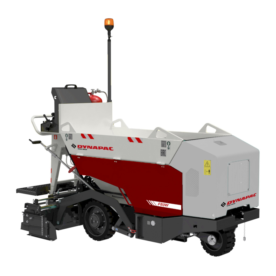
Basic data Machine description Machine type The F80W wheeled asphalt paver is equipped with a screed with gas heating. The basic paving width is from 800 mm (31.5 in) to ........................ 1,300 mm (51.2 in). Serial number of the machine The machine is characterised with good manoeuvrability, good view from the operator's place, a wide range of uses and easy transport. - Page 17 SPECIFICATION MANUAL Nameplate. Serial number of the machine. AMMERLAENDER STR. 93 D-26203 WARDENBURG GERMANY D451023 Serial number of the engine. D451024 Nameplate of the screed. Serial number of the screed. D451025 F80W...
-
Page 18: Dimensional Drawing Of The Machine
Dimensional drawing of the machine D451170A F80W... - Page 19 SPECIFICATION MANUAL 1280 2070 2680 1598 2865 2526 50,4 81,5 105,5 62,9 112,8 99,4 2550 1150 1699 100,4 30,1 25,2 31,5 45,3 66,9 F80W...
-
Page 20: Technical Data
Technical data 1.3.1 Specification table Weight The machine operation weight (including: screed extension, doubled driving wheels, vibration) kg (lb) 1260 (2780) Transport weight kg (lb) 1,185 (2,610) Driving characteristics Number of speeds Operating speed km/h (MPH) 0.6 (0.37) Transport speed km/h (MPH) 2.5 (1.6) Machine gradeability with an empty hopper (screed in the lower position) - Page 21 SPECIFICATION MANUAL Operating fluids Fuel l (gal US) 5 (1.3) Engine (oil filling) l (gal US) 1.8 (0.5) Hydraulic system l (gal US) 20 (5.3) Lubricants kg (lb) 0.1 (0.22) Gas bottle with the maximum volume kg (lb) 10 (22) Maximum operating pressure Recommended operating pressure 0.6–0.8...
-
Page 22: Machine Gradeability And Lateral Static Stability
1.3. Technical data 1.3.2 Machine gradeability and lateral static stability Machine gradeability with an empty hopper (screed in the lower position). α = 7° (12%) D451171 Machine gradeability with a full hopper (screed in the lower po- sition). α = 11° (19%) D451172 Machine descent with an empty hopper (screed in the lower position). - Page 23 SPECIFICATION MANUAL Lateral static stability with an empty and full hopper. α = 12° (21%) D451175 F80W...
-
Page 24: Optional Equipment
Optional equipment 1.4.1 Table of optional equipment Chapter Optional equipment Order number 1.4.2 Screed vibration units 4812061026 1.4.3 Mechanical screed extension 4812061017 1.4.4 Dual wheels 4812061018 1.4.5 Front wheel scraper 4812061021 1.4.6 Material hopper extension 4812061019 1.4.7 Additional lighting 4812061020 F80W... -
Page 25: Screed Vibration Units
SPECIFICATION MANUAL 1.4.2 Screed vibration units The function of the screed vibration serves for reducing a ma- chine travel resistance during paving and improving the surface of the paved asphalt mixture. Mount the screed vibration units according to the Mounting Manual. D451811 Screed vibration units kit Order no.: 4812061026... -
Page 26: Mechanical Screed Extension
Optional equipment 1.4.3 Mechanical screed extension The mechanical screed extension serves for extending the pav- ing width. The maximum width of the screed is 1,300 mm. After install- ing the mechanical screed extension set, the maximum screed width will increase by 350 mm to 1,650 mm. Paving width with mechanical extension is: •... - Page 27 SPECIFICATION MANUAL Setting the paving width Procedure for setting the required paving width on the left side of the screed: To increase the paving width on the left side, turn the paving width switch (2) to the left and hold it. To release the paving width switch (2), lock it back to the middle position and the screed stops in the required position.
-
Page 28: Dual Wheels
Optional equipment 1.4.4 Dual wheels Dual wheels serve for the improvement of machine traction and stability. A dual wheel, which is part of the dual wheel set, is identical with the standard rear wheel. Distance between external surfaces of rear wheels: •... -
Page 29: Front Wheel Scraper
SPECIFICATION MANUAL 1.4.5 Front wheel scraper The scraper (1) is located on the swing fork of the front wheel and serves for cleaning the front wheel from gross dirt. Mount the scraper according to the Mounting Manual. Front wheel scraper kit 451817 Order no.: 4812061021 The front wheel scraper kit consists of the following com-... -
Page 30: Material Hopper Extension
Optional equipment 1.4.6 Material hopper extension The material hopper extension serves for enlarging the filling space and easier feeding of material to the machine. The material hopper extension consists of two plates (1) and (2), which are fitted with two fork-shaped holders (3) Mount the material hopper extensions according to the Mounting Manual. -
Page 31: Additional Lighting
SPECIFICATION MANUAL 1.4.7 Additional lighting Additional lighting (1) serves for lighting the area of the screed and augers. Mount the additional lighting according to the Mounting Manual. Additional lighting kit D45181 Order number: 4812061020 The additional lighting kit consists of the following compo- nents: •... - Page 32 Notes F80W...
- Page 33 SPECIFICATION MANUAL Notes F80W...
- Page 34 F80W...
-
Page 35: Operating Manual
OPERATING MANUAL 2 OPERATING MANUAL F80W (Hatz Tier 4 Final) F80W... -
Page 36: Main Safety Precautions
Main safety precautions 2.1.1 Obligations before putting into 2.1.2 Assurance of safety precautions by the operation owner Before starting working with the machine, the machine opera- He must ensure that the machine is operated only under con- tor and the machine operator shall read this Operating Manual ditions and only for purposes it is technically capable for ac- and make themselves familiar with the operation of the ma- cording to conditions set by the manufacturer and respective... -
Page 37: Requirements For Qualified Personnel
OPERATING MANUAL 2.1.3 Requirements for qualified personnel All activities on the machine may only be performed by qualified, instructed and trained personnel. Qualified, instructed and trained personnel shall: • be over 18 years old, • trained in the provision of first aid and be able to provide it, •... -
Page 38: Machine Operator's Obligations
Main safety precautions 2.1.4 Machine operator's obligations Before starting operation of the machine, the driver is obliged After a warning alarm, the operator may put the machine into to get familiar with instructions stated in the documentation operation only when all workers have left the endangered area supplied together with the machine, especially with safety pre- and are at a safe distance from the machine. -
Page 39: Screed Operators' Obligations
OPERATING MANUAL 2.1.5 Screed operators' obligations Before starting operation of the machine, screed operators are The operator must carry out the machine maintenance in com- obliged to get familiar with instructions stated in the documen- pliance with instructions specified in the Operating manual. tation supplied together with the machine, especially with safe- The screed operator is obliged to equip the machine with acces- ty precautions, and strictly observe the instructions. -
Page 40: Driver's Stand And Screed Operator Stand During Machine Operation
Main safety precautions 2.1.6 Driver's stand and screed operator stand during machine operation These requirements during operation of the machine are considered binding with regard to the safety of people. Firstly, the machine operator and the screed operators must observe the below-given requirements during ma- chine operation. -
Page 41: Dangerous Zone And Safe Distance
OPERATING MANUAL 2.1.7 Dangerous zone and safe distance D451028 Dangerous zone of the machine: During the operation of the machine and paving no people may be present and stay in the dangerous zone of the machine. The dangerous zone of the machine (1) may only be entered into for the purpose of maintenance and cleaning of the machine when the conditions below are met: •... - Page 42 Main safety precautions Safe distance between a public road, the place of paving and the construction site: The safe distance between a public road, the place of paving and the construction site must be marked with a visible barrier against unauthorised access of other people to the place of paving and construction site. The safe distance between a public road, the place of paving and the construction site is determined by the machine user on the basis of respective national regulations.
- Page 43 OPERATING MANUAL Safe distance of workers at the place of paving: All workers present at the place of paving, moving near the machine, but not directly operating the machine, must observe the mini- mum safe distance of 5 metres from the machine. The machine user as well as the machine operator must ensure adherence to the aforementioned safe distance of 5 m from the machine with regard to safety of workers at the place of paving.
-
Page 44: Machine Operation At Unclear Working Areas
Main safety precautions 2.1.8 Machine operation at unclear working areas The machine operator may not operate the machine if he does not have a sufficient overview of the workplace and potential obstacles are not clearly visible. In such cases, a different efficient form of connection between the appointed worker and the machine operator must be ensured. - Page 45 OPERATING MANUAL EXAMPLES OF HAND SIGNALS: Start the engine 0040 Turn off the engine 0041 Stop STOP 0031 Watch out 0032 F80W...
- Page 46 Main safety precautions Watch out, danger 0033 Machine travel 0034 Drive slowly forward – towards me 0035 Drive slowly backward – away from me 0036 F80W...
- Page 47 OPERATING MANUAL Machine travel – to the right 0037 Machine travel – to the left 0038 Machine travel for a short distance 0039 F80W...
-
Page 48: Safety Notices And Symbols Used On The Machine
Main safety precautions 2.1.10 Safety notices and symbols used on the machine 14 15 D451034B F80W... - Page 49 OPERATING MANUAL Keep a safe distance! Danger zone 2939 2942bz Keep a safe distance! Danger of injury due to augers. 0045 There is a risk of electric shock. Risk of injury and electric shock. 0019 Get perfectly familiar with the machine operation and Read the operating maintenance according to the Operating Manual! manual...
- Page 50 Main safety precautions Dangerous noise level! Use hearing protection. Hearing protection 2408bz Hydraulic oil level 2158 Indication of the paving thickness. Paving thickness scale 1259532 Indication of the speed controller for engine speed adjustment. Speed controller position 2406 Only use these points to lift the machine. Lifting hole 2153bz Tie-down the machine for transport at these points only.
-
Page 51: Personal Protective Equipment
OPERATING MANUAL 2.1.11 Personal protective equipment The machine operator, technical administrators, service technicians and workers present at the workplace must use personal protec- tive equipment during operation and maintenance of the machine: Wear work clothes (antistatic protective clothes). 0001 Wear work shoes (antistatic protective shoes). 0008 Wear a warning vest. -
Page 52: General Safety Precautions
Main safety precautions 2.1.12 General safety precautions 2.1.13 Safety precautions during machine operation Always use personal protective equipment such as work clothes, work shoes, a warning vest, a protective helmet, hearing protec- Before using the machine or its equipment, make sure that no- tion and if necessary also a dust protection mask, safety glasses body is present in the dangerous zone of the machine. -
Page 53: Safety And Fire Precautions During The Use Of Gas Bottles
OPERATING MANUAL 2.1.14 Safety and fire precautions during the use of gas bottles The machine user must ensure and hand over to respective au- thorised workers any and all information for the safe use and Propane-butane (LPG) is an extremely flammable substance handling of gas bottles if they form part of the equipment dur- and any leakage causes a high risk of fire or explosion! ing the operation of the machine always in compliance with re-... -
Page 54: Safety Precautions For The Use Of Portable Fire Extinguisher
Main safety precautions 2.1.15 Safety precautions for the use of 2.1.16 Safety and fire precautions during portable fire extinguisher welding on the machine A portable fire extinguisher must comply with requirements of The machine user shall ensure that all welding works on the ma- EN 3-7+A1. -
Page 55: Safety Precautions For Electrical And Electronic Equipment Of The Machine
OPERATING MANUAL 2.1.17 Safety precautions for electrical and Safety precautions electronic equipment of the machine Electrical installations and wiring must be connected properly and according to data given in this Operating Manual. • The machine is equipped with electrical wiring, components Entire electrical wiring and connection components must be and electronic equipment, the operation of which can be in- have adequate current rating within the meaning of valid regu-... -
Page 56: Prohibited Activities
Main safety precautions 2.1.18 Prohibited activities Prohibited activities during machine control: • The machine operator must not operate the machine with- This chapter deals with main prohibited activities during opera- out personal protective equipment. tion, work, repairs and maintenance of the machine. •... - Page 57 OPERATING MANUAL Prohibited activities during machine operation: Prohibited activities during repairs and maintenance of the machine: • Operating the machine without personal protective equip- ment. • Performing maintenance, cleaning and repairs without per- sonal protective equipment. • Operating the machine if any defects are found, if the ma- chine is not serviceable and if all safety conditions for ma- •...
-
Page 58: Preservation And Storage
Preservation and storage 2.2.1 Storage places and storage conditions The machine can be stored under a shelter or in an open-air space. The machine can be stored in closed unheated areas or in closed air-conditioned areas as well. A machine stored for a time interval longer than 2 ... -
Page 59: Preservation And Storage Of The Machine For 1-2 Months
OPERATING MANUAL 2.2.2 Preservation and storage of the machine Then it is recommended to perform the following tasks: for 1–2 months • repair damaged paintwork, • service lubrication points according to instructions stated in Before storing the machine, clean and wash the whole machine. the manual, Before putting the machine out of operation, start the machine •... -
Page 60: Preservation And Storage Of The Machine For A Period Over 2 Months
Preservation and storage 2.2.3 Preservation and storage of the machine Then it is recommended to perform the following tasks: for a period over 2 months • repair damaged paintwork, • service lubrication points according to instructions stated in Before storing the machine, clean and wash the whole machine. the manual, Before putting the machine out of operation, start the machine •... -
Page 61: Removing Chemical Preservatives And Putting The Machine Into Operation
OPERATING MANUAL 2.2.4 Removing chemical preservatives and putting the machine into operation Each of the machines, on which the preservative treatment was Wash the machine only in areas with intercepting traps carried out, must be provided with instructions for removing the preservatives. - Page 62 F80W...
-
Page 63: Machine Disposal
OPERATING MANUAL Machine disposal 2.3.1 Machine disposal after its service life When disposing of the machine after its lifetime expires, the machine owner must observe relevant national waste disposal regulations and environment protection regulations. Therefore we recommend you in such cases to always contact businesses specialising professionally in waste disposal. -
Page 64: Machine Description
Machine description D451032B F80W... -
Page 65: Description Of Main Parts Of The Machine And Screed
OPERATING MANUAL 2.4.1 Description of main parts of the machine and screed 1. Augers 2. Screed tow arm 3. Travel wheels 4. Machine frame 5. Belt conveyors 6. Screed lock 7. Screed 8. Tilting platform 9. Engine 10. Laying height indicator 11. - Page 66 Machine description 451033B D451032C F80W...
- Page 67 OPERATING MANUAL 37. Roadway profile bottom plates 38. Crown adjustment 39. Screed end gate 40. Screed vibrators 41. Gas components 42. Fixed frame 43. Left hydraulic extension 44. Main screed - right frame 45. Screed tow arm 46. Mechanical extension 47.
-
Page 68: Main Dashboard
Machine description 451054 2.4.2 Main dashboard 1. Emergency switch 2. Paving width switch left 3. Paving width switch right 4. Front wheel turning angle indicator 5. Steering wheel 6. Vibration unit switch (optional equipment) 7. Safety cover 8. Travel controller 9. - Page 69 OPERATING MANUAL Emergency switch (1) Travel controller (8) Press the button to enable the machine emergency brake, The travel controller is used for braking the machine and setting which is indicated by lighting up the brake, emergency stop and the direction and speed of travel. The travel control is fitted with charging indicator lamps on the display.
- Page 70 Machine description Screed heating switch (13) Conveyor and auger direction switch (18) It is used for turning on the screed gas heating. It serves for the operation of the material conveyor and augers. The function is only active in the operating mode. •...
- Page 71 OPERATING MANUAL Fuse box (20) 1 ........Diagnostics connector 451046 Fuse at the input of the power supply of the control unit ........(3 A) Fuse at the output of the power supply of the control unit ..........(25 A) Oil cooler fan fuse ..........
-
Page 72: Display
Machine description 451055B 2.4.3 Display 21. Battery charging indicator lamp 22. Engine lubrication indicator lamp 23. Parking brake indicator lamp 24. Engine glowing indicator lamp 25. Machine travel forward released indicator lamp 26. Emergency stop indicator lamp 27. Machine travel backward released indicator lamp 28. - Page 73 OPERATING MANUAL Battery charging indicator lamp (21) Screed gas heating indicator lamp (28) It indicates that the battery charging function is in order. After It indicates an active function of the screed gas heating. the key in the ignition box (11) is switched over to the position “I”, the indicator lamp must light up and it must go off after the start-up.
-
Page 74: Foot Switch
Machine description 2.4.4 Foot switch The foot switch is placed on the machine platform. Reverse travel The travel of the machine backwards is possible only in the transport mode. • Switch over the transport/operating mode switch (15) to the transport mode. •... - Page 75 OPERATING MANUAL Lowering the screed to the floating position The screed lowering in the transport mode is adjusted using the foot switch (48) mainly when the machine is transported The screed lowering using the foot switch (48) is possible only in the transport mode.
-
Page 76: Operation Of The Machine
Operation of the machine 2.5.1 Turning ON/OFF the battery disconnecter Position “OFF” – Electrical wiring of the machine disconnected. Position “ON” – Electrical wiring of the machine connected. 451056 451058 F80W... -
Page 77: Basic Equipment Of The Machine
OPERATING MANUAL 2.5.2 Basic equipment of the machine List of the basic equipment of the machine: • Driver's stand D451026A • Main dashboard 451035 • Engine D451036 • Hydraulic system D451037 F80W... - Page 78 Operation of the machine • Electrical system 12 V 451039 451038 • Drive and steering D451040 • Hopper D451041 F80W...
- Page 79 OPERATING MANUAL • Conveyor D451042 • Augers 451043 • Screed 451044 F80W...
-
Page 80: Machine Footboard
Operation of the machine 2.5.3 Machine footboard During the operation of the machine the footboard of the ma- chine must be set in the working position (1). The footboard of the machine (1) may be set to position (2). Position (2) is intended for loading the machine with a crane, transport of the machine on a means of transport, towing of the machine, storing and maintenance. -
Page 81: Deposition Boxes And Safety Covers On The Machine
OPERATING MANUAL 2.5.4 Deposition boxes and safety covers on the machine A deposition box situated on the right side under the cover serves for storing the Operating Manual and other documents related to the operation of the machine. The Operating Manual must always be kept in the ma- chine in an appropriate place to be always available for the driver of the machine for viewing. - Page 82 Operation of the machine Safety cover on the machine The machine is equipped with a safety cover of the main dash- board. This safety cover is mounted on the machine to protect the equipment from damage or unauthorised use. When the machine is put out of operation or left unat- tended, the safety cover of the main dashboard must al- ways be locked.
-
Page 83: Mounting Of Screed Reduction Plates
OPERATING MANUAL 2.5.5 Mounting of screed reduction plates By mounting the screed reduction plates the material paving with is changed. The paving width in the standard model of the machine is: • Minimum paving width without reduction plates 800 mm (31.5 in) •... - Page 84 Operation of the machine Procedure of dismounting the material augers • The dismounting procedure is the same for the left and right auger. • Release the nut (2) and remove the screw (3) on the material augers (1) . • Dismount material augers (1) from material auger shafts (4).
-
Page 85: Beacon
OPERATING MANUAL 2.5.6 Beacon The machine is delivered from the manufacturer with a beacon dismounted. Before starting the operation of the machine the beacon must be mounted on the machine. Turning on the beacon: • When the engine is started, the beacon (1) will be automat- ically turned on. -
Page 86: Driver's Stand
Operation of the machine 2.5.7 Driver's stand To access the driver's stand use only places intended for this purpose, the footboard and the handle. When getting on and off: • Clean your footwear before getting on the machine. • Always face the machine and pay increased attention dur- ing the action. -
Page 87: Starting The Engine
OPERATING MANUAL 2.5.8 Starting the engine • Before starting the engine, daily check the oil level in the engine, hydraulic tank and fuel level in the fuel tank. Check that there are no loosened, worn or missing parts on the machine. -
Page 88: Starting The Engine Using Starting Leads From External Power Supply
Operation of the machine 2.5.9 Starting the engine using starting leads from external power supply Start-up procedure using leads from an external power supply: The starting supply voltage from the external power supply must be 12 V. Always follow the undermentioned operation sequence. 1/ Connect one end of the (+) pole of the cable to the (+) pole of the discharged battery. -
Page 89: Travel And Reversing Of The Machine
OPERATING MANUAL 2.5.10 Travel and reversing of the machine The machine may be operated in the transport or operating mode. The transport or operating mode are set by the switch of the transport and operating mode (15). The travel of the machine backwards is only possible in the transport mode. - Page 90 Operation of the machine Start the engine only from the driver’s stand! Use the alarm horn to signal the engine starting and check that nobody is endangered by starting the engine! Caution! The machine starts moving immediately in the op- erating mode after the forward travel control indicator (25) lights up and the travel control (8) is moved when a speed is pre-set using the paving speed selector (14).
-
Page 91: Stopping The Machine And Engine
OPERATING MANUAL 2.5.11 Stopping the machine and engine Stopping the machine: • Stop and brake the machine by changing the travel control- ler (8) to the neutral position (N). The parking brake indicator lamp (23) lights up. • Set the engine speed adjusting controller (10) to the idle speed. -
Page 92: Machine Parking
Operation of the machine 2.5.12 Machine parking Shut down the machine on a flat and solid surface where there is no potential natural hazard (e.g. landslides, flooding). • Stop and brake the machine by changing the travel control- ler (8) to the neutral position (N). The parking brake indicator lamp (23) lights up. -
Page 93: Front Wheel
OPERATING MANUAL 2.5.13 Front wheel The machine is fitted with a height adjustable front wheel (1). By adjusting this front wheel (1) the levelling of the machine is set as required so that the machine can pave the material in par- allel with the subgrade. -
Page 94: Using And Setting The Paving Direction Indicator
Operation of the machine 2.5.14 Using and setting the paving direction indicator The machine is equipped with a paving direction indicator (3). Use: • By setting the paving direction indicator (3), the required paving direction is adhered to during the operation of the machine. -
Page 95: Hopper
OPERATING MANUAL 2.5.15 Hopper The hopper is equipped with a cover (1) which prevents material from falling on the engine bonnet or to the area of the engine during loading of the material. Procedure for the hopper cover operation: • Before loading the machine with material open the hopper cover (1) by tilting it over in the machine travel direction so that the locking pin (2) fits into the counter-piece (3). -
Page 96: Material Outlet
Operation of the machine 2.5.16 Material outlet It serves for controlling the flow of the material to augers. Adjustment process: • Control the flow rate of the material to augers as required on the left or right side by setting the lever (1) to the required position. -
Page 97: Conveyor
OPERATING MANUAL 2.5.17 Conveyor It serves for distributing the material to augers. Conveyor movement directions: • When distributing the material, the conveyor moves in the opposite direction of the machine travel. • When reversing, the material conveyor moves in the direc- tion of the machine travel. -
Page 98: Conveyor Limit Switch
Operation of the machine 2.5.18 Conveyor limit switch If the automatic mode of the conveyor is set, it is possible to control the quantity of the delivered material to augers by set- ting the conveyor limit switch. The conveyor limit switch assembly consists of the limit switch (1) and the limit switch arm (4). -
Page 99: Augers
OPERATING MANUAL 2.5.19 Augers The machine is equipped with augers which are used for mov- ing the material to the area of paving. The augers are connected with the drive of the material convey- or. When the material conveyor is moving, both augers move as well. -
Page 100: Operation Of The Screed
Operation of the screed 2.6.1 Lifting and lowering the screed The machine is equipped with a screed linear hydraulic motor (3). The screed linear hydraulic motor (3) is controlled by means of the screed lift/lower switch (19) on the main dashboard of the ma- chine, or by means of the foot switch (49) on the footboard of the screed (8). -
Page 101: Screed Lock
OPERATING MANUAL 2.6.2 Screed lock The screed is locked to prevent a spontaneous fall of the screed due to possible leaks in the hydraulic system. Lock the screed with the machine parked and started, the travel controller (8) must be set in the neutral position (N). If the screed of the machine is not in use, during movement or transport of the machine on another vehicle, the screed tow arms must always be locked using lock pins. -
Page 102: Setting The Paving Width
Operation of the screed 2.6.3 Setting the paving width The machine is equipped with a left (43) and right (44) screed extension frame for setting the paving width. The required paving width can be set using the controls (2) and (3) on the dashboard. The basic screed width is 800 mm (31.5 in), and each of the ex- tendible screed extension is 250 mm (9.8 in) wide. - Page 103 OPERATING MANUAL Procedure for setting the required paving width on the right side of the screed: • To increase the paving width on the right side, turn the pav- ing width switch (3) to the right and hold it. • To release the paving width switch (3), lock it back to the middle position and the screed stops in the required posi- tion.
-
Page 104: Setting The Paving Thickness
Operation of the screed 2.6.4 Setting the paving thickness By setting the paving thickness, we can set a variable paving thickness in the range from 5 to 100 mm (0.2 – 3.9 in). The maximum allowed difference in the paving thickness (H) on the left and right side of the machine can be 40 mm (1.6 in). -
Page 105: Setting The Roadway Profile
OPERATING MANUAL 2.6.5 Setting the roadway profile Setting the roadway profile defines the cross shaping of the paved layer with the purpose to drain water from the road in a crosswise direction. α The roadway profile is measured in "%" and the positive “α” and negative “ß”... -
Page 106: Setting The End Gates
Operation of the screed 2.6.6 Setting the end gates The screed end gates (39) prevent the paving material from get- ting outside the paving area. The screed of the machine is equipped with a left and right screed end gate (39), chains (2) and holders (3) for setting the position of the screed end gates (48) on the left and right side of the screed. -
Page 107: Screed Vibration (Optional Equipment)
OPERATING MANUAL 2.6.7 Screed vibration (optional equipment) The function of the screed vibration serves for reducing a ma- chine travel resistance during paving and improving the surface of the paved asphalt mixture. Vibration is only active in the operating mode and machine trav- el forward. -
Page 108: Screed Gas Heating
Operation of the screed 2.6.8 Screed gas heating To heat the screed with gas, liquefied propane-butane (LPG) can only be used. Stop the gas leakage. The maximum gas bottle volume which may be placed on the machine is 10 kg (22 lb). In case of gas leakage, inform relevant national author- It is prohibited to use natural gas for screed heating. - Page 109 OPERATING MANUAL Mounting the gas bottle on the machine: Before mounting the gas bottle on the machine, check the con- tent of the gas bottle (1) that it contains liquefied propane-bu- tane (LPG). If the contents of the gas bottle is incorrect or not known, never use the gas bottle (1)! Before mounting the gas bottle on the machine also check that the gas bottle is undamaged.
- Page 110 Operation of the screed Opening the gas supply Gas is supplied via the gas bottle (9) shut-off valve (2). Before mounting the gas bottle on the machine always check that the delivered gas bottle has a valid revision ac- cording to the valid national regulations. Keep the safety valve (7) clean and in faultless condition.
- Page 111 OPERATING MANUAL Procedure for opening the gas bottle: • Slowly open the gas bottle (9) shut-off valve (2). • Check the response of the safety valve (7). • If the safety valve (7) clicks (stops the gas supply), immedi- ately close the shut-off valve (2) of the gas bottle (9) and pro- ceed according to instructions in Chapter 3.7.3.
- Page 112 Operation of the screed Procedure for setting operating pressure: • Set the gas operating pressure on the reducing valve (3) by valve (5); the gas operating pressure must be at the range of 0.6 – 0.8 bar. • Check the set values on the gas pressure gauge (6). •...
- Page 113 OPERATING MANUAL Procedure for gas bottle disconnection: • Close the shut-off valve (2) on the gas bottle (9). • Disconnect the gas bottle by screwing out the cap nut (4) of the reducing valve (3) on the gas bottle shut-off valve (2). •...
-
Page 114: Loading Material To The Machine
Operation of the screed 2.6.9 Loading material to the machine Always load the material into the machine at the place of pav- ing, just before performing paving. The beacon of the machine must be activated when loading a material to the machine. Procedure for loading the machine •... -
Page 115: Start Of Paving
OPERATING MANUAL 2.6.10 Start of paving Before paving complete the following tasks: • As needed: Adjust the front wheel. Set the paving direction indicator. Pre-set the conveyor limit switch. Pre-set material outlet. • Check that the warning beacon is connected. •... -
Page 116: End Of Paving
Operation of the screed 2.6.11 End of paving Complete the following tasks before the end of paving: • Stop the machine as needed. • Activate the parking brake. • Turn off the screed gas heating. • Place the screed into a safe position, as needed, to avoid potential spontaneous fall of the screed. -
Page 117: Machine Transport
Machine transport OPERATING MANUAL 2.7.1 Preparation of the machine for transport Each country has its own national transport regulations. • Familiarize yourself with these regulations and observe them. • When transporting the machine between two countries, ob- serve the stricter national transport regulations. •... -
Page 118: Loading The Machine Using A Ramp
Machine transport 2.7.2 Loading the machine using a ramp Use a loading ramp to load the machine onto the transport ve- hicle. When loading the machine using a ramp, all safety regulations related to loading of the machine and complying with the na- tional regulations in the place of loading must be adhered to. -
Page 119: Loading The Machine With A Crane
OPERATING MANUAL 2.7.3 Loading the machine with a crane For loading with a crane, the machine is provided with lifting lugs (1). When loading the machine, use a crane with a sufficient load capacity. When loading and unloading the machine or its parts, it is nec- essary to observe relevant national regulations. -
Page 120: Machine Transport
Machine transport 2.7.4 Machine transport • The machine can move on its own within the work site. When driving, observe the safety measures applicable to the working site. D451109 • The machine should be transported on a vehicle on public roads. When transporting the machine on a ... -
Page 121: Special Conditions To Use The Machine
Special conditions to use the machine 2.8.1 Towing the machine The machine is not fitted with any system that would manually release the parking brake. If the pressure in the brake system is too low, the rear wheels will remain blocked. We recommend towing the machine only for short distances or to avoid towing completely, if possible. -
Page 122: Climatic Conditions
Special conditions to use the machine 2.8.2 Climatic conditions 2.8.3 Operation of the machine in dusty environment Operating the machine at low temperatures Prepare the machine for operation at low temperatures: • Replace the engine oil with the oil recommended for the range of ambient temperatures. - Page 123 OPERATING MANUAL Notes F80W...
- Page 124 F80W...
-
Page 125: Maintenance Manual
MAINTENANCE MANUAL 3 MAINTENANCE MANUAL F80W (Hatz Tier 4 Final) F80W... - Page 126 F80W...
-
Page 127: Safety And Other Measures During Maintenance Of The Machine
Safety and other measures during maintenance of the machine 3.1.1 Safety precautions during machine maintenance Lubrication, maintenance and adjustment process shall be per- After the adjustment or maintenance is completed, formed: check all safety devices for proper operation! • by professionally qualified and trained personnel, •... -
Page 128: Safety And Fire Precautions During Replacement Of Operating Fluids
Safety and other measures during maintenance of the machine 3.1.2 Safety and fire precautions during replacement of operating fluids Considering the fire danger, the flammable liquids and gas- es used on the machine are divided into the following hazard classes: •... -
Page 129: Environmental And Hygienic Principles
MAINTENANCE MANUAL 3.1.3 Environmental and hygienic principles 3.1.3.2 Environmental principles 3.1.3.1 Hygienic principles Some parts of the machine and operating fluids become haz- ardous wastes with dangerous properties for the environment after they are put out of operation. When operating and maintaining the machines, the user and appointed workers shall observe general principles of health This category includes in particular the following: protection related to these issues according to respective na-... -
Page 130: Specification Of Operating Fluids
Specification of operating fluids 3.2.1 Engine oil 3.2.2 Fuel 2412 Engine oil has been specified as per its performance classifica- Diesel oil is used as fuel for the engine: tion and viscosity classification. • EN 590 • BS 2869 A1 / A2 Performance classification according to •... -
Page 131: Hydraulic Oil
MAINTENANCE MANUAL 3.2.3 Hydraulic oil 3.2.4 Anti-adherent solution 2158 AMN411 For the hydraulic system of the machine, it is necessary to use The anti-adhesive liquid is a non-adhesive additive. only high-quality hydraulic oil grades according to ISO 6743/HV It serves for cleaning the hopper, conveyor, augers and parts of (equal to DIN 51524 part 3 HVLP). -
Page 132: Liquid Gas
Specification of operating fluids 3.2.5 Liquid gas 3.2.6 Lubricating grease 0787 The machine is equipped with a gas heating system that uses To lubricate the machine you must use a plastic grease contain- liquid gas as fuel. ing lithium according to: • Propane-butane (LPG) ISO 6743/9 CCEB 2 DIN 51 502 KP2K-30... -
Page 133: Table Of Fluid Quantities
Table of fluid quantities 3.3.1 Overview of fluids quantities and overview of symbols specified in maintenance plans Filling quantity Part Fluid type Brand l (gal US) Engine Engine oil according to Chapter 3.2.1. 1.8 l (0.48 gal US) 2412 Fuel tank Fuel according to Chapter 3.2.2. -
Page 134: Lubrication And Maintenance Chart
Lubrication and maintenance chart Every 10 hours at the beginning of work (daily) 3.6.1 Fuel level check 3.6.2 Engine oil level check 3.6.3 Hydraulic tank oil level check 3.6.4 Driver's stand cleaning 3.6.5 Cleaning the hopper, outlets and conveyor 3.6.6 Cleaning the augers 3.6.7 Test of burner ignition, flame position adjustment and spark plug maintenance 3.6.8... - Page 135 MAINTENANCE MANUAL Every 500 hours of operation (every 6 months) 3.6.23 Fuel filter replacement 3.6.24 Air filter replacement 3.6.25 Front and rear wheel condition check After 500 hours of operation 3.6.27 Hydraulic oil and hydraulic oil filter replacement** Every 1000 hours (yearly) 3.6.26 Engine oil filter cleaning 3.6.27...
-
Page 136: Lubrication And Service Plan
Lubrication and service plan 3.5.1 Maintenance plan LUBRICATION AND SERVICE PLAN INSPECTION LUBRICATION REPLACEMENT 1000 SAE 15W-40 API CF / CH-4 Engine oil: ISO VG 46 ISO 6743/HV Hydraulic oil: Lubricating grease: ISO 6743/9 CCEB 2 Specification according to the coun- Anti-adherent solution: try of machine operation D451351B... -
Page 137: Lubrication And Maintenance Operations
Lubrication and maintenance operations Carry out lubrication and maintenance in defined intervals ac- cording to daily values on the counter of worked hours. This manual includes only basic information about the engine, other information is given in the engine operation and mainte- nance manual, which is a part of the documentation supplied with the machine. -
Page 138: Every 10 Hours At The Beginning Of Work (Daily)
Lubrication and maintenance operations Every 10 hours at the beginning of work (daily) 3.6.1 Fuel level check The fuel tank (1) has a capacity of 5 litres. Full tank provides ap- prox. six hours of operation at the maximum travel speed. Regu- larly check the fuel tank level and add the fuel if necessary. -
Page 139: Engine Oil Check
MAINTENANCE MANUAL 3.6.2 Engine oil check Ensure that the machine is standing on a level and firm surface. If the engine was running, wait for about 5 minutes until the oil runs down to the engine sump. Oil check procedure: • Pull out the oil dipstick gauge (1), wipe it. -
Page 140: Hydraulic Oil Check In The Hydraulic Tank
Lubrication and maintenance operations 3.6.3 Hydraulic oil check in the hydraulic tank Before checking the level of hydraulic oil, lower the screed all the way down and aim the front wheel straight so that hydraulic oil can flow back into the hydraulic oil tank. Ensure that the machine is standing on a level and firm surface. -
Page 141: Driver's Stand Cleaning
MAINTENANCE MANUAL 3.6.4 Driver's stand cleaning Clean the driver’s stand always on the machine which is parked on a flat and solid surface, with the machine engine and battery disconnecter off. Keep the driver's stand continuously clean, dry and without snow and ice during the winter. Cleaning procedure: •... -
Page 142: Cleaning The Hopper, Outlets And Conveyor
Lubrication and maintenance operations 3.6.5 Cleaning the hopper, outlets and conveyor Before applying the anti-adherent solution remove gross dirt from the conveyor, material outlets and the hopper of the ma- chine. Clean the driver’s stand always on the machine which is parked on a flat and solid surface, with the machine engine and battery disconnecter off. -
Page 143: Auger Cleaning
MAINTENANCE MANUAL 3.6.6 Auger cleaning Before applying the anti-adherent solution remove gross dirt from the augers. Always clean the machine when it is parked on a flat and solid surface, the machine engine and the battery disconnector are off and the gas bottle is closed. Cleaning procedure: •... -
Page 144: Test Of Burner Ignition, Flame Position Adjustment And Spark Plug Maintenance
Lubrication and maintenance operations 3.6.7 Test of burner ignition, flame position adjustment and spark plug maintenance When testing the burner ignition, check the behaviour of the burners and the position of the gas flame. The behaviour of the burners when ignited is correct if the burn- ers ignite within a few seconds. - Page 145 MAINTENANCE MANUAL There is a risk of explosion. Do not smoke during machine operation. There is a risk of explosion or fire. Liquid gas can easily ignite. The machine must be equipped with a fire extinguisher. Have the fire extinguisher ready on the driver's stand at a place intended for this purpose.
- Page 146 Lubrication and maintenance operations Spark plug check procedure: • Dismount the cable (4) of a spark plug (3). • Dismount the spark plug (3). • Check the middle electrode (5) • If the spark plug is too burned, replace the spark plug (3) for a new one.
- Page 147 MAINTENANCE MANUAL Gas flame position adjustment: • Open the access to the burners. • Insert the key into the ignition box (11) in the position “0” and switch over to the position “I”. • Set the key between position “I” and “II” and the engine glowing indicator lamp (24) will light up.
-
Page 148: Gas Equipment Tightness Check
Lubrication and maintenance operations 3.6.8 Gas equipment tightness check Check the gas equipment for leakage when the machine is parked on a flat and solid surface and the valve (5) of the gas bottle is open. Gas equipment tightness check procedure: •... -
Page 149: Every 10 Hours At The End Of Work (Daily)
MAINTENANCE MANUAL Every 10 hours at the end of work (daily) 3.6.9 Fuel level check The fuel tank (1) has a capacity of 5 litres. Full tank provides ap- prox. six hours of operation at the maximum travel speed. Regu- larly check the fuel tank level and add the fuel if necessary. Refuelling procedure: •... -
Page 150: Cleaning The Hopper, Outlets And Conveyor
Lubrication and maintenance operations 3.6.10 Cleaning the hopper, outlets and conveyor Before applying the anti-adherent solution remove gross dirt from the conveyor, material outlets and the hopper of the ma- chine. Clean the driver’s stand always on the machine which is parked on a flat and solid surface, with the machine engine and battery disconnecter off. -
Page 151: Auger Cleaning
MAINTENANCE MANUAL 3.6.11 Auger cleaning Before applying the anti-adherent solution remove gross dirt from the augers. Clean the driver’s stand always on the machine which is parked on a flat and solid surface, with the machine engine and battery disconnecter off. Cleaning procedure: •... -
Page 152: Every 50 Hours (Week)
Lubrication and maintenance operations Every 50 hours (week) 3.6.12 Cleaning the water separator Clean the water separator when the machine is parked on a flat and solid surface, the engine and the battery disconnector are off and the gas bottle is closed. Water separator cleaning procedure: •... -
Page 153: Machine Lubrication
MAINTENANCE MANUAL 3.6.13 Machine lubrication Lubricate the machine when it is parked on a flat and solid sur- face, the engine and the battery disconnector are off and the gas bottle is closed. Use the prescribed lubricants according to Chapter 3.2.6 for lu- bricating the machine. - Page 154 Lubrication and maintenance operations Procedure for lubrication of the paving width setting mech- anism: • The procedure is identical for the left and right side of the screed. • Set the maximum paving width on both screed sides. • Remove lubricating grease residues and dust from the screed extension guide (1).
- Page 155 MAINTENANCE MANUAL Conveyor chain and auger chain lubrication procedure: Conveyor chain lubrication procedure: • Apply the lubricating grease on chains (2) and (3) in point (1) with a brush. Auger chain lubrication procedure: • Remove the cover (4). • Apply the lubricating grease on chains (5) with a brush. •...
-
Page 156: Every 100 Hours Of Operation (Monthly)
Lubrication and maintenance operations Every 100 hours of operation (monthly) 3.6.14 Fuel system tightness check Fuel system tightness check procedure: • Open the left material hopper side cover (1). • Open the engine bonnet (2). • Dismount the inlet air filter cap (3) and remove the inlet air filter cover (4). -
Page 157: Rear Wheel Fastening Check
MAINTENANCE MANUAL 3.6.15 Rear wheel fastening check • The procedure is identical for the left and right side of the machine. Rear wheel fastening check procedure (the machine has one wheel on the left and right side): • Check tightening of all bolts (1) on the rear wheels (2). •... -
Page 158: Conveyor Chain Tensioning
Lubrication and maintenance operations 3.6.16 Conveyor chain tensioning Calculate the sag of the conveyor chain by measuring the dis- tance between the ground and the left conveyor chain (1) or the right conveyor chain (2), always in the central part of the chain. The chain is correctly tensioned hen there is an approx. -
Page 159: Every 250 Hours Of Operation (Every 3 Months)
MAINTENANCE MANUAL Every 250 hours of operation (every 3 months) 3.6.17 Engine oil replacement Change the engine oil when the machine is parked on a flat and solid surface, the engine and the battery disconnector are off and the gas bottle is closed. Engine oil replacement procedure: •... -
Page 160: Engine Air Intake Check
Lubrication and maintenance operations 3.6.18 Engine air intake check Check the engine air intake always on the machine which is parked on a flat and solid surface, with the machine engine and battery disconnecter off. Engine air intake check procedure: • Check the hole (1) in the engine bonnet (2). -
Page 161: Engine Accelerator Cable Tension Check
MAINTENANCE MANUAL 3.6.19 Engine accelerator cable tension check Check the engine accelerator cable tension always on the ma- chine which is parked on a flat and solid surface, with the ma- chine engine and battery disconnecter off. Check the correct engine accelerator cable tension; if the cable is loosened, the engine speed can be set in an uncontrolled man- ner. -
Page 162: Hydraulic Oil Cooler Cleaning
Lubrication and maintenance operations 3.6.20 Hydraulic oil cooler cleaning Perform cleaning of the hydraulic oil cooler when the machine is parked on a flat and solid surface with the engine and battery disconnecter off. Check the hydraulic oil cooler fins (1) that they are not dirty or clogged. -
Page 163: Hydraulic Circuit Tightness Check
MAINTENANCE MANUAL 3.6.21 Hydraulic circuit tightness check Check the hydraulic circuit for leakage when the machine is parked on a flat and solid surface, the engine and the battery disconnector are off and the gas bottle is closed. Hydraulic circuit tightness check procedure: •... -
Page 164: Battery Check
Lubrication and maintenance operations 3.6.22 Battery check Perform battery check when the machine is parked on a flat and solid surface with the engine and battery disconnecter off. The machine is delivered from the manufacturer with a mainte- nance-free battery. If a maintenance-free battery is installed in the machine, it is not necessary to check the electrolyte level and refill the electrolyte for the entire service life of the battery. - Page 165 MAINTENANCE MANUAL Battery charging procedure: • Open the left material hopper side cover (1). • Clean the battery surface. • Remove the battery from the machine. • When disconnecting the battery, first disconnect the cable of the (-) pole. • Charge the battery.
-
Page 166: Every 500 Hours Of Operation (Every 6 Months)
Lubrication and maintenance operations Every 500 hours of operation (every 6 months) 3.6.23 Fuel filter replacement Perform the fuel filter replacement when the machine is parked on a flat and solid surface with the engine and battery discon- necter off. Fuel filter replacement procedure: •... - Page 167 MAINTENANCE MANUAL Replace the fuel filter when the machine is parked on a flat and solid surface, the engine and the battery discon- nector are off and the gas bottle is closed. Do not smoke and do not use a naked flame while work- ing.
-
Page 168: Air Filter Replacement
Lubrication and maintenance operations 3.6.24 Air filter replacement Perform air filter replacement when the machine is parked on a flat and solid surface with the engine and battery disconnecter off. Air filter replacement procedure: • Open the left material hopper side cover (1). •... -
Page 169: Front And Rear Wheel Condition Check
MAINTENANCE MANUAL 3.6.25 Front and rear wheel condition check Perform front and rear wheel condition check when the ma- chine is parked on a flat and solid surface with the engine and battery disconnecter off. Front and rear wheel condition check procedure: •... -
Page 170: Every 1000 Hours (Yearly)
Lubrication and maintenance operations Every 1000 hours (yearly) 3.6.26 Engine oil filter cleaning Clean the engine oil filter when the machine is parked on a flat and solid surface, the engine and the battery disconnector are off and the gas bottle is closed. Engine oil draining and engine oil filter removal procedure: •... - Page 171 MAINTENANCE MANUAL Procedure for oil volume check in the engine: • Start the engine. • Leave the engine to idle for at least for 5 minutes. • Turn off the engine. • Wait approximately for 5 minutes before oil flows to the sump and check the level again.
-
Page 172: Hydraulic Oil And Hydraulic Oil Filter Replacement
Lubrication and maintenance operations 3.6.27 Hydraulic oil and hydraulic oil filter replacement Change the hydraulic oil when the machine is parked on a flat and solid surface, the engine and the battery disconnector are off and the gas bottle is closed. Hydraulic oil change and ventilation filter replacement pro- cedure: •... - Page 173 MAINTENANCE MANUAL Hydraulic oil filter element replacement: • Remove filter cap (1). • Unlock the filter element (2). • Pull out the filter element from the filter housing (3). • Insert a new filter element (4). • Turn the filter element clockwise up to the stop (4.1). •...
-
Page 174: Gas Line Hose Replacement
Lubrication and maintenance operations 3.6.28 Gas line hose replacement Perform gas line hose replacement when the machine is parked on a flat and solid surface with the engine and battery discon- necter off and with the closed gas bottle shut-off valve. Have the gas line hose replacement performed by an authorised service plant or qualified personnel. -
Page 175: Maintenance As Required
MAINTENANCE MANUAL Maintenance as required 3.6.29 Battery replacement Perform battery replacement when the machine is parked on a flat and solid surface with the engine and battery disconnecter off. Battery replacement procedure: • Open the left material hopper side cover (1). •... -
Page 176: Screw Connections Tightness Check
Lubrication and maintenance operations 3.6.30 Screw connections tightness check • Check regularly whether the screwed joints are not loosened. • Use the torque spanner for tightening. TIGHTENING TORQUE VALUES TIGHTENING TORQUE VALUES For the screws 10.9 For the screws 10.9 For the screws 8.8 (8G) (10K) For the screws 8.8 (8G) - Page 177 MAINTENANCE MANUAL Table of tightening torque values for necks with tightening Table of tightening torque values for plugs with flat packing edge, or with flat packing Tightening torques of the neck Tightening torques of the plug lb ft lb ft G 1/8 G 1/8 G 1/4...
-
Page 178: Troubleshooting
Troubleshooting 3.7.1 Troubleshooting The defects are usually caused by incorrect operation of the machine. Therefore in case of any defect read carefully in- structions given in the operation and maintenance manual for your machine and engine. If you cannot identify a cause of the defect, contact and authorised service plant or qualified personnel. -
Page 179: Troubleshooting The Electrical System
DIAGRAMS Fault Possible causes Corrective action Decreased machine performance • Leak of the solenoid valve • Have the components repaired • Leak of the linear hydraulic motor • Have the linear hydraulic motor re- paired • Leak of the drive pump or the operat- •... -
Page 180: Troubleshooting Of Screed Heating When Active Error Indicator Lamp Is Lit And An Error Code Is Shown On The Display
Troubleshooting 3.7.5 Troubleshooting of screed heating when active error indicator lamp is lit and an error code is shown on the display Fault Possible causes Corrective action The active error indicator lamp and an er- • Closed gas supply • Open gas supply ror code light up on the display immedi- •... -
Page 181: List Of Error Codes Displayed On The Display
DIAGRAMS 3.7.6 List of error codes displayed on the display Code F Short description Causes and troubleshooting hydraulic oil sensor short circuit to the ground detected – check the connection (X41, RD 141, WH 227) material feed sensor short circuit to the ground detected – check the connection (X43, RD 143, WH 229) F03 brake pressure sensor short circuit to the ground detected –... - Page 182 Troubleshooting floating mode valve "short circuit to the ground or on the battery detected or no connection – check the connection and the coil (X61, Y8, WH 258, WH 259)" floating mode safety "short circuit to the ground or on the battery detected or no connection – check the connection and the coil (X61, Y8, WH 258, WH 259)"...
- Page 183 DIAGRAMS glowing of ignition 1 short circuit to the ground detected – check the connection (X27, A6, RD 126, WH 206) glowing of ignition 2 short circuit to the ground detected – check the connection (X28, A7, RD 127, WH 207) glowing of ignition 3 short circuit to the ground detected –...
-
Page 184: Appendices
Appendices Appendices 3.8.1 Machine wiring diagram Legend: A1 Diesel engine S6 Brake pressure switch A2 Control unit Bodas RC S7 Feed switch A3 Display S8 Foot switch A4 Drive lever S9 Horn button A5 Diagnostic socket S10 Paving width switch left A6 Screed gas heating controller 1 (left) S11 Paving width switch right A7 Screed gas heating controller 2 (middle) - Page 185 MAINTENANCE MANUAL 12V 77Ah X17: 3 X8: B+ X7: 12 X17: 1 X6: 14 X35:23 Gas ignition 1 X17: 2 X34:48 Gas ignition 2 X34:59 Gas ignition 3 X34:14 X17: 6 X34:93 X35:28 X17: 4 X34:73 X34:12 Fuel valve X18: 5 X7: 1 X35: 2 X34:20...
- Page 186 Appendices Machine wiring diagram Legend: A1 Diesel engine S6 Brake pressure switch A2 Control unit Bodas RC S7 Feed switch A3 Display S8 Foot switch A4 Drive lever S9 Horn button A5 Diagnostic socket S10 Paving width switch left A6 Screed gas heating controller 1 (left) S11 Paving width switch right A7 Screed gas heating controller 2 (middle) S12 Screed lift/lower switch...
- Page 187 MAINTENANCE MANUAL X7: 9 X34:75 X35:11 Conveyor/auger auto mode X7: 10 X34:75 X36: 9 X35:52 X36: 8 X7: 11 X34:75 Driving lever reverse X34:57 X36: 3 Driving lever forward X34:53 X34:44 X36: 2 Driving lever neutral X34:77 X34:64 X36: 6 Driving lever POT wiper X34:83 X36: 7...
- Page 188 Appendices Machine wiring diagram Legend: A1 Diesel engine S6 Brake pressure switch A2 Control unit Bodas RC S7 Feed switch A3 Display S8 Foot switch A4 Drive lever S9 Horn button A5 Diagnostic socket S10 Paving width switch left A6 Screed gas heating controller 1 (left) S11 Paving width switch right A7 Screed gas heating controller 2 (middle) S12 Screed lift/lower switch...
- Page 189 MAINTENANCE MANUAL X7: 17 X7: 18 X6: 6 X6: 15 X76: 1 X73: 1 X6: 8 X77: 1 X74: 1 X6: 10 X78: 1 X75: 1 X6: 12 X6: 13 X33: 5 X33: 1 X40: 6 X40: 7 37156_3en F80W...
-
Page 190: Machine Hydraulic System Diagram
Appendices 3.8.2 Machine hydraulic system diagram Legend: 1 Travel pump 2 Operating pump 3 Left travel motor 4 Right travel motor 5 Suction return filter 6 Hydraulic oil cooler 7 Hydraulic system block 8 Augers 9 Screed lifting/lowering hydraulic cylinder 10 Left paving width hydraulic cylinder 11 Right paving width hydraulic cylinder 12 Control unit... - Page 191 MAINTENANCE MANUAL 451190 F80W...
-
Page 192: Screed Gas Heating System Diagram
Appendices 3.8.3 Screed gas heating system diagram Legend: 1 Automatic screed heating ignition boxes 2 Gas supply solenoid valves 3 Spark plugs 4 Cables 5 Cable 6 Gas supply manifold 7 Gas hose 8 Gas hose 9 Gas hose 10 Reducing valve 11 Screed heating fuse, 5 A 12 Safety valve F80W... - Page 193 MAINTENANCE MANUAL 12 V 451900 F80W...
-
Page 194: Table Of Spare Parts For Regular Maintenance
Appendices 3.8.4 Table of spare parts for regular maintenance Chapter Spare part Order number 3.6.23 Fuel filter 4812088420 3.6.24 Air filter 4812088419 3.6.25 Front wheels 4812088025 3.6.25 Rear wheels 4812088026 3.6.26 Engine oil filter and O-Ring 4812088562 3.6.26 O-Ring 4812088564 3.6.27 Set of hydraulic oil filters 4812088089... -
Page 195: Table Of Optional Equipment
MAINTENANCE MANUAL 3.8.7 Table of optional equipment Chapter Optional equipment Order number 1.4.2 Screed vibration units 4812061026 1.4.3 Mechanical screed extension 4812061017 1.4.4 Dual wheels 4812061018 1.4.5 Front wheel scraper 4812061021 1.4.6 Material hopper extension 4812061019 1.4.7 Additional lighting 4812061020 F80W... - Page 196 Appendices Notes F80W...
- Page 198 www.dynapac.com...
Need help?
Do you have a question about the Dynapac F80W and is the answer not in the manual?
Questions and answers