Advertisement
Quick Links
Service - Manual
BC 462 RB / BC 472 RB
BC 472 RS / BC 462 EB
S/N 101 930 03 ....> S/N 101 930 07 ....> / S/N 101 930 00 ....> S/N 101 930 04 ....>
S/N 101 930 01 ....> S/N 101 930 05 ....> / S/N 101 930 02 ....> S/N 101 930 06 ....>
Sanitary landfill compactor
Fast moving soil compactor
Catalogue number.
008 917 13
02/2012
Advertisement

Subscribe to Our Youtube Channel
Related Manuals for Fayat BOMAG BC 462 RB


Summary of Contents for Fayat BOMAG BC 462 RB
- Page 1 Service - Manual BC 462 RB / BC 472 RB BC 472 RS / BC 462 EB S/N 101 930 03 ..> S/N 101 930 07 ..> / S/N 101 930 00 ..> S/N 101 930 04 ..> S/N 101 930 01 ..> S/N 101 930 05 ..> / S/N 101 930 02 ..> S/N 101 930 06 ..> Sanitary landfill compactor Fast moving soil compactor Catalogue number.
- Page 2 Find manuals at https://best-manuals.com...
- Page 3 Table of Contents General 1.1 Introduction 1.2 Safety regulations 1.3 General repair instructions 1.4 Tightening torques Earth compactor - refuse compactor 2.1 Refuse compactor - earth compactor Technical data 3.1 Technical data Maintenance 4.1 General notes on maintenance 4.2 Fuels and lubricants 4.3 Table of fuels and lubricants 4.4 Running-in instructions 4.5 Maintenance table...
- Page 4 Table of Contents 6.27 Fuel gauge 6.28 Cab electrics 6.29 Fuse, cabin 6.30 Fuses 6.31 Machine related electrics Engine electrics 7.1 EMR3 system components 7.2 Pin assignment of engine control EDC16 / EMR3 7.3 Rotary speed sensor for camshaft 7.4 Rotary speed sensor for crankshaft 7.5 Rail pressure sensor 7.6 Fuel pressure sensor 7.7 Fuel control unit...
- Page 5 Table of Contents 8.16 Check the coolant level 8.17 Changing the coolant 8.18 Checking the anti-freeze concentration 8.19 Checking the thermostat in disassembled state 8.20 Checking ribbed V-belts and compressor V-belts 8.21 Replacing ribbed V-belt and idler pulley 8.22 Combustion air filter service 8.23 Replacing the crank case ventilation valve 8.24 Checking the fastening of engine / turbocharger / combustion air hoses 293 8.25 Checking the engine mounts...
- Page 6 Table of Contents 11.4 Axial piston swash plate principle. 11.5 Troubleshooting axial piston pumps 11.6 Travel circuit 11.7 Trouble shooting, variable displacement axial piston motor 11.8 Steering and working hydraulics 11.9 Check the hydraulic oil level 11.10 Change the hydraulic oil fine filter 11.11 Changing hydraulic oil and breather filter Oscillating articulated joint 12.1 Repair overview...
- Page 7 1 General 008 917 13 BOMAG Find manuals at https://best-manuals.com...
- Page 8 Introduction 1.1 Introduction This manual addresses the professionally qualified personnel or the after sales service of BOMAG, and should be of help and assistance in correct and effi- cient repair and maintenance work. This manual describes the disassembly, dismantling, assembly, installation and repair of components and assemblies.
- Page 9 Safety regulations Important notes Block the articulated joint with the articulation lock. Safety regulations Use protective clothes like hard hat, safety boots These safety regulations must be read and ap- and gloves. plied by every person involved in the repair /main- tenance of this machine.
- Page 10 Safety regulations Start the extraction fan before starting work and Operation of high-voltage systems guide with the progressing work as required. Always isolate the burner when laying it down (re- Note move possible electrode residues). The rules and statutory regulations valid in the corre- Protect cables from being damaged, use cables sponding do apply in addition to the notes given here.
- Page 11 Safety regulations Fire extinguishers charged with FOAM, CO Environment or POWDER must be available wherever fuel is It is strictly prohibited to drain off oil into the soil, stored, filled in, drained off, or where work on fuel the sewer system or into natural waters. Old oil systems is performed.
- Page 12 Safety regulations Engine air conditioning system. The development of heat may cause the refrigerant to develop toxic and high- ly corrosive breakdown products. Danger Pungent smell! The toxic substances, which are re- Do not work on the fuel system while the engine is sponsible for the pungent smell, must not be in- running.
- Page 13 Safety regulations and repair work and when taking air conditioning Dispose of used filters in accordance with applica- systems into or out of service. ble environmental regulations. When performing repair and maintenance work col- Battery lect oils and fuels in suitable containers and dispose of in compliance with applicable environmental reg- Always wear goggles and protective clothing to ulations.
- Page 14 General repair instructions General Electrics General repair instructions Before removing or disassembling parts, assem- General blies, components or hoses mark these parts for Due to the fast technical development electric and easier assembly. electronic vehicle systems become more intelligent Before assembling and installing parts, assemblies and more comprehensive day by day, and can hardly or components oil or grease all movable parts or be dispensed with in hydraulic and mechanical vehicle...
- Page 15 General repair instructions Battery Plug-in connectors on control units are only dust and water tight if the mating connector is plugged Rules for the handling of batteries on! Control units must be protected against spray water, until the mating connector is finally plugged When removing a battery always disconnect the mi- nus pole before the plus pole.
- Page 16 General repair instructions Generator Starter motor Before removing the generator you must disconnect So-called jump starting (using an additional external the ground cable from the minus pole of the battery battery) without the battery connected is dangerous. while the ignition is switched off. Do not disconnect When disconnecting the cables from the poles high in- the generator while the engine is running, because ductivities (arcs, voltage peaks) may occur and de-...
- Page 17 General repair instructions Hydraulic system Perform measurements at operating temperature of the hydraulic oil (approx. 40 ¯C). After changing a component perform a high and Caution charge pressure test, if necessary check the speed Repair work on hydraulic elements shall only per- of the exciter shaft.
- Page 18 General repair instructions Air conditioning system Damaged or leaking parts of the air conditioning must not be repaired by welding or soldering, but Chemicals/ozone layer regulation must generally be replaced. The chemicals/ozone layer regulation, which became Do not fill up refrigerant, but extract existing refrig- effective on 01.12.2006, supplements the still directly erant and refill the system.
- Page 19 General repair instructions Notes on cleanliness for Common Rail If the air conditioning system had been opened for repair work, a new drier should be installed in the re- engines frigerant circuit. Special requirements with respect to cleanliness in After completion of repair work screw locking caps the fuel system do apply for commissioning, mainte- (with seals) on all valve connections service con- nance and repair work, particularly for TEIRIII engines...
- Page 20 General repair instructions Blow drying with compressed air is only permitted Do not use any previously used cleaning or testing while the fuel system is still closed. fluids for cleaning. When using steam cleaning equipment cover con- Compressed air should never be used for cleaning trol unit, cable plugs, all other electrical connections when the fuel system is open.
- Page 21 General repair instructions Fuel hoses Remove loose parts (e.g. paint scales that may have come off during assembly work) with an indus- trial vacuum cleaner or any means of extraction. Working means and tools must be cleaned before being used for work. Use only tools without dam- aged chromium coating, or tools without chromium coating.
- Page 22 General repair instructions Gaskets and mating surfaces able, you should use a plastic tube or adhesive tape to prevent the sealing lip from being damaged. Leaking sealing faces can mostly be traced back to in- correct assembly of seals and gaskets. Lubricate the outer rim (arrow 3 (Fig.
- Page 23 General repair instructions Feather keys and keyways Ball and roller bearings Caution Caution Feather keys may only be reused if they are free of Ball and roller bearings may only be reused if they damage. are free of damage and do not show any signs of wear.
- Page 24 General repair instructions Screws and nuts Check shaft and bearing housing for discolouration or other signs of movement between ball or roller Tightening torque bearing and seats. Make sure that shaft and housing are free of burrs Caution before assembling the ball or roller bearing. Tighten nuts or screws with the tightening tor- Always mark the individual parts of separable ball or ques specified in the following tables of tighten-...
- Page 25 General repair instructions Strength classes, metric screws Strength classes of metric nuts The strength classes (from 3.6 to 12.9) are specified Nuts are differentiated by three load groups. Each for all strength classes from a nominal diameter of load group has a special designation system for the 5mm.
- Page 26 General repair instructions Identification in clock system Identification of UNF-threads Fig. 10 Identification of nuts in clock system For small nuts (Fig. 10) the clock system can be used for identification. The 12 o'clock position is identified by a dot or the manufacturer's symbol.
- Page 27 General repair instructions Cotter pins Fig. 12 In places where cotter pins are used, these must be reassembled. Cotter pins must generally be renewed after disassembly. Cotter pins must be assembled as shown in the illus- tration, unless specified differently. 008 917 13 BOMAG...
- Page 28 Tightening torques The values specified in the table apply for screws: Tightening torques black oiled with surface protection A4C with surface protection DACROMET Note DACROMET is a surface protection that mainly consists of zinc and aluminium in a chromium oxide matrix. DAC- ROMETIZATION provides excellent corrosion protection for metal surfaces by applying a mineral coating with metallic-silver appearance.
- Page 29 Tightening torques Tightening torques for screws treated with anti-seizure paste OKS 240 (copper paste) Tightening torques Nm Screw dimension 10.9 12.9 M16 x 1.5 M18 x 1.5 M20 x 1.5 M22 x 1.5 M24 x 2 1036 1184 1520 M27 X 2 1263 1536 1136...
- Page 30 Tightening torques The values specified in the table apply for screws: black oiled with surface protection A4C with surface protection DACROMET Note The difference between Withworth and UNF/UNC threads is the fact that UNF and UNC threads have 60° flanks, as the metric ISO-thread, whereas Withworth has a flank of only 55°.
- Page 31 Tightening torques Tightening torques for screws with UNF thread, UNF Unified National Fine Thread Series, American Unified Fine Thread Tightening torques Nm Screw dimension 10.9 12.9 1“ - 12 1300 1600 1 1/8“ - 12 1350 1900 2300 1 1/4“ - 12 1900 2700 3200...
- Page 32 Tightening torques BOMAG 008 917 13...
- Page 33 2 Earth compactor - refuse compactor 008 917 13 BOMAG...
- Page 34 Refuse compactor - earth compactor 21 to 25 t Refuse compactor - earth compactor Customized for small landfill sites All over the world BOMAG refuse compactors of the medium and high weight range as well as the fast running BOMAG earth compactors convince with efficiency abd reliability on large landfill sites and in earth construction. The consequent technical implementation of decades of application related experience pays off for the user in form of effectiveness and efficiency.
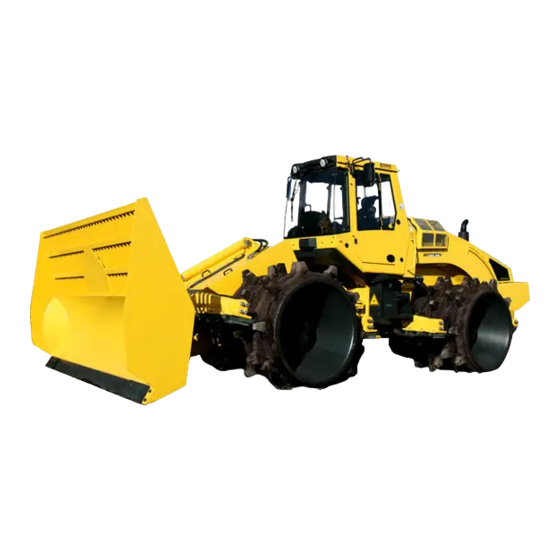
- Page 35 Refuse compactor - earth compactor BC 462 RB – Refuse compactor with dozer blade (21 t). BC 472 RB – Refuse compactor with dozer blade (24 t). BC 472 RS – Refuse compactor with bucket (25 t). BC 462 EB – Fast running earth compactor (21 t). 008 917 13 BOMAG...
- Page 36 Refuse compactor - earth compactor Oscillating articulated joint: +/- 40° steering angle +/- 15° Oscillation of frame Fully closed frame Highly effective wheel and scraper system. Special wheel concept for optimal compaction The perfect combination of application optimized technology Highest possible compaction of soil and refuse as well as traction for all wheel versions, because the wheels are kept clean by the adjustable scraper system.
- Page 37 Refuse compactor - earth compactor Refuse compactor wheel with teeth - Refuse compactor wheel with teeth and segments. basic version for low refuse quantities. for highest compaction No coiling up of wires by the wheels due to Earth compactor with tamper feet and segments wire deflector on the refuse compactor Easy transportation due to the narrow profile 008 917 13...
- Page 38 Refuse compactor - earth compactor Refuse compactor bucket version with full truck loading height BOMAG 008 917 13...
- Page 39 3 Technical data 008 917 13 BOMAG...
- Page 40 Technical data Technical data Fig. 13 Dimensions in mm A 3500 2998 2660 2885 1660 3390 1990 8290 BC 462 RB 3500 3600 2660 3335 1660 3390 1990 8290 BC 472 RB BC 462 RB BC 472 RB Weights Operating weight (CECE) 21300 24000 Front axle load (CECE)
- Page 41 This as a preview PDF file from best-manuals.com Download full PDF manual at best-manuals.com...
Need help?
Do you have a question about the BOMAG BC 462 RB and is the answer not in the manual?
Questions and answers