Table of Contents
Advertisement
Instruction manual
Instruction manual
Operating & Maintenance
Operating & Maintenance
Kubota D1703 / D1803 / V2203 / V2403
Kubota D1703 / D1803 / V2203 / V2403
CC1100 VI
CC1100 VI
(Stage IIIA (26 kW)
(Stage IIIA (26 kW)
CC1100 VI
CC1100 VI
(Tier 4f) (18.5 kW)
(Tier 4f) (18.5 kW)
CC1100 VI
CC1100 VI
(Tier 4f) (28 kW)
(Tier 4f) (28 kW)
CC1100 VI
CC1100 VI
(Stage V) (18.5 kW)
(Stage V) (18.5 kW)
CC1100 VI
CC1100 VI
(Stage V) (28 kW)
(Stage V) (28 kW)
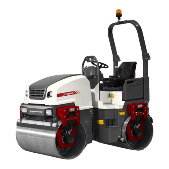
CC1200 VI
CC1200 VI
(Stage IIIA (26 kW)
(Stage IIIA (26 kW)
CC1200 VI
CC1200 VI
(Tier 4f) (18.5 kW)
(Tier 4f) (18.5 kW)
CC1200 VI
CC1200 VI
(Tier 4f) (28 kW)
(Tier 4f) (28 kW)
CC1200 VI
CC1200 VI
(Stage V) (18.5 kW)
(Stage V) (18.5 kW)
CC1200 VI
CC1200 VI
(Stage V) (28 kW)
(Stage V) (28 kW)
CC1300 VI
CC1300 VI
(Stage IIIA (35 kW)
(Stage IIIA (35 kW)
CC1300 VI
CC1300 VI
(Tier 4f) (37 kW)
(Tier 4f) (37 kW)
CC1300 VI
CC1300 VI
(Stage V) (37 kW)
(Stage V) (37 kW)
CC1400 VI
CC1400 VI
(Stage IIIA (35 kW)
(Stage IIIA (35 kW)
CC1400 VI
CC1400 VI
(Tier 4f) (37 kW)
(Tier 4f) (37 kW)
CC1400 VI
CC1400 VI
(Stage V) (37 kW)
(Stage V) (37 kW)
4812164501.pdf
4812164501.pdf
Vibratory rollers
Vibratory rollers
CC1100 VI - CC1400 VI
CC1100 VI - CC1400 VI
Engine
Engine
Models and PIN
Models and PIN
10000389xxA018679 -
10000389xxA018679 -
10000390xxA021827 - xA023287
10000390xxA021827 - xA023287
10000391xxA021487 -
10000391xxA021487 -
10000444xxA024596 -
10000444xxA024596 -
10000452xxA026395 -
10000452xxA026395 -
10000395xxA018609 -
10000395xxA018609 -
10000396xxA018676 -
10000396xxA018676 -
10000397xxA016877 -
10000397xxA016877 -
10000446xxA023389 -
10000446xxA023389 -
10000454xxA031142 -
10000454xxA031142 -
10000469xxA030704 -
10000469xxA030704 -
10000470xxA031597 -
10000470xxA031597 -
10000471xxA030199 -
10000471xxA030199 -
10000475xxA026843 -
10000475xxA026843 -
10000476xxA030197 -
10000476xxA030197 -
10000477xxA026844 -
10000477xxA026844 -
Translation of original instruction
Translation of original instruction
Reservation for changes
Reservation for changes
Printed in Sweden
Printed in Sweden
Advertisement
Table of Contents

Subscribe to Our Youtube Channel
Related Manuals for Fayat Dynapac CC1100 VI


Summary of Contents for Fayat Dynapac CC1100 VI
- Page 1 Instruction manual Instruction manual Operating & Maintenance Operating & Maintenance 4812164501.pdf 4812164501.pdf Vibratory rollers Vibratory rollers CC1100 VI - CC1400 VI CC1100 VI - CC1400 VI Engine Engine Kubota D1703 / D1803 / V2203 / V2403 Kubota D1703 / D1803 / V2203 / V2403 Models and PIN Models and PIN CC1100 VI...
-
Page 3: Table Of Contents
Table of Contents Introduction ..........................1 The machine ....................1 Intended use ....................1 Training ....................... 1 Signal symbols and meaning ..............1 Safety information ..................1 General ....................... 2 CE marking and Declaration of conformity..........3 Safety - General instructions....................5 Safety - when operating ...................... - Page 4 Dimensions, top view (CC1300VI - CC1400VI) ........17 Dimensions, side view (CC1100VI - CC1200VI)........18 Dimensions, side view (CC1300VI - CC1400VI)........19 Weights and volumes................20 Working capacity..................20 General ..................... 23 -emission.................... 23 Tightening torque ..................24 ROPS - bolts ..................... 25 Foldable ROPS - bolts ................
- Page 5 Info decals....................40 Instruments/Controls ....................41 Locations - Control panel and controls............41 Function description .................. 42 Function description - Alarm ..............43 Machine alarm................... 44 Functional description - Membrane panel ..........45 Function description, buttons on Forward/Reverse lever......47 Speed adjustment and vibration frequency (CC1100/C VI - CC1400/C VI with single amplitude) ................
- Page 6 Electrical system...................... 62 Fuses on machine (CC1100 VI / CC1200 VI) ........... 62 Fuses on machine (CC1300 VI / CC1400 VI) ........... 63 Fuses at battery master disconnect switch ..........64 Relays on machine..................65 Operation ..........................67 Before starting ......................67 Master switch - Switching on..............
- Page 7 Emergency braking ................... 79 Switching off....................80 D1703 / V2203-M-E3B..............80 D1803 / V2403-CR-E4B / V2403-CR-E5B........80 Parking ........................81 Chocking the drums .................. 81 Battery disconnector ................. 81 Long-term parking........................83 Engine ....................... 83 Battery....................... 83 Air cleaner, exhaust pipe................83 Fuel tank ....................
- Page 8 Securing CC1100/C VI - CC1200/C VI for loading (Side along the trailer) ......................94 Securing CC1100/C VI - CC1200/C VI for loading (Side across the trailer) ......................98 Securing CC1300/C VI - CC1400/C VI for loading........100 Foldable ROPS ..................102 Operating instructions - Summary ..................
- Page 9 Hydraulic reservoir, Level check - Filling..........124 Air circulation - Check ................124 Fuel tank - Filling..................125 Water tank - Filling .................. 125 Sprinkler system/Drum Checking - Cleaning................126 Sprinkler - Drain / Anti-freeze..............126 Sprinkler system/Drum Cleaning of sprinkler nozzle ..............127 Scrapers, fixed Checking - Setting...................
- Page 10 Check - Coolant system ................144 Check - Air intake hoses ................. 145 Function of the cooling water system (CC1100/C VI - CC1200/C VI)..146 Check - Coolant system ................146 Filling coolant ..................146 Function of the cooling water system (CC1300/C VI - 1400/C VI) ..147 Check - Coolant system ................
- Page 11 Coolers Checking - Cleaning................162 Maintenance - 1000h ......................163 Battery - Check condition ..................163 Engine oil and oil filter - Change ............. 164 Drum - oil level Inspection - filling ..................166 Rubber elements and bolted joints Check ...................... 167 Hydraulic reservoir cap - Check ..............
- Page 12 Checking of injector tip................177 Replacing the oil separator ..............177 Maintenance - 2000h ......................179 Battery - Check condition ..................179 Engine oil and oil filter - Change ............. 180 Rubber elements and bolted joints Check ...................... 182 Hydraulic reservoir cap - Check .............. 182 Steering cylinder and steering joint - Lubrication ........
- Page 13 Steering joint - Check................195 Maintenance, 3000h ......................197 Battery - Check condition ..................197 Engine oil and oil filter - Change ............. 198 Drum - oil level Inspection - filling ..................200 Rubber elements and bolted joints Check ...................... 201 Hydraulic reservoir cap - Check ..............
- Page 14 Cleaning of DPF (D1803 and V2403-CR (Tier 4f / Stage V) only) ..214 Checking the injection pump (D1703 and V2203-M (Stage IIIA) only)..214 Checking the EGR system (D1803 and V2403-CR (Tier 4f / Stage V) only) ......................214 Steering joint - Check................
-
Page 15: Introduction
Introduction Introduction The machine Dynapac CC1100 VI - CC1400 VI are four vibratory tandem rollers in the 2 to 4-tonnes class with 1100 - 1400 mm wide drums. They feature power drive, brakes, and vibration on both drums. Intended use... -
Page 16: General
Introduction We recommend that the operator reads the We recommend that the operator reads the safety instructions in this manual carefully. safety instructions in this manual carefully. Always follow the safety instructions. Ensure Always follow the safety instructions. Ensure that this manual is always easily accessible. that this manual is always easily accessible. -
Page 17: Ce Marking And Declaration Of Conformity
Introduction Do not spray with high-pressure cleaner directly onto gaskets and bearing spacings in steering hitch and drum, and electronics. Inspect the machine every day, before starting. Inspect the entire machine so that any leakages or other faults are detected. Check the ground under the machine. - Page 18 Introduction 4812164501.pdf 2021-05-06...
-
Page 19: Safety - General Instructions
Safety - General instructions Safety - General instructions (Also read the safety manual) • • The operator must be familiar with the contents of the OPERATION section The operator must be familiar with the contents of the OPERATION section before starting the roller. before starting the roller. - Page 20 Safety - General instructions • • Hearing protection is recommended if the noise level exceeds 80 dB(A). The Hearing protection is recommended if the noise level exceeds 80 dB(A). The noise level can vary depending on the equipment on the machine and the noise level can vary depending on the equipment on the machine and the surface the machine is being used on.
-
Page 21: Safety - When Operating
Safety - when operating Safety - when operating Prevent persons from entering or remaining in Prevent persons from entering or remaining in the risk zone, i.e. a distance of at least 7 m (23 the risk zone, i.e. a distance of at least 7 m (23 ft) in all directions from operating machines. -
Page 22: Driving Near Edges
Safety - when operating Driving near edges Never operate with the drum outside the edge, the Never operate with the drum outside the edge, the substrate might not have full bearing strength or substrate might not have full bearing strength or the edge is close to a slope. -
Page 23: Safety (Optional)
Safety (Optional) Safety (Optional) Edge cutter/compactor The operator must make sure that nobody is in the The operator must make sure that nobody is in the area of operation while the machine is in use. area of operation while the machine is in use. The edge cutter consists of rotating components The edge cutter consists of rotating components and there is a risk of being crushed. -
Page 24: Chip Spreader
Safety (Optional) Chip spreader The machine must not be lifted or transported on The machine must not be lifted or transported on another vehicle with chips in the chip spreader. another vehicle with chips in the chip spreader. The weight for the chip spreader is specified on The weight for the chip spreader is specified on the unit rating plate. -
Page 25: Special Instructions
Special instructions Special instructions Standard lubricants and other recommended oils and fluids Before leaving the factory, the systems and components are filled with the oils and fluids specified in the lubricant specification. These are suitable for ambient temperatures in the range -15°C to +40°C (5°F - 105°F). -
Page 26: Fire Fighting
Special instructions Do not spray with high-pressure cleaner directly onto gaskets and bearing spacings in steering hitch and drum, and electronics. Never aim the water jet directly at the fuel tank Never aim the water jet directly at the fuel tank cap, or into exhaust pipe. -
Page 27: Battery Handling
Special instructions Battery handling When removing batteries, always disconnect the When removing batteries, always disconnect the negative cable first. negative cable first. When fitting batteries, always connect the When fitting batteries, always connect the positive cable first. positive cable first. Dispose of old batteries in an environmentally Dispose of old batteries in an environmentally friendly way. - Page 28 Special instructions 4812164501.pdf 2021-05-06...
-
Page 29: Technical Specifications
Technical specifications Technical specifications Vibrations - Operator station (ISO 2631) The vibration levels are measured in accordance with the operational cycle described in The vibration levels are measured in accordance with the operational cycle described in EU directive 2000/14/EC on machines equipped for the EU market, with vibration switched EU directive 2000/14/EC on machines equipped for the EU market, with vibration switched on, on soft polymer material and with the operator’s seat in the transport position. -
Page 30: Dimensions, Top View (Cc1100Vi - Cc1200Vi)
Technical specifications Dimensions, top view (CC1100VI - CC1200VI) Dimensions Dimensions Machine width Machine width CC1100 VI CC1100 VI 1210 1210 CC1200 VI CC1200 VI 1340 1340 B (without ROPS) B (without ROPS) Machine width Machine width CC1100 VI CC1100 VI 1210 1210 CC1200 VI... -
Page 31: Dimensions, Top View (Cc1300Vi - Cc1400Vi)
Technical specifications Dimensions, top view (CC1300VI - CC1400VI) Dimensions Dimensions Machine width Machine width CC1300 VI CC1300 VI 1425 1425 CC1400 VI CC1400 VI 1505 1505 B (without ROPS) B (without ROPS) Machine width Machine width CC1300 VI CC1300 VI 1510 1510 59.4... -
Page 32: Dimensions, Side View (Cc1100Vi - Cc1200Vi)
Technical specifications Dimensions, side view (CC1100VI - CC1200VI) Dimensions Dimensions Wheel base Wheel base 1700 1700 Diameter, drum Diameter, drum Height, with ROPS Height, with ROPS 2542 2542 Height, without ROPS Height, without ROPS 1744 1744 68.5 68.5 Length Length 2400 2400 Length, with chip spreader... -
Page 33: Dimensions, Side View (Cc1300Vi - Cc1400Vi)
Technical specifications Dimensions, side view (CC1300VI - CC1400VI) Dimensions Dimensions Wheel base Wheel base 1970 1970 Diameter, drum Diameter, drum CC1300 VI CC1300 VI 34.6 34.6 CC1400 VI CC1400 VI 34.7 34.7 Height, with ROPS Height, with ROPS 2740 2740 Height, without ROPS Height, without ROPS 2025... -
Page 34: Weights And Volumes
Technical specifications Weights and volumes Fluid volumes Fluid volumes CC1100 VI - CC1200 VI CC1100 VI - CC1200 VI Fuel tank Fuel tank 46 liters 46 liters 48.6 qts 48.6 qts Water tank Water tank 205 liters 205 liters 216.6 qts 216.6 qts CC1300 VI - CC1400 VI CC1300 VI - CC1400 VI... - Page 35 Technical specifications Compaction data (CC1100 VI - CC1200 VI) Compaction data (CC1100 VI - CC1200 VI) Static linear load (front/rear) Static linear load (front/rear) CC1100 VI CC1100 VI 10.7/11.8 kg/cm 10.7/11.8 kg/cm 59.9/66.1 pli 59.9/66.1 pli CC1200 VI CC1200 VI 10.3/11.4 kg/cm 10.3/11.4 kg/cm 57.7/63.8 pli...
- Page 36 Technical specifications Compaction data (CC1300 VI - CC1400 VI) Compaction data (CC1300 VI - CC1400 VI) Static linear load (front/rear) Static linear load (front/rear) CC1300 VI CC1300 VI 14.3/15.7 kg/cm 14.3/15.7 kg/cm 80/88 pli 80/88 pli CC1400 VI CC1400 VI 15.1/16.1 kg/cm 15.1/16.1 kg/cm 85/90 pli...
-
Page 37: General
Technical specifications General Engine Engine Manufacturer/Model Manufacturer/Model Effect (SAE J1995) Effect (SAE J1995) Kubota D1703-M-IDI E3B (Stage IIIA) Kubota D1703-M-IDI E3B (Stage IIIA) 26.1 kW (35 hp) 26.1 kW (35 hp) 2800 rpm 2800 rpm Kubota D1703-M-DI-E4B (Tier 4f, Stage Kubota D1703-M-DI-E4B (Tier 4f, Stage 18.5 kW (25 hp) 18.5 kW (25 hp) 2200 rpm... -
Page 38: Tightening Torque
Technical specifications Tightening torque Tightening torque in Nm for oiled or dry bolts tightened with a torque wrench. Metric coarse screw thread, bright galvanized (fzb): STRENGTH CLASS: 8.8, Oiled 8.8, Oiled 8.8, Dry 8.8, Dry 10.9, Oiled 10.9, Oiled 10.9, Dry 10.9, Dry 12.9, Oiled 12.9, Oiled... -
Page 39: Rops - Bolts
Technical specifications ROPS-bolts which are to be torque tightened ROPS-bolts which are to be torque tightened must be dry. must be dry. ROPS - bolts Bolt dimensions : Bolt dimensions : M16 (PN 4700902889) M16 (PN 4700902889) Strength class : Strength class : - CC1100/C VI - CC1200/C - CC1100/C VI - CC1200/C... -
Page 40: Hydraulic System
Technical specifications Hydraulic system Opening pressure (Absolute Opening pressure (Absolute pressure) pressure) CC1100 VI - CC1200 VI CC1100 VI - CC1200 VI CC1300 VI - CC1400 VI CC1300 VI - CC1400 VI Drive system Drive system 35.0 35.0 35.0 35.0 Supply system Supply system Vibration system... -
Page 41: Machine Description
Machine description Machine description Diesel engine The machine is equipped with a water-cooled, in-line three or four cylinder, four-stroke diesel engine. Electrical system The machine has the following control units (ECU, Electronic Control Unit) and electronic units. • Main ECU (for the machine) •... -
Page 42: Identification
Machine description ROPS structure must be replaced immediately. Never perform any modifications on the ROPS structure without first having discussed the modification with Dynapac's production unit. Dynapac determines whether the modification could result in the approval according to the ROPS standards becoming invalid. -
Page 43: Product Identification Number On The Frame
Machine description Product identification number on the frame The machine PIN (product identification number) (1) is punched on the right side of the front frame. Fig. PIN Front frame 1. Serial number Explanation of 17PIN serial number A= Manufacturer 00123 00123 123456 123456... -
Page 44: Machine Plate
Machine description Machine plate The machine type plate (1) is affixed on the rear left edge of the frame. The plate includes: • name and address of the manufacturer (2) • type of machine (3) • PIN-product identification number (serial number) (4) •... - Page 45 Machine description Please specify the engine serial number when ordering spares. Refer also to the engine manual. Fig. Engine - D1703-M-IDI-E3 (Stage IIIA) 1. Type plate 2. Engine series plate Fig. Engine - D1703-M-DI-E4B (Tier 4f, Stage Fig. Engine - D1803-CR (Tier 4f, Stage V) 1.
- Page 46 Machine description Fig. Engine - V2203-M (Stage IIIA) Fig. Engine - V2403-CR (Tier 4f / Stage V) 1. Type plate 1. Type plate 2. Engine series plate 2. Engine series plate 4812164501.pdf 2021-05-06...
-
Page 47: Location - Decals (Cc1100 Vi / Cc1200 Vi)
Machine description Location - decals (CC1100 VI / CC1200 VI) 6, 17 Fig. Location, decals and signs Warning, Crush zone Warning, Crush zone 4700903422 4700903422 Sound power level Sound power level 4700791292 4700791292 Warning, Rotating engine Warning, Rotating engine 4700903423 4700903423 Hydraulic fluid level Hydraulic fluid level... - Page 48 Machine description 4812164501.pdf 2021-05-06...
-
Page 49: Location - Decals (Cc1300 Vi / Cc1400 Vi)
Machine description Location - decals (CC1300 VI / CC1400 VI) 6, 17 Fig. Location, decals and signs Warning, Crush zone Warning, Crush zone 4700903422 4700903422 Sound power level Sound power level 4700791292 4700791292 Warning, Rotating engine Warning, Rotating engine 4700903423 4700903423 Hydraulic fluid level Hydraulic fluid level... -
Page 50: Location - Decals, California
Machine description Location - decals, CALIFORNIA Proposition 65 Warning, CALIFORNIA Warning, CALIFORNIA 4812129673 4812129673 Proposition 65 Proposition 65 Fig. Location Safety decals Always make sure that all safety decals are completely legible, and remove dirt or order new decals if they have become illegible. - Page 51 Machine description 4700903459 Warning - Instruction manual The operator must read the safety, operation and maintenance instructions before operating the machine. 4700904083 Warning - Edge cutter (optional) Warning of rotating parts. Maintain a safe distance from the crush zone. 4700903422 Warning - Crush zone, chip spreader (optional) Risk of personal injury or being crushed.
- Page 52 Machine description 4811000080 Warning - Chip spreader (optional) The spreader has rotating components. Never insert your hands or any objects when the spreader is in operation. Always stop the roller motor before carrying out adjustments or maintenance on the spreader. 4812164501.pdf 2021-05-06...
- Page 53 Machine description 4812129673 Warning CALIFORNIA - Proposition 65 2021-05-06 4812164501.pdf...
-
Page 54: Info Decals
Machine description Info decals Noise power level Noise power level Diesel fuel Diesel fuel Lifting point Lifting point Manual compartment Manual compartment Battery disconnector Battery disconnector Fixing point Fixing point Bio hydraulic fluid, PANOLIN Hydraulic fluid level Bio hydraulic fluid, PANOLIN Hydraulic fluid level Water Water Flow divider (optional) -
Page 55: Instruments/Controls
Machine description Instruments/Controls Locations - Control panel and controls Fig. Operator's Fig. Operator position station Ignition key Ignition key Fuse holder Fuse holder Direction selector / Direction selector / indicator indicator Engine speed control Engine speed control Instrument cover Instrument cover Emergency stop Emergency stop (D1703 / V2203-M) -
Page 56: Function Description
Machine description Function description Designation Designation Symbol Symbol Function Function Throttle control Throttle control In forward position, the engine idles. In forward position, the engine idles. In backward position, the engine runs at full speed. In backward position, the engine runs at full speed. Seat switch Seat switch Remain seated at all times when operating the roller. -
Page 57: Function Description - Alarm
Machine description Function description - Alarm No Symbol Designation and Function No Symbol Designation and Function Warning lamp (Red) Warning lamp (Red) Serious fault: Switch off engine Serious fault: Switch off engine immediately! immediately! Launched together with a message on Launched together with a message on the display. -
Page 58: Machine Alarm
Machine description Machine alarm Symbol Symbol Designation Designation Function Function Warning symbol, hydraulic fluid filter Warning symbol, hydraulic fluid filter If the symbol is shown when the diesel engine is running at If the symbol is shown when the diesel engine is running at full speed, the hydraulic fluid filter must be changed. -
Page 59: Functional Description - Membrane Panel
Machine description Functional description - Membrane panel Working mode Vibration, high/low amplitude (CC1300/C VI - CC1400/C VI only) Rotating beacon Working lights Sprinkler timer Sprinkler, manual / automatic Engine speed selector Horn (D1803 / V2403-CR) Designation Function Designation Function color color Working Working... - Page 60 Machine description Designation Function Designation Function color color Working Working Enables working lights for ROPS and / or Frame Enables working lights for ROPS and / or Frame lights, switch lights, switch LED OFF = OFF LED OFF = OFF LED LEFT = Working lights, Frame LED LEFT = Working lights, Frame LED RIGHT = Working lights, Frame and...
-
Page 61: Function Description, Buttons On Forward/Reverse Lever
Machine description Function description, buttons on Forward/Reverse lever Left lever (LH) Right lever (RH) Mode / Button Mode / Button Button 1 Button 1 Button 2 Button 2 Button 3 Button 3 Transport mode Transport mode None None None None Edge cutter, up Edge cutter, up Working mode... -
Page 62: Speed Adjustment And Vibration Frequency (Cc1100/C Vi - Cc1400/Cvi With Single Amplitude)
Machine description Speed adjustment and vibration frequency (CC1100/C VI - CC1400/C VI with single amplitude) Mechanical speed control If the speed control is in the center position / ECO (2), both the engine speed and vibration frequency are low. If the speed control is in the lowermost position / ECO (3), both the engine speed and vibration frequency are high. -
Page 63: Navigation Submenus
Machine description Navigation submenus Stage IIIA Stage IIIA Navigation sequence Navigation sequence Stage V / Tier 4f Stage V / Tier 4f Submenu Submenu Transport mode / Machine hours Transport mode / Machine hours 1st press 1st press Transport mode / Machine hours Transport mode / Machine hours Error code list Error code list... -
Page 64: Transport Mode
Machine description Transport mode The transport mode screen provides information about travel direction (3), machine hours (4) and fuel level (2). 2. Fuel level: - The fuel level is indicated as a percentage (%) on the bar to the right of the display. When only the lowest step on the bar is filled, there is 10% of the fuel remaining in the tank and the warning lamp for the fuel level (6) lights. -
Page 65: Submenu - Regeneration (D1803 (Tier 4F, Stage V) / V2403-Cr (Tier 4F, Stage V))
Machine description Submenu - Regeneration (D1803 (Tier 4f, Stage V) / V2403-CR (Tier 4f, Stage V)) Regeneration is activated using the button (1) on the right-hand side of the display. Parked regeneration requires the following conditions to be met: - FNR/selector lever in neutral position Fig. - Page 66 Machine description Level 3 If the symbol (1) on the display Flashes, Red warning lamp is lit and error code SPN 3701 / FMI 15 is launched in the error code list, a Parked regeneration is required. Satisfy the conditions for Parked regeneration and perform this immediately.
-
Page 67: Submenu - Error Code List
Machine description Submenu - Error code list 1. The alarm symbols are shown on the left-hand side of the display. At the top is the red (5) warning symbol and at the bottom the yellow (6). Alarms are categorized in different degrees of severity: White alarm: The lowest degree of severity. -
Page 68: User Settings
Machine description User settings The user can change the light settings (day mode (9) / night mode (10)), choose between the Metric or Imperial unit system (14) and also read version of installed software for display (11) and ECU (12). Fig. -
Page 69: Service Menu
Machine description "SERVICE MENU" The service menu is also accessible via the main menu for adjustments. "ADJUSTMENTS" CALIBRATION - service personnel only, requires a PIN code. The value of the number increases or decreases using button 1 or 3 respectively. Button 2 confirms the value and the indication moves to the next number. -
Page 70: Working Mode, Vibration
Machine description Working mode, Vibration The different working modes are selected with the help of the working mode button on the panel. 1. Optional asphalt temperature meter (see the chapter asphalt temperature meter) Symbols are shown in the menu Working mode, vibration for forward and rear drums. -
Page 71: Working Mode, Vibration With Dual Amplitudes (Optional) (Cc1300 Vi - 1400 Vi With V2403-Cr (Tier 4F / Stage V) Engine)
Machine description Working mode, Vibration with dual amplitudes (Optional) (CC1300 VI - 1400 VI with V2403-CR (Tier 4f / Stage V) engine) - The speed changes automatically from medium to high on activation of vibration with low amplitude, provided that high has not already been selected. - The speed decreases automatically from high to medium, on activation of vibration with High amplitude if medium speed has not already been selected. -
Page 72: Working Mode - Edge Cutter
Machine description Working mode - Edge cutter The different working modes are selected with the help of the working mode button on the panel. In Working mode, Edge cutter a symbol is shown for the drum (front drum) and the symbol for the edge cutter (6). -
Page 73: Working Mode - Chip Spreader
Machine description Working mode - Chip spreader The different working modes are selected with the help of the button on the panel. In Working mode, Chip spreader a symbol is shown for the drum (front drum) and the symbol for the chip spreader (3). -
Page 74: Asphalt Temperature Meter (Optional)
Machine description Asphalt temperature meter (Optional) With the side menu (6) active, the asphalt temperature meter is accessed by pressing the button (7). The asphalt temperature is displayed in the upper right corner (8) and the temperature display flashes if the temperature is outside the preset limits. -
Page 75: Operator Help When Starting
Machine description Operator help when starting To start the diesel engine requires the following conditions to be met: - Activated parking brake - Control lever in neutral - Engine speed selector in low position (Low = idling). Applies only to CR engines (electronically controlled engines) and there is no operator assistance here. -
Page 76: Electrical System
Machine description Electrical system Fuses on machine (CC1100 VI / CC1200 VI) The figure shows the position of the fuses. The table below gives fuse amperage and function. All fuses are flat pin fuses. Fig. Fuse box Fuse box Fuse box 1. -
Page 77: Fuses On Machine (Cc1300 Vi / Cc1400 Vi)
Machine description Electrical system Fuses on machine (CC1300 VI / CC1400 VI) The figure shows the position of the fuses. The table below gives fuse amperage and function. All fuses are flat pin fuses. Fig. Fuse box Fuse box Fuse box 1. -
Page 78: Fuses At Battery Master Disconnect Switch
Machine description Fuses at battery master disconnect switch The figure shows the different positions of the fuses in the engine compartment. The table below gives fuse amperage and function. All fuses are flat pin fuses. D1703 / V2203-M-E3B (Stage IIIA) Main fuse Main fuse Glowing, Start relay, Fuel... -
Page 79: Relays On Machine
Machine description The control unit (ECU) (1) is located under the floor plate (2) on the platform. This control unit manages, among others, automatic vibration control, automatic watering control and interlock. Relays on machine Fig. Operator's station 1. Control unit (ECU) 2. - Page 80 Machine description Engine compartment (D1803 / V2403-CRE4B (Tier 4f) / V2403-CRE5B (Stage V)) Start relay Start relay Engine ECU relay Engine ECU relay Glowing relay Glowing relay Fig. Relays Engine compartment (D1803 / V2403-CR-E4B / V2403-CRE5B) Steering column K6.1 K6.1 Working lights frame Working lights frame K6.2...
-
Page 81: Operation
Operation Operation Before starting Master switch - Switching on Perform daily maintenance. See the maintenance instructions. The battery disconnector is on the left side in the engine compartment. Turn the key (1) to switched on position. The roller is now supplied with power. The engine hood must be unlocked during The engine hood must be unlocked during operation, unless the battery disconnector is freely... -
Page 82: Driver Seat - Adjustment
Operation Driver seat - Adjustment Adjust the operator’s seat so that the position is comfortable and so that the controls are within easy reach. The tables below show the adjustments that can be made on the different seats. The image below to the left shows a fully equipped luxury comfort seat while the image below to the right shows a normally equipped comfort seat. -
Page 83: Parking Brake - Check
Operation Fig. Driver seat (MSG65) 5. Lumbar support adjustment 6. Backrest extension 7. Armrest, adjustable 8. Seat heating Lumbar Lumbar Backrest Backrest Armrest, Armrest, Seat heating (8) Seat heating (8) support support extension (6) extension (6) adjustable (7) adjustable (7) adjustment (5) adjustment (5) Standard seat... -
Page 84: Reserve Brake - Control
Operation The engine can only be started with the parking The engine can only be started with the parking brake (6) activated. brake (6) activated. Reserve brake - Control Drive slowly fowards/backwards and press down the parking brake button (6) to activate it. The roller must now stop immediately. -
Page 85: Interlock
Operation Interlock The roller is equipped with Interlock. The diesel engine with switch off after 4 seconds if the operator gets off the seat when going forwards/backwards. If the control is in neutral when the operator stands up a buzzer will go on until the parking brake button is activated. -
Page 86: Adjusting The Off-Set
Operation Adjusting the Off-set Lift up the front drum just above ground level. Place a jack on the rear frame, to support the articulated joint, and loosen the nuts on the articulated joint (1). Position yourself on the right or left-hand side of the articulated joint. -
Page 87: Starting
Operation Starting Starting the engine The operator must remain seated when starting. The operator must remain seated when starting. Make sure that the emergency stop (3) is pulled out and the parking brake (31) is activated. Set the forward/reverse lever (6) in neutral. The engine can only be started when the lever is in neutral. - Page 88 Operation Check while warming up the engine that no warning lamps are lit. The parking brake lamp (25) will remain on for as long as the parking brake switch is activated. When starting and driving a machine that is cold, When starting and driving a machine that is cold, remember that the hydraulic fluid is also cold and remember that the hydraulic fluid is also cold and...
-
Page 89: Driving
Operation Driving Operating the roller Under no circumstances is the machine to be Under no circumstances is the machine to be operated from the ground. The operator must be operated from the ground. The operator must be seated inside the machine during all operation. seated inside the machine during all operation. -
Page 90: Interlock/Emergency Stop/Parking Brake - Check
Operation Interlock/Emergency stop/Parking brake - Check The interlock, emergency stop and parking brake must The interlock, emergency stop and parking brake must be checked daily before operating. A function check of be checked daily before operating. A function check of the interlock and emergency stop requires a restart. -
Page 91: Edge Cutting (Optional)
Operation Edge cutting (Optional) The machine must be running to activate the edge cutter/compactor. With the machine in Working mode/Edge cutter (20) (middle LEDs lit) the edge cutter/compactor is controlled up and down with the help of button (3) and button (2) on the control lever. -
Page 92: Vibration
Operation Vibration Manual/Automatic vibration In Working mode/Vibration (20) (LED LEFT lit) you can select, manually, which drum is to vibrate with the button on the forward/reverse lever. For Standard machine: Button (1) activates vibration on on both the drums. For machines equipped with the accessory - individual vibrations shutoff: Fig. -
Page 93: Braking
Operation Braking Normal braking Turn off the vibration using the buttons (1) and (2) on the control lever. Move the forward/reverse lever (6) to the neutral position to stop the roller. When starting and driving a machine that is cold, When starting and driving a machine that is cold, remember that the hydraulic fluid is also cold and remember that the hydraulic fluid is also cold and... -
Page 94: Switching Off
Operation Switching off Activate the parking brake (31). D1703 / V2203-M-E3B Turn the engine speed control (2) back to idling. D1803 / V2403-CR-E4B / V2403-CR-E5B Press the LED button (32) so it is set to LOW mode (left LED lit). Fig. -
Page 95: Parking
Operation Parking Chocking the drums Never disembark from the roller when the diesel Never disembark from the roller when the diesel engine is running, without first activating the engine is running, without first activating the parking brake. parking brake. Make sure that the roller is parked in a safe place Make sure that the roller is parked in a safe place with respect to other road users. - Page 96 Operation 4812164501.pdf 2021-05-06...
-
Page 97: Long-Term Parking
Long-term parking Long-term parking The following instructions should be followed The following instructions should be followed when long term parking (more than one month). when long term parking (more than one month). These measures apply when parking for a period of up to 6 months. -
Page 98: Steering Cylinder, Hinges, Etc
Long-term parking Steering cylinder, hinges, etc. Lubricate the steering joint bearings and the steering cylinder's two bearings with grease. Grease the piston rod of the steering cylinder with inhibitor grease. Grease the hinges on the engine compartment hood and also grease both ends of the forward/reverse control (bright parts). -
Page 99: Miscellaneous
Miscellaneous Miscellaneous Lifting Locking the articulation Articulation must be locked to prevent inadvertent Articulation must be locked to prevent inadvertent turning before lifting the roller. turning before lifting the roller. Turn the steering wheel to the straight ahead position. Enable the parking brake. Pull out the locking pin (2) fitted with a wire, and pull up/out the locking dowel (3). -
Page 100: Lifting The Roller
Miscellaneous Weight: see the machine plate on the roller Lifting the roller The maximum weight of the machine (5) can be The maximum weight of the machine (5) can be read on the machine plate (1). read on the machine plate (1). Lifting equipment such as chains, steel wires, Lifting equipment such as chains, steel wires, straps and lifting hooks must be dimensioned in... -
Page 101: Lifting The Roller With A Single -Point Lift (Optional) (Cc1100/C Vi - Cc1200/C Vi Only)
Miscellaneous Lifting the roller with a single -point lift (Optional) (CC1100/C VI - CC1200/C VI only) The maximum weight of the machine (5) can be The maximum weight of the machine (5) can be read on the machine plate (1). read on the machine plate (1). -
Page 102: Towing/Recovering
Miscellaneous Towing/Recovering The roller can be moved up to 300 meters (330 yards) using the instructions below. Release the brakes Activate the parking brake, and stop the engine. Activate the parking brake, and stop the engine. Block the drum with a chock to prevent movement; Block the drum with a chock to prevent movement;... -
Page 103: Towing The Roller
Miscellaneous Towing the roller The roller must be counter-braked during The roller must be counter-braked during towing/recovery. Always use a towbar. There is no towing/recovery. Always use a towbar. There is no braking capacity on the roller now. braking capacity on the roller now. The roller must be towed slowly, max. -
Page 104: Short Distance Towing With Switched Off Engine
Miscellaneous Short distance towing with switched off engine Chock the drums to prevent the roller from Chock the drums to prevent the roller from moving. moving. Open the hood and make sure that the propulsion pump is accessible. There is a bypass screw (1) located on the pump that must be unscrewed counterclockwise (max two turns), to put the drive system (ports A and B) in bypass mode. -
Page 105: Transport
Miscellaneous Transport Tie-down and secure the machine according to the Cargo Securing Certificate for the specific machine if this is avaliable and applicable. If not, tie down and secure the machine according to the cargo securing rules that are valid for the country where the transport takes place. -
Page 106: Securing Cc1100/C Vi - Cc1200/C Vi For Loading
Miscellaneous Securing CC1100/C VI - CC1200/C VI for loading Securing of a double vibratory roller of model CC1100/C VI - CC1200/C VI from Dynapac loaded on a trailer for transport on road and in the Baltic / North sea (sea area A/B). Direct of travel 1 - 2 = double lashings, i.e. - Page 107 Miscellaneous The drum is placed on a rubber liner, so that the static friction between the surfaces is at least The drum is placed on a rubber liner, so that the static friction between the surfaces is at least 0.6. 0.6.
-
Page 108: Securing Cc1100/C Vi - Cc1200/C Vi For Loading
Miscellaneous Securing CC1100/C VI - CC1200/C VI for loading (Side along the trailer) Securing of two CC1100/C VI - CC1200/C VI vibratory rollers from Dynapac loaded side by side along a trailer for transport on road and in Baltic sea (Sea area Direct of travel 1 - 2 = double lashings, i.e. - Page 109 Miscellaneous Load carrier Load carrier Ensure that: Ensure that: When loaded, the vibratory roller is centered laterally on the platform (± 5 cm). When loaded, the vibratory roller is centered laterally on the platform (± 5 cm). The parking brake is applied and in good working condition, and the articulated joint lock is The parking brake is applied and in good working condition, and the articulated joint lock is closed.
- Page 110 Miscellaneous Securing CC1100/C VI - CC1200/C VI for loading (Side along the trailer) Securing of two CC1100/C VI - CC1200/C VI vibratory rollers from Dynapac loaded side by side along a trailer for transport on road and in North sea (Sea area Direct of travel 1 - 2 = double lashings, i.e.
- Page 111 Miscellaneous Load carrier Load carrier Ensure that: Ensure that: When loaded, the vibratory roller is centered laterally on the platform (± 5 cm). When loaded, the vibratory roller is centered laterally on the platform (± 5 cm). The parking brake is applied and in good working condition, and the articulated joint lock is The parking brake is applied and in good working condition, and the articulated joint lock is closed.
-
Page 112: Securing Cc1100/C Vi - Cc1200/C Vi For Loading (Side Across The Trailer)
Miscellaneous Securing CC1100/C VI - CC1200/C VI for loading (Side across the trailer) Securing of two CC1100/C VI - CC1200/C VI vibratory rollers from Dynapac loaded side by side across a trailer for transport on road and in Baltic sea /North sea (Sea area A/B). - Page 113 Miscellaneous Load carrier Load carrier Ensure that: Ensure that: When loaded, the vibratory roller is centered laterally on the platform (± 5 cm). When loaded, the vibratory roller is centered laterally on the platform (± 5 cm). The parking brake is applied and in good working condition, and the articulated joint lock is The parking brake is applied and in good working condition, and the articulated joint lock is closed.
-
Page 114: Securing Cc1300/C Vi - Cc1400/C Vi For Loading
Miscellaneous Securing CC1300/C VI - CC1400/C VI for loading Securing of a double vibratory roller of model CC1300/C VI - CC1400/C VI from Dynapac loaded on a trailer for transport on road and in the Baltic / North sea (sea area A/B). Direct of travel 1 - 2 = double lashings, i.e. - Page 115 Miscellaneous The drum is placed on a rubber liner, so that the static friction between the surfaces is at least The drum is placed on a rubber liner, so that the static friction between the surfaces is at least 0.6. 0.6.
-
Page 116: Foldable Rops
Miscellaneous Foldable ROPS The machine is equipped with foldable ROPS Risk of crush injury when raising and lowering Risk of crush injury when raising and lowering ROPS. ROPS. Always make sure the ROPS is locked in raised Always make sure the ROPS is locked in raised position before operation position before operation Fig. -
Page 117: Operating Instructions - Summary
Operating instructions - Summary Operating instructions - Summary Follow the SAFETY INSTRUCTIONS specified in the Safety Manual. Follow the SAFETY INSTRUCTIONS specified in the Safety Manual. Make sure that all instructions in the MAINTENANCE section are followed. Make sure that all instructions in the MAINTENANCE section are followed. Turn the master switch to the ON position. - Page 118 Operating instructions - Summary 4812164501.pdf 2021-05-06...
-
Page 119: Preventive Maintenance
Preventive maintenance Preventive maintenance Complete maintenance is necessary for the machine to function satisfactorily and at the lowest possible cost. The Maintenance section includes the periodic maintenance that must be carried out on the machine. The recommended maintenance intervals assume that the machine is used in a normal environment and working conditions. - Page 120 Preventive maintenance CALIFORNIA Proposition 65 Decal and location of decal shown in section Machine description. 4812164501.pdf 2021-05-06...
-
Page 121: Maintenance - Lubricants And Symbols
Maintenance - Lubricants and symbols Maintenance - Lubricants and symbols Always use high-quality lubricants and the Always use high-quality lubricants and the amounts recommended. Too much grease or amounts recommended. Too much grease or oil can cause overheating, resulting in rapid oil can cause overheating, resulting in rapid wear. - Page 122 Maintenance - Lubricants and symbols ENGINE OIL ENGINE OIL Air temperature -15°C - +50°C Air temperature -15°C - +50°C Dynapac Engine Oil Dynapac Engine Oil P/N 4812161855 (5 liter) P/N 4812161855 (5 liter) (5°F-122°F) (5°F-122°F) P/N 4812161856 (20 liter) P/N 4812161856 (20 liter) P/N 4812161857 (209 liter) P/N 4812161857 (209 liter) HYDRAULIC FLUID...
-
Page 123: Maintenance Symbols
Maintenance - Lubricants and symbols Maintenance symbols Engine, oil level Engine, oil level Air filter Air filter Engine, oil filter Engine, oil filter Battery Battery Hydraulic reservoir, level Hydraulic reservoir, level Sprinkler Sprinkler Hydraulic fluid, filter Hydraulic fluid, filter Sprinkler water Sprinkler water Drum, oil level Drum, oil level... - Page 124 Maintenance - Lubricants and symbols 4812164501.pdf 2021-05-06...
-
Page 125: Maintenance - Maintenance Schedule
Maintenance - Maintenance schedule Maintenance - Maintenance schedule Service and maintenance points Fig. Service and maintenance points Fuel tank Fuel tank Sprinkler system Sprinkler system Steering joint Steering joint Refueling Refueling Scrapers Scrapers Steering cylinder, bearings Steering cylinder, bearings Cooler Cooler 10. -
Page 126: General
Maintenance - Maintenance schedule General Periodic maintenance should be carried out after the number of hours specified. Use the daily, weekly etc. periods where number of hours cannot be used. Remove all dirt before filling, when checking Remove all dirt before filling, when checking oils and fuel and when lubricating using oil or oils and fuel and when lubricating using oil or grease. -
Page 127: After The First 50 Hours Of Operation
Maintenance - Maintenance schedule After the FIRST 50 hours of operation See Contents to find the page number of the sections referred to! Pos. Pos. Action Action Comment Comment in fig in fig Change the engine oil and oil filter Change the engine oil and oil filter Refer to the engine manual Refer to the engine manual... -
Page 128: Every 500 Hours Of Operation
Maintenance - Maintenance schedule Every 500 hours of operation See Contents to find the page number of the sections referred to! Pos. Pos. Action Action Comment Comment in fig in fig Check the condition of the battery Check the condition of the battery Change engine oil and oil filter Change engine oil and oil filter Refer to the engine manual... -
Page 129: Every 1000 Hours Of Operation
Maintenance - Maintenance schedule Every 1000 hours of operation See Contents to find the page number of the sections referred to! Pos. Pos. Action Action Comment Comment in fig in fig Check the condition of the battery Check the condition of the battery Change engine oil and oil filter Change engine oil and oil filter Refer to the engine manual... -
Page 130: Every 2000 Hours Of Operation
Maintenance - Maintenance schedule Every 2000 hours of operation See Contents to find the page numbers of the sections referred to! Pos. Pos. Action Action Comment Comment in fig in fig Check the battery condition Check the battery condition Change the engine oil and oil filter Change the engine oil and oil filter Refer to the engine manual Refer to the engine manual... -
Page 131: Every 3000 Hours Of Operation
Maintenance - Maintenance schedule Every 3000 hours of operation See Contents to find the page numbers of the sections referred to! Pos. Pos. Action Action Comment Comment in fig in fig Check the battery condition Check the battery condition Change the engine oil and oil filter Change the engine oil and oil filter Refer to the engine manual Refer to the engine manual... -
Page 132: Every 12Th Month (Annually)
Maintenance - Maintenance schedule Every 12th month (Annually) Refer to the contents to find the page number of the sections referred to ! Pos. Pos. Action Action Comment Comment in fig in fig Replacing the air filters (main and backup filter) Replacing the air filters (main and backup filter) Check the DPF pipes and connections Check the DPF pipes and connections... -
Page 133: Service - Checklist
Maintenance - Maintenance schedule Service - Checklist 2021-05-06 4812164501.pdf... - Page 134 Maintenance - Maintenance schedule 4812164501.pdf 2021-05-06...
-
Page 135: Maintenance, 10H
Maintenance, 10h Maintenance, 10h Every 10 hours of operation (Daily) Park the roller on a level surface. Park the roller on a level surface. The engine must be switched off and the The engine must be switched off and the parking brake activated when checking or parking brake activated when checking or adjusting the roller, unless otherwise specified. -
Page 136: Check - Coolant System
Maintenance, 10h Check - Coolant system Check that all hoses/hose connectors are intact and tight. Fill with coolant as specified in the lubricants specification. Take great care when opening the radiator cap Take great care when opening the radiator cap while the engine is hot. - Page 137 Maintenance, 10h Open the engine cover lock and lower the engine cover forwards. Check the oil level using the dipstick (1). The level should be between the marks. If the level is near the lower mark, top off with fresh engine oil via the filler cap (2).
-
Page 138: Hydraulic Reservoir, Level Check - Filling
Maintenance, 10h Hydraulic reservoir, Level check - Filling Check that the oil level is visible in the sight glass. Open the engine hood and unscrew the filler cap (2), top up with hydraulic fluid (as per lubricant specification) if the level is too low. Screw on the cap again after filling. -
Page 139: Fuel Tank - Filling
Maintenance, 10h Fuel tank - Filling Refuel the tank every day before starting work. Open the engine hood, unscrew the tank cap (1) fill with diesel up to the lower edge of the filler pipe. Tier 4f and Stage V Kubota engines require the Tier 4f and Stage V Kubota engines require the use of Ultra Low Sulphur Diesel (ULSD) fuel, use of Ultra Low Sulphur Diesel (ULSD) fuel,... -
Page 140: Sprinkler System/Drum Checking - Cleaning
Maintenance, 10h Sprinkler system/Drum Checking - Cleaning Start the sprinkler system and make sure that no nozzles (2) are clogged. If necessary, clean clogged nozzles and the coarse filter located by the water pump; see figures below. Make sure that the watering system Make sure that the watering system is empty/drained of water (sprinkler, is empty/drained of water (sprinkler,... -
Page 141: Sprinkler System/Drum Cleaning Of Sprinkler Nozzle
Maintenance, 10h When cleaning the coarse filter (1), open the cock (2) and loosen the filter housing. Clean the filter and filter housing. Check that the rubber gasket in the filter housing is intact. After inspecting and carrying out any necessary cleaning, start the system and check that it works. -
Page 142: Scrapers, Fixed Checking - Setting
Maintenance, 10h Scrapers, fixed Checking - Setting Make sure that the scrapers are undamaged. Adjust the scrapers so that they are 1-2 mm from the drum. For special asphalt compounds, it may be better if the scraper blades (1) lie lightly against the drums. Asphalt remnants can accumulate on the scraper and affect the contact force. -
Page 143: Brakes - Check
Maintenance, 10h Brakes - Check Check operation of the brakes as follows: Check operation of the brakes as follows: Run the roller very slowly forward. Hold the steering wheel firmly and brace yourself for a sudden stop. Make sure the parking brake is deactivated and press Figure. - Page 144 Maintenance, 10h 4812164501.pdf 2021-05-06...
-
Page 145: Maintenance, First 50H
Maintenance, first 50h Maintenance, first 50h Park the roller on a level surface. Park the roller on a level surface. The engine must be switched off and the The engine must be switched off and the parking brake activated when checking or parking brake activated when checking or adjusting the roller, unless otherwise specified. - Page 146 Maintenance, first 50h Place a receptacle that holds at least 12 liters (8 gal.) under the drain plug (2). Undo the oil filler cap (3), and undo the drain plug (2) in the end of the drain hose (1). Let all the engine oil flow out.
-
Page 147: Replacing The Hydraulic Oil Filter
Maintenance, first 50h Replacing the hydraulic oil filter Open the engine hood. Loosen the red cap (1) and pull up the filter insert (4). Refit the red cap temporarily to prevent dust and dirt getting into the tank. Fig. Engine compartment 1. -
Page 148: Bolted Joints Check
Maintenance, first 50h Bolted joints Check Check that all bolted joints (1) are tightened correctly. Fig. Drum forks Fig. Articulated joint 1. Bolted joints 1. Bolted joints 4812164501.pdf 2021-05-06... -
Page 149: Maintenance - 50H
Maintenance - 50h Maintenance - 50h Every 50 hours of operation (Weekly) Park the roller on a level surface. Park the roller on a level surface. The engine must be switched off and the The engine must be switched off and the parking brake activated when checking or parking brake activated when checking or adjusting the roller, unless otherwise specified. -
Page 150: Steering Cylinder And Steering Joint - Lubrication
Maintenance - 50h Steering cylinder and steering joint - Lubrication The machine must be in neutral (straight) when lubricated. All five grease nipples (1) can now be accessed. Wipe the grease nipples (1). Grease each nipple with five strokes of the hand-operated grease gun. Make sure that grease penetrates into the bearing. -
Page 151: Checking The Fuel Hoses And Hose Clamps
Maintenance - 50h Checking the fuel hoses and hose clamps Stop the engine before checking or replacing the Stop the engine before checking or replacing the fuel pipes. Defective fuel pipes can cause a fire. fuel pipes. Defective fuel pipes can cause a fire. If the fuel pipes are not connected, plug them at If the fuel pipes are not connected, plug them at both ends with a clean cloth or paper to prevent dirt... -
Page 152: Water Separator - Draining (On Machines Equipped With This)
Maintenance - 50h Water separator - Draining (on machines equipped with this) If water or contaminates accumulate in the water separator, an indication will be shown on the display. If this should happen during operation, drain from the draining plug. (1). Fig. -
Page 153: Maintenance Measures - 250 H
Maintenance measures - 250 h Maintenance measures - 250 h Every 250/750/1250/1750..hours of operation (every 3 months) Park the roller on a level surface. Park the roller on a level surface. The engine must be switched off and the The engine must be switched off and the parking brake activated when checking or parking brake activated when checking or... -
Page 154: Engine Oil And Oil Filter - Change
Maintenance measures - 250 h Engine oil and oil filter - Change Run the engine until it is warm before draining the oil . Switch off the engine and push in the emergency Switch off the engine and push in the emergency stop. - Page 155 Maintenance measures - 250 h Remove the oil filter (4). Collect any spillage. Install the new filter. Fit the drain plug (2) to the end of the hose. Fill with fresh engine oil. See under the heading lubricants, for the correct oil grade. Fit the filler cap (3) and check that the oil level is correct using the dipstick.
-
Page 156: Air Cleaner - Cleaning
Maintenance measures - 250 h Air cleaner - Cleaning Wipe the inside of the cover (2) and filter housing (5). Fig. Air cleaner 2. Cover 5. Filter housing Wipe clean on both sides of the outlet Wipe also both surfaces for the outlet pipe; see pipe. -
Page 157: Replacing Belts/Checking The Belt Tension
Maintenance measures - 250 h Replacing belts/Checking the belt tension Exercise care to stop the engine and remove the Exercise care to stop the engine and remove the key before checking the belt tension. key before checking the belt tension. Exercise care to install the standalone safety Exercise care to install the standalone safety shield after maintenance or inspection. -
Page 158: Check - Coolant System
Maintenance measures - 250 h Check - Coolant system Check that all hoses/hose connectors are intact and tight. Fill with coolant as specified in the lubricants specification. Take great care when opening the radiator cap Take great care when opening the radiator cap while the engine is hot. -
Page 159: Check - Air Intake Hoses
Maintenance measures - 250 h Check - Air intake hoses Check that all hoses/hose connections are intact and tight. Fig. Engine compartment - D1703-M-DI-E4B (Tier 4f, Stage V) 1. Air intake hoses Fig. Engine compartment - Fig. Engine compartment - D1803 CR D1703-M-IDI-E3 (Stage IIIA) (Tier 4f, Stage V) 1. -
Page 160: Function Of The Cooling Water System (Cc1100/C Vi - Cc1200/C Vi)
Maintenance measures - 250 h Function of the cooling water system (CC1100/C VI - CC1200/C VI) The thermostat housing (1) cap (2) has two integrated functions: - To discharge coolant / gas to the return tank (3) via the return hose (4) if the pressure is too high in the system. -
Page 161: Function Of The Cooling Water System (Cc1300/C Vi - 1400/C Vi)
Maintenance measures - 250 h Function of the cooling water system (CC1300/C VI - 1400/C VI) The thermostat housing (1) cap (2) has two integrated functions: - To discharge coolant / gas to the return tank (3) via the return hose (4) if the pressure is too high in the system. - Page 162 Maintenance measures - 250 h 4812164501.pdf 2021-05-06...
-
Page 163: Maintenance - 500H
Maintenance - 500h Maintenance - 500h Park the roller on a level surface. Park the roller on a level surface. The engine must be switched off and the The engine must be switched off and the parking brake activated when checking or parking brake activated when checking or adjusting the roller, unless otherwise specified. -
Page 164: Engine Oil And Oil Filter - Change
Maintenance - 500h Engine oil and oil filter - Change Run the engine until it is warm before draining the oil . Switch off the engine and push in the emergency Switch off the engine and push in the emergency stop. - Page 165 Maintenance - 500h Remove the oil filter (4). Collect any spillage. Install the new filter. Fit the drain plug (2) to the end of the hose. Fill with fresh engine oil. See under the heading lubricants, for the correct oil grade. Fit the filler cap (3) and check that the oil level is correct using the dipstick.
-
Page 166: Drum - Oil Level Inspection - Filling
Maintenance - 500h Drum - oil level Inspection - filling Run the roller slowly until the oil plug (1) is positioned as illustrated. Make sure that the marking (2) on the drum end faces downward before starting work. Unscrew the plug and check that the oil level reaches up to the bottom of the hole. -
Page 167: Rubber Elements And Bolted Joints Check
Maintenance - 500h Rubber elements and bolted joints Check Check all rubber elements (1). Replace all elements where more than 25% of the elements on one side of the drum have cracks deeper than 10-15 mm (0.4-0.6 in). Check using a knife blade or pointed object. Check also that the attachment screws (2) are tightened. -
Page 168: Steering Cylinder And Steering Joint - Lubrication
Maintenance - 500h Steering cylinder and steering joint - Lubrication The machine must be in neutral (straight) when lubricated. All five grease nipples (1) can now be accessed. Wipe the grease nipples (1). Grease each nipple with five strokes of the hand-operated grease gun. Make sure that grease penetrates into the bearing. -
Page 169: Check - Coolant System
Maintenance - 500h Check - Coolant system Check that all hoses/hose connectors are intact and tight. Fill with coolant as specified in the lubricants specification. Take great care when opening the radiator cap Take great care when opening the radiator cap while the engine is hot. -
Page 170: Air Filter Indicator - Resetting
Maintenance - 500h Release the clips (1), pull off the cover (2), and pull out the main filter (3). Do not remove the backup filter (4). Clean the air cleaner if necessary, see section Air cleaner - Cleaning. When replacing the main filter (3), insert a new filter and refit the air cleaner in the reverse order. -
Page 171: Replacing The Fuel Filter
Maintenance - 500h Replacing the fuel filter Place a container underneath to collect fuel that Place a container underneath to collect fuel that runs out when the filter is released. runs out when the filter is released. Screw off the fuel filter (1). The filter is of the disposable type and cannot be cleaned. -
Page 172: D1703 / V2203-M (Stage Iiia)
Maintenance - 500h D1703 / V2203-M (Stage IIIA) The prefilter is located to the left of the fuel pump in the engine compartment. Loosen the hose clamps (2) using a screwdriver. Remove the pre-filter (1) and hand in to a waste disposal site. -
Page 173: Check - Air Intake Hoses
Maintenance - 500h Check - Air intake hoses Check that all hoses/hose connections are intact and tight. Fig. Engine compartment - D1703-M-DI-E4B (Tier 4f, Stage V) 1. Air intake hoses Fig. Engine compartment - Fig. Engine compartment - D1803 CR D1703-M-IDI-E3 (Stage IIIA) (Tier 4f, Stage V) 1. -
Page 174: Fuel Filter's Water Separator - Draining (On Machines Equipped With This)
Maintenance - 500h Fuel filter’s water separator - Draining (on machines equipped with this) If water or contaminates accumulate in the fuel filter’s water separator, an indication will be shown on the display. If this should happen during operation, drain from the draining plug. -
Page 175: Replacing Belts/Checking The Belt Tension
Maintenance - 500h Replacing belts/Checking the belt tension Exercise care to stop the engine and remove the Exercise care to stop the engine and remove the key before checking the belt tension. key before checking the belt tension. Exercise care to install the standalone safety Exercise care to install the standalone safety shield after maintenance or inspection. -
Page 176: Coolers
Maintenance - 500h Coolers Checking - Cleaning Make sure that the air flow through the coolers (1) and (2) is unobstructed. Dirty coolers are blown clean with compressed air or washed clean using a high-pressure water cleaner. Blow air or direct water through the cooler in the opposite direction to that of the cooling air. -
Page 177: Maintenance - 1000H
Maintenance - 1000h Maintenance - 1000h Performed after 1000 operating hours (each year) Park the roller on a level surface. Park the roller on a level surface. The engine must be switched off and the The engine must be switched off and the parking brake activated when checking or parking brake activated when checking or adjusting the roller, unless otherwise specified. -
Page 178: Engine Oil And Oil Filter - Change
Maintenance - 1000h Engine oil and oil filter - Change Run the engine until it is warm before draining the oil . Switch off the engine and push in the emergency Switch off the engine and push in the emergency stop. - Page 179 Maintenance - 1000h Remove the oil filter (4). Collect any spillage. Install the new filter. Fit the drain plug (2) to the end of the hose. Fill with fresh engine oil. See under the heading lubricants, for the correct oil grade. Fit the filler cap (3) and check that the oil level is correct using the dipstick.
-
Page 180: Drum - Oil Level Inspection - Filling
Maintenance - 1000h Drum - oil level Inspection - filling Run the roller slowly until the oil plug (1) is positioned as illustrated. Make sure that the marking (2) on the drum end faces downward before starting work. Unscrew the plug and check that the oil level reaches up to the bottom of the hole. -
Page 181: Rubber Elements And Bolted Joints Check
Maintenance - 1000h Rubber elements and bolted joints Check Check all rubber elements (1). Replace all elements where more than 25% of the elements on one side of the drum have cracks deeper than 10-15 mm (0.4-0.6 in). Check using a knife blade or pointed object. Check also that the attachment screws (2) are tightened. -
Page 182: Steering Cylinder And Steering Joint - Lubrication
Maintenance - 1000h Steering cylinder and steering joint - Lubrication The machine must be in neutral (straight) when lubricated. All five grease nipples (1) can now be accessed. Wipe the grease nipples (1). Grease each nipple with five strokes of the hand-operated grease gun. Make sure that grease penetrates into the bearing. -
Page 183: Check - Coolant System
Maintenance - 1000h Check - Coolant system Check that all hoses/hose connectors are intact and tight. Fill with coolant as specified in the lubricants specification. Take great care when opening the radiator cap Take great care when opening the radiator cap while the engine is hot. -
Page 184: Air Filter Indicator - Resetting
Maintenance - 1000h Release the clips (1), pull off the cover (2), and pull out the main filter (3). Do not remove the backup filter (4). Clean the air cleaner if necessary, see section Air cleaner - Cleaning. When replacing the main filter (3), insert a new filter and refit the air cleaner in the reverse order. -
Page 185: Replacing The Hydraulic Oil Filter
Maintenance - 1000h Replacing the hydraulic oil filter Open the engine hood. Loosen the red cap (1) and pull up the filter insert (4). Refit the red cap temporarily to prevent dust and dirt getting into the tank. Fig. Engine compartment 1. -
Page 186: Replacing The Fuel Filter
Maintenance - 1000h Replacing the fuel filter Place a container underneath to collect fuel that Place a container underneath to collect fuel that runs out when the filter is released. runs out when the filter is released. Screw off the fuel filter (1). The filter is of the disposable type and cannot be cleaned. -
Page 187: D1703 / V2203-M (Stage Iiia)
Maintenance - 1000h D1703 / V2203-M (Stage IIIA) The prefilter is located to the left of the fuel pump in the engine compartment. Loosen the hose clamps (2) using a screwdriver. Remove the pre-filter (1) and hand in to a waste disposal site. -
Page 188: Replacing Belts/Checking The Belt Tension
Maintenance - 1000h Replacing belts/Checking the belt tension Exercise care to stop the engine and remove the Exercise care to stop the engine and remove the key before checking the belt tension. key before checking the belt tension. Exercise care to install the standalone safety Exercise care to install the standalone safety shield after maintenance or inspection. -
Page 189: Checking - Diesel Engine Valve Clearance
Maintenance - 1000h Checking - Diesel engine valve clearance Contact your local Kubota representative for this service Coolers Checking - Cleaning Make sure that the air flow through the coolers (1) and (2) is unobstructed. Dirty coolers are blown clean with compressed air or washed clean using a high-pressure water cleaner. -
Page 190: Check - Air Intake Hoses
Maintenance - 1000h Check - Air intake hoses Check that all hoses/hose connections are intact and tight. Fig. Engine compartment - D1703-M-DI-E4B (Tier 4f, Stage V) 1. Air intake hoses Fig. Engine compartment - Fig. Engine compartment - D1803 CR D1703-M-IDI-E3 (Stage IIIA) (Tier 4f, Stage V) 1. -
Page 191: Maintenance Measures - 1500 H (Only Tier 4F / Stage V (28 Kw And 37 Kw) And Stage V (37 Kw)
Maintenance measures - 1500 h (only Tier 4f / Stage V (28 kW and 37 kW) and Stage V (37 kW) Maintenance measures - 1500 h (only Tier 4f / Stage V (28 kW and 37 kW) and Stage V (37 kW) Check - Spreader Contact your local Kubota representative for this service... - Page 192 Maintenance measures - 1500 h (only Tier 4f / Stage V (28 kW and 37 kW) and Stage V (37 kW) 4812164501.pdf 2021-05-06...
-
Page 193: Maintenance - 2000H
Maintenance - 2000h Maintenance - 2000h Performed after 2000 operating hours (every two years) Park the roller on a level surface. Park the roller on a level surface. The engine must be switched off and the The engine must be switched off and the parking brake activated when checking or parking brake activated when checking or adjusting the roller, unless otherwise specified. -
Page 194: Engine Oil And Oil Filter - Change
Maintenance - 2000h Engine oil and oil filter - Change Run the engine until it is warm before draining the oil . Switch off the engine and push in the emergency Switch off the engine and push in the emergency stop. - Page 195 Maintenance - 2000h Remove the oil filter (4). Collect any spillage. Install the new filter. Fit the drain plug (2) to the end of the hose. Fill with fresh engine oil. See under the heading lubricants, for the correct oil grade. Fit the filler cap (3) and check that the oil level is correct using the dipstick.
-
Page 196: Rubber Elements And Bolted Joints Check
Maintenance - 2000h Rubber elements and bolted joints Check Check all rubber elements (1). Replace all elements where more than 25% of the elements on one side of the drum have cracks deeper than 10-15 mm (0.4-0.6 in). Check using a knife blade or pointed object. Check also that the attachment screws (2) are tightened. -
Page 197: Steering Cylinder And Steering Joint - Lubrication
Maintenance - 2000h Steering cylinder and steering joint - Lubrication The machine must be in neutral (straight) when lubricated. All five grease nipples (1) can now be accessed. Wipe the grease nipples (1). Grease each nipple with five strokes of the hand-operated grease gun. Make sure that grease penetrates into the bearing. -
Page 198: Check - Coolant System
Maintenance - 2000h Check - Coolant system Check that all hoses/hose connectors are intact and tight. Fill with coolant as specified in the lubricants specification. Take great care when opening the radiator cap Take great care when opening the radiator cap while the engine is hot. -
Page 199: Air Filter Indicator - Resetting
Maintenance - 2000h Release the clips (1), pull off the cover (2), and pull out the main filter (3). Do not remove the backup filter (4). Clean the air cleaner if necessary, see section Air cleaner - Cleaning. When replacing the main filter (3), insert a new filter and refit the air cleaner in the reverse order. -
Page 200: Replacing The Hydraulic Oil Filter
Maintenance - 2000h Replacing the hydraulic oil filter Open the engine hood. Loosen the red cap (1) and pull up the filter insert (4). Refit the red cap temporarily to prevent dust and dirt getting into the tank. Fig. Engine compartment 1. -
Page 201: Replacing The Fuel Filter
Maintenance - 2000h Replacing the fuel filter Place a container underneath to collect fuel that Place a container underneath to collect fuel that runs out when the filter is released. runs out when the filter is released. Screw off the fuel filter (1). The filter is of the disposable type and cannot be cleaned. -
Page 202: D1703 / V2203-M (Stage Iiia)
Maintenance - 2000h D1703 / V2203-M (Stage IIIA) The prefilter is located to the left of the fuel pump in the engine compartment. Loosen the hose clamps (2) using a screwdriver. Remove the pre-filter (1) and hand in to a waste disposal site. -
Page 203: Coolers
Maintenance - 2000h Coolers Checking - Cleaning Make sure that the air flow through the coolers (1) and (2) is unobstructed. Dirty coolers are blown clean with compressed air or washed clean using a high-pressure water cleaner. Blow air or direct water through the cooler in the opposite direction to that of the cooling air. -
Page 204: Water Tank - Draining
Maintenance - 2000h Water tank - Draining Remember that there is a risk of freezing during Remember that there is a risk of freezing during the winter. Empty the tank, pump and lines. the winter. Empty the tank, pump and lines. Remove the drain plug (1) and allow all the water to run out. -
Page 205: Edge Cutter (Optional) - Lubrication
Maintenance - 2000h Edge cutter (Optional) - Lubrication Refer to the operation section for information on Refer to the operation section for information on how to operate the edge cutter. how to operate the edge cutter. Grease the two points as shown in the figure. Grease should always be used for lubrication, see the lubricant specifications. -
Page 206: Hydraulic Reservoir - Fluid Change
Maintenance - 2000h Hydraulic reservoir - fluid change Use an external drainage pump when draining/emptying the hydraulic reservoir. Risk of burn injuries when draining hot oil. Wear Risk of burn injuries when draining hot oil. Wear protective gloves and goggles. protective gloves and goggles. -
Page 207: Drum - Oil Change
Maintenance - 2000h Drum - Oil change Take great care when draining the fluid. Wear Take great care when draining the fluid. Wear protective gloves and goggles. protective gloves and goggles. Place the roller on a level surface and drive it slowly until the drain plug (1) is straight down. -
Page 208: Replacing Belts/Checking The Belt Tension
Maintenance - 2000h Replacing belts/Checking the belt tension Exercise care to stop the engine and remove the Exercise care to stop the engine and remove the key before checking the belt tension. key before checking the belt tension. Exercise care to install the standalone safety Exercise care to install the standalone safety shield after maintenance or inspection. -
Page 209: Steering Joint - Check
Maintenance - 2000h Steering joint - Check Check the steering joint for any damage or cracks. Check and tighten any loose bolts. Check also for any stiffness and play. Fig. Steering joint 2021-05-06 4812164501.pdf... - Page 210 Maintenance - 2000h 4812164501.pdf 2021-05-06...
-
Page 211: Maintenance, 3000H
Maintenance, 3000h Maintenance, 3000h Park the roller on a level surface. Park the roller on a level surface. The engine must be switched off and the The engine must be switched off and the parking brake activated when checking or parking brake activated when checking or adjusting the roller, unless otherwise specified. -
Page 212: Engine Oil And Oil Filter - Change
Maintenance, 3000h Engine oil and oil filter - Change Run the engine until it is warm before draining the oil . Switch off the engine and push in the emergency Switch off the engine and push in the emergency stop. stop. - Page 213 Maintenance, 3000h Remove the oil filter (4). Collect any spillage. Install the new filter. Fit the drain plug (2) to the end of the hose. Fill with fresh engine oil. See under the heading lubricants, for the correct oil grade. Fit the filler cap (3) and check that the oil level is correct using the dipstick.
-
Page 214: Drum - Oil Level Inspection - Filling
Maintenance, 3000h Drum - oil level Inspection - filling Run the roller slowly until the oil plug (1) is positioned as illustrated. Make sure that the marking (2) on the drum end faces downward before starting work. Unscrew the plug and check that the oil level reaches up to the bottom of the hole. -
Page 215: Rubber Elements And Bolted Joints Check
Maintenance, 3000h Rubber elements and bolted joints Check Check all rubber elements (1). Replace all elements where more than 25% of the elements on one side of the drum have cracks deeper than 10-15 mm (0.4-0.6 in). Check using a knife blade or pointed object. Check also that the attachment screws (2) are tightened. -
Page 216: Steering Cylinder And Steering Joint - Lubrication
Maintenance, 3000h Steering cylinder and steering joint - Lubrication The machine must be in neutral (straight) when lubricated. All five grease nipples (1) can now be accessed. Wipe the grease nipples (1). Grease each nipple with five strokes of the hand-operated grease gun. Make sure that grease penetrates into the bearing. -
Page 217: Check - Coolant System
Maintenance, 3000h Check - Coolant system Check that all hoses/hose connectors are intact and tight. Fill with coolant as specified in the lubricants specification. Take great care when opening the radiator cap Take great care when opening the radiator cap while the engine is hot. -
Page 218: Air Filter Indicator - Resetting
Maintenance, 3000h Release the clips (1), pull off the cover (2), and pull out the main filter (3). Do not remove the backup filter (4). Clean the air cleaner if necessary, see section Air cleaner - Cleaning. When replacing the main filter (3), insert a new filter and refit the air cleaner in the reverse order. -
Page 219: Replacing The Hydraulic Oil Filter
Maintenance, 3000h Replacing the hydraulic oil filter Open the engine hood. Loosen the red cap (1) and pull up the filter insert (4). Refit the red cap temporarily to prevent dust and dirt getting into the tank. Fig. Engine compartment 1. -
Page 220: Replacing The Fuel Filter
Maintenance, 3000h Replacing the fuel filter Place a container underneath to collect fuel that Place a container underneath to collect fuel that runs out when the filter is released. runs out when the filter is released. Screw off the fuel filter (1). The filter is of the disposable type and cannot be cleaned. -
Page 221: D1703 / V2203-M (Stage Iiia)
Maintenance, 3000h D1703 / V2203-M (Stage IIIA) The prefilter is located to the left of the fuel pump in the engine compartment. Loosen the hose clamps (2) using a screwdriver. Remove the pre-filter (1) and hand in to a waste disposal site. -
Page 222: Check - Air Intake Hoses
Maintenance, 3000h Check - Air intake hoses Check that all hoses/hose connections are intact and tight. Fig. Engine compartment - D1703-M-DI-E4B (Tier 4f, Stage V) 1. Air intake hoses Fig. Engine compartment - Fig. Engine compartment - D1803 CR D1703-M-IDI-E3 (Stage IIIA) (Tier 4f, Stage V) 1. -
Page 223: Checking - Cleaning
Maintenance, 3000h Coolers Checking - Cleaning Make sure that the air flow through the coolers (1) and (2) is unobstructed. Dirty coolers are blown clean with compressed air or washed clean using a high-pressure water cleaner. Blow air or direct water through the cooler in the opposite direction to that of the cooling air. -
Page 224: Water Tank - Draining
Maintenance, 3000h Water tank - Draining Remember that there is a risk of freezing during Remember that there is a risk of freezing during the winter. Empty the tank, pump and lines. the winter. Empty the tank, pump and lines. Remove the drain plug (1) and allow all the water to run out. -
Page 225: Hydraulic Reservoir - Fluid Change
Maintenance, 3000h Hydraulic reservoir - fluid change Use an external drainage pump when draining/emptying the hydraulic reservoir. Risk of burn injuries when draining hot oil. Wear Risk of burn injuries when draining hot oil. Wear protective gloves and goggles. protective gloves and goggles. Unscrew the tank cap. -
Page 226: Draining Of Water Separator
Maintenance, 3000h Draining of water separator Close the fuel filter knob (1). Remove the top cap and rinse the inside with diesel fuel. Remove filter element (2) and rinse the inside with diesel fuel. After cleaning, install the fuel filter, to keep out of dust and dirt. -
Page 227: Replacing Belts/Checking The Belt Tension
Maintenance, 3000h Replacing belts/Checking the belt tension Exercise care to stop the engine and remove the Exercise care to stop the engine and remove the key before checking the belt tension. key before checking the belt tension. Exercise care to install the standalone safety Exercise care to install the standalone safety shield after maintenance or inspection. -
Page 228: Cleaning Of Dpf (D1803 And V2403-Cr (Tier 4F / Stage V) Only)
Maintenance, 3000h Cleaning of DPF (D1803 and V2403-CR (Tier 4f / Stage V) only) Contact your local Kubota representative for this service Checking the injection pump (D1703 and V2203-M (Stage IIIA) only) Contact your local Kubota representative for this service Checking the EGR system (D1803 and V2403-CR (Tier 4f / Stage V) only) Contact your local Kubota representative for this... -
Page 229: Maintenance, Every 12Th Month (Annually)
Maintenance, every 12th month (Annually) Maintenance, every 12th month (Annually) Air cleaner Check - Replacement of main filter Replace the air cleaner's main filter when the Replace the air cleaner's main filter when the indicator shows red. The indicator is mounted on indicator shows red. -
Page 230: Checking The Egr Pipes And Connections (D1803, V2403-Cr (Tier 4F / Stage V))
Maintenance, every 12th month (Annually) Checking the EGR pipes and connections (D1803, V2403-CR (Tier 4f / Stage V)) Contact your local Kubota representative for this service Check the Manifold (D1803, V2403-CR (Tier 4f / Stage V)) Contact your local Kubota representative for this service 4812164501.pdf 2021-05-06... -
Page 231: Maintenance, Every 24Th Month (Every Other Year)
Maintenance, every 24th month (Every other year) Maintenance, every 24th month (Every other year) Check - Coolant system Check that all hoses/hose connectors are intact and tight. Fill with coolant as specified in the lubricants specification. Take great care when opening the radiator cap Take great care when opening the radiator cap while the engine is hot. -
Page 232: Check - Air Intake Hoses
Maintenance, every 24th month (Every other year) Check - Air intake hoses Check that all hoses/hose connections are intact and tight. Fig. Engine compartment - D1703-M-DI-E4B (Tier 4f, Stage V) 1. Air intake hoses Fig. Engine compartment - Fig. Engine compartment - D1803 CR D1703-M-IDI-E3 (Stage IIIA) (Tier 4f, Stage V) 1. - Page 233 Dynapac Compaction Equipment AB Box 504, SE 371 23 Karlskrona, Sweden www.dynapac.com...
Need help?
Do you have a question about the Dynapac CC1100 VI and is the answer not in the manual?
Questions and answers