Table of Contents
Advertisement
Quick Links
Instruction manual
Instruction manual
Operating & Maintenance
Operating & Maintenance
4812163101_A.pdf
4812163101_A.pdf
Vibratory rollers
Vibratory rollers
CC1100C VI / CC1200C VI
CC1100C VI / CC1200C VI
Kubota D1703-M-DI-E4B (T4f) (18.5 kW)
Kubota D1703-M-DI-E4B (T4f) (18.5 kW)
Kubota D1703-M-IDI-E3 (T3) (26 kW)
Kubota D1703-M-IDI-E3 (T3) (26 kW)
Kubota D1803-CR (T4f) (28 kW)
Kubota D1803-CR (T4f) (28 kW)
Kubota D1703-M-DI-E4B (T5) (18.5 kW)
Kubota D1703-M-DI-E4B (T5) (18.5 kW)
Serial number
Serial number
10000393xxA022045 -
10000393xxA022045 -
10000392xxA021396 -
10000392xxA021396 -
10000394xxA021673 -
10000394xxA021673 -
10000399xxA021830 -
10000399xxA021830 -
10000398xxA021518 -
10000398xxA021518 -
10000400xxA021646 -
10000400xxA021646 -
10000445xxA0***** -
10000445xxA0***** -
10000447xxA023526 -
10000447xxA023526 -
Translation of original instruction
Translation of original instruction
Reservation for changes
Reservation for changes
Printed in Sweden
Printed in Sweden
Engine
Engine
Advertisement
Table of Contents

Subscribe to Our Youtube Channel
Related Manuals for Fayat Dynapac CC1100C VI


Summary of Contents for Fayat Dynapac CC1100C VI
- Page 1 Instruction manual Instruction manual Operating & Maintenance Operating & Maintenance 4812163101_A.pdf 4812163101_A.pdf Vibratory rollers Vibratory rollers CC1100C VI / CC1200C VI CC1100C VI / CC1200C VI Engine Engine Kubota D1703-M-DI-E4B (T4f) (18.5 kW) Kubota D1703-M-DI-E4B (T4f) (18.5 kW) Kubota D1703-M-IDI-E3 (T3) (26 kW) Kubota D1703-M-IDI-E3 (T3) (26 kW) Kubota D1803-CR (T4f) (28 kW) Kubota D1803-CR (T4f) (28 kW)
-
Page 3: Table Of Contents
Table of Contents Introduction ..........................1 The machine ....................1 Intended use ....................1 Warning symbols..................1 Safety information ..................1 General ....................... 2 CE marking and Declaration of conformity..........3 Safety - General instructions....................5 Safety - when operating ......................7 Work driving .................... - Page 4 Working capacity..................18 General ..................... 19 Tightening torque ..................20 ROPS - bolts ..................... 21 Hydraulic system..................21 Slopes ....................... 21 Machine description ....................... 23 Diesel engine .................... 23 Electrical system ..................23 Propulsion system/Transmission .............. 23 Brake system .................... 23 Steering system ..................
- Page 5 Working mode - Chip spreader........... 43 Function description, buttons on from/rear control........44 User settings................45 Sub-menu - Regeneration (only D1803 T4f (28 kW))................46 Sub-menu - Alarm............... 46 Function description - Alarm ..............48 Electrical system...................... 49 Fuses ......................49 Fuses at battery master disconnect switch ..........
- Page 6 D1803 ..................61 Interlock/Emergency stop/Parking brake - Check ........62 Edge cutting (Optional) ................63 Vibration ........................64 Manual/Automatic vibration............... 64 Braking ........................65 Normal braking..................65 Emergency braking ................... 65 Switching off....................66 D1703 ..................66 D1803 ..................66 Parking ........................
- Page 7 Release the brakes ................... 75 Releasing the brake, wheel motors (Optional) .......... 76 Short distance towing with switched off engine......... 77 Towing the roller..................78 Transport ......................... 79 Securing CC1100C VI / 1200C VI for loading ........... 80 Securing CC1100C VI / 1200C VI for loading (Side across the trailer)..82 Securing CC1100C VI / 1200C VI for loading (Side along the trailer)..
- Page 8 Maintenance, 10h ........................ 105 Check - Coolant system ................105 Diesel engine Check oil level ..............106 Hydraulic reservoir, Level check - Filling..........107 Air circulation - Check ................107 Fuel tank - Filling..................108 Water tank - Filling .................. 108 Sprinkler system/Drum Checking - Cleaning................
- Page 9 Tires - Tire pressure................122 Maintenance measures - 250 h ................... 123 Battery - Check condition ..................123 Engine oil and oil filter - Change ............. 124 Air cleaner - Cleaning....................125 Replacing belts/Checking the belt tension ..........126 Check - Coolant system ................127 Check - Air intake hoses .................
- Page 10 Coolers Checking - Cleaning................139 Replacing belts/Checking the belt tension ..........140 Maintenance - 1000h ......................141 Battery - Check condition ..................141 Engine oil and oil filter - Change ............. 142 Drum - oil level Inspection - filling ..................143 Rubber elements and bolted joints Check ......................
- Page 11 Replacing the oil separator ..............153 Checking of injector tip................154 Maintenance - 2000h ......................155 Battery - Check condition ..................155 Engine oil and oil filter - Change ............. 156 Rubber elements and bolted joints Check ...................... 157 Hydraulic reservoir cap - Check .............. 157 Steering cylinder and steering joint - Lubrication ........
- Page 12 Replacing belts/Checking the belt tension ..........169 Maintenance, 3000h ......................171 Battery - Check condition ..................171 Engine oil and oil filter - Change ............. 172 Drum - oil level Inspection - filling ..................173 Rubber elements and bolted joints Check ......................
- Page 13 Checking the injection pump (only D1703) ..........186 Steering joint - Check................186 Replacing belts/Checking the belt tension ..........187 Maintenance, every 12th month (Annually) ................. 189 Air cleaner Check - Replacement of main filter ............189 Air filter indicator - Resetting ..............189 Backup filter - Change................
- Page 14 4812163101_A.pdf 2018-12-14 r h ,...
-
Page 15: Introduction
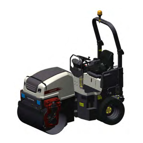
Introduction Introduction The machine Dynapac CC1100C VI /1200C VI are two vibratory combination rollers in the 2.5-ton class with 1070/1200 mm wide drums and a wheel width of 1050/1180 mm. The drum can be used with vibration and both drum and wheels are driven and fitted with brakes. -
Page 16: General
Introduction Read the entire manual before starting the Read the entire manual before starting the machine and before carrying out any machine and before carrying out any maintenance. maintenance. Replace immediately the instruction manuals if Replace immediately the instruction manuals if lost, damaged or unreadable. -
Page 17: Ce Marking And Declaration Of Conformity
Introduction THINK ENVIRONMENT ! Do not release oil, THINK ENVIRONMENT ! Do not release oil, fuel and other environmentally hazardous fuel and other environmentally hazardous substances into the environment. Always send substances into the environment. Always send used filters, drain oil and fuel remnants to used filters, drain oil and fuel remnants to environmentally correct disposal. - Page 18 Introduction 4812163101_A.pdf 2018-12-14...
-
Page 19: Safety - General Instructions
Safety - General instructions Safety - General instructions (Also read the safety manual) The operator must be familiar with the contents of the OPERATION section The operator must be familiar with the contents of the OPERATION section before starting the roller. before starting the roller. - Page 20 Safety - General instructions 16. Hearing protection is recommended if the noise level exceeds 80 dB(A). The 16. Hearing protection is recommended if the noise level exceeds 80 dB(A). The noise level can vary depending on the equipment on the machine and the noise level can vary depending on the equipment on the machine and the surface the machine is being used on.
-
Page 21: Safety - When Operating
Safety - when operating Safety - when operating Prevent persons from entering or remaining in Prevent persons from entering or remaining in the danger area, i.e. a distance of at least 7 m the danger area, i.e. a distance of at least 7 m (23 ft) in all directions from operating machines. -
Page 22: Driving Near Edges
Safety - when operating Driving near edges Never operate with roller outside the edge, if the Never operate with roller outside the edge, if the substrate does not have full bearing strength or is substrate does not have full bearing strength or is close to a slope. -
Page 23: Safety (Optional)
Safety (Optional) Safety (Optional) Edge cutter/compactor The operator must make sure that nobody is in the The operator must make sure that nobody is in the area of operation while the machine is in use. area of operation while the machine is in use. The edge cutter consists of rotating components The edge cutter consists of rotating components and there is a risk of being crushed. - Page 24 Safety (Optional) Fitting the chip spreader changes the total length Fitting the chip spreader changes the total length of the machine. of the machine. 4812163101_A.pdf 2018-12-14...
-
Page 25: Special Instructions
Special instructions Special instructions Standard lubricants and other recommended oils and fluids Before leaving the factory, the systems and components are filled with the oils and fluids specified in the lubricant specification. These are suitable for ambient temperatures in the range -15°C to +40°C (5°F - 105°F). -
Page 26: Fire Fighting
Special instructions Do not spray with high-pressure cleaner directly onto gaskets and bearing spacings in steering hitch and drum, and electronics. Never aim the water jet directly at the fuel tank Never aim the water jet directly at the fuel tank cap, or into exhaust pipe. -
Page 27: Jump Starting
Special instructions Jump starting Do not connect the negative cable to the Do not connect the negative cable to the negative terminal on the dead battery. A spark negative terminal on the dead battery. A spark can ignite the oxy-hydrogen gas formed can ignite the oxy-hydrogen gas formed around the battery. - Page 28 Special instructions 4812163101_A.pdf 2018-12-14...
-
Page 29: Technical Specifications
Technical specifications Technical specifications Vibrations - Operator station (ISO 2631) The vibration levels are measured in accordance with the operational cycle described in The vibration levels are measured in accordance with the operational cycle described in EU directive 2000/14/EC on machines equipped for the EU market, with vibration switched EU directive 2000/14/EC on machines equipped for the EU market, with vibration switched on, on soft polymer material and with the operator’s seat in the transport position. -
Page 30: Dimensions, Top View
Technical specifications Dimensions, top view Dimensions Dimensions Machine width Machine width CC1100C VI CC1100C VI 1210 1210 CC1200C VI CC1200C VI 1340 1340 B (without ROPS) B (without ROPS) Machine width Machine width CC1100C VI CC1100C VI 1210 1210 CC1200C VI CC1200C VI 1340 1340... -
Page 31: Dimensions, Side View
Technical specifications Dimensions, side view Dimensions Dimensions Wheel base Wheel base 1700 1700 Diameter, drum Diameter, drum Height, with ROPS Height, with ROPS 2542 2542 Height, without ROPS Height, without ROPS 1744 1744 68.5 68.5 Length Length 2375 2375 93.5 93.5 Length, with chip spreader Length, with chip spreader... -
Page 32: Weights And Volumes
Technical specifications Weights and volumes Fluid volumes Fluid volumes Fuel tank Fuel tank 45 liters 45 liters 47.6 qts 47.6 qts Water tank Water tank 183 liters 183 liters 193.4 qts 193.4 qts Emulsion tank Emulsion tank 20 liters 20 liters 21.1 qts 21.1 qts Weights... -
Page 33: General
Technical specifications Propulsion Propulsion Speed range Speed range 0-10 0-10 km/h km/h 0-6.2 0-6.2 Climbing capacity (theoretical) Climbing capacity (theoretical) CC1100C VI CC1100C VI up to 71* up to 71* CC1200C VI CC1200C VI up to 65* up to 65* *) depending on model, diesel engine, other equipment and operating conditions. -
Page 34: Tightening Torque
Technical specifications Tightening torque Tightening torque in Nm for oiled or dry bolts tightened with a torque wrench. Metric coarse screw thread, bright galvanized (fzb): STRENGTH CLASS: 8.8, Oiled 8.8, Oiled 8.8, Dry 8.8, Dry 10.9, Oiled 10.9, Oiled 10.9, Dry 10.9, Dry 12.9, Oiled 12.9, Oiled... -
Page 35: Rops - Bolts
Technical specifications ROPS-bolts which are to be torque tightened ROPS-bolts which are to be torque tightened must be dry. must be dry. ROPS - bolts Bolt dimensions : Bolt dimensions : M16 (PN 4700902889) M16 (PN 4700902889) Strength class : Strength class : Tightening torque : Tightening torque :... - Page 36 Technical specifications 4812163101_A.pdf 2018-12-14...
-
Page 37: Machine Description
Machine description Machine description Diesel engine The machine is equipped with a water-cooled, straight three cylinder, four-stroke, diesel engine. Electrical system The machine has the following control units (ECU, Electronic Control Unit) and electronic units. • Main ECU (for the machine) •... -
Page 38: Identification
Machine description modification with Dynapac's production unit. Dynapac determines whether the modification could result in the approval according to the ROPS standards becoming invalid. Identification Product and component plates Product plate - Product Identification Number (PIN), model/type designation Product plate - Product Identification Number (PIN), model/type designation Engine plate - Type description, product and serial numbers Engine plate - Type description, product and serial numbers ROPS plate - Certification, product and serial numbers... -
Page 39: Explanation Of 17Pin Serial Number
Machine description Explanation of 17PIN serial number A= Manufacturer 00123 00123 123456 123456 B= Family/Model C= Check letter F= Serial number Machine plate The machine type plate (1) is affixed on the rear left edge of the frame. The plate specifies the manufacturer's name and address, the type of machine, the PIN number (serial number), service weight, engine power and year of manufacture. -
Page 40: Engine Plates
Machine description Engine plates The engine's type plate (1) is located on top of the cylinder head cover. The plate specifies the type of engine, its serial number and the engine specification. Please specify the engine serial number when ordering spares. Refer also to the engine manual. Fig. - Page 41 Machine description 2018-12-14 4812163101_A.pdf...
-
Page 42: Location - Decals
Machine description Location - decals 6, 21 Fig. Location, decals and signs Warning, Crush zone Warning, Crush zone 4700903422 4700903422 Hydraulic fluid level Hydraulic fluid level 4700272373 4700272373 Warning, Rotating engine Warning, Rotating engine 4700903423 4700903423 Warning, Starting gas Warning, Starting gas 4700791642 4700791642 components... - Page 43 Machine description 2018-12-14 4812163101_A.pdf...
- Page 44 Machine description Location - decals 6, 21 Fig. Location, decals and signs Warning, Crush zone Warning, Crush zone 4700903422 4700903422 Hydraulic fluid level Hydraulic fluid level 4700272373 4700272373 Warning, Rotating engine Warning, Rotating engine 4700903423 4700903423 Warning, Starting gas Warning, Starting gas 4700791642 4700791642 components...
-
Page 45: Safety Decals
Machine description Safety decals Always make sure that all safety decals are completely legible, and remove dirt or order new decals if they have become illegible. Use the part number specified on each decal. 4700903422 Warning - Crush zone, articulation/drum. Maintain a safe distance from the crush zone. - Page 46 Machine description 4700903422 Warning - Crush zone, chip spreader (optional) Risk of personal injury or being crushed. Keep well clear of the spreader's working area 4700908229 Warning - Risk of crushing The articulation must be locked when lifting. Read the instruction manual. 4812125363 Warning - Locking The articulation must be locked during transport...
- Page 47 Machine description 4812129673 Warning CALIFORNIA - Proposition 65 2018-12-14 4812163101_A.pdf...
-
Page 48: Info Decals
Machine description Info decals Noise power level Noise power level Diesel fuel Diesel fuel Lifting point Lifting point Manual compartment Manual compartment Battery disconnector Battery disconnector Fixing point Fixing point Bio hydraulic fluid, PANOLIN Hydraulic fluid level Bio hydraulic fluid, PANOLIN Hydraulic fluid level Water Water Air pressure... -
Page 49: Instruments/Controls
Machine description Instruments/Controls Locations - Control panel and controls Fig. Operator's Fig. Operator position station Ignition key Ignition key Fuse holder Fuse holder Direction selector / Direction selector / indicator indicator Engine speed control Engine speed control Instrument cover Instrument cover Emergency stop Emergency stop (D1703) -
Page 50: Functional Description - Membrane Panel
Machine description Functional description - Membrane panel Working mode Vibration, high/low amplitude Rotating beacon Working lights Sprinkler timer Sprinkler, manual / automatic Engine speed selector Horn (D1803) Function description - Display Designation Designation Function Function Vibration ON/OFF Vibration ON/OFF When button 1 and/or button 2 are pressed in and Working mode/Vibration is When button 1 and/or button 2 are pressed in and Working mode/Vibration is activated, vibrations are enabled. - Page 51 Machine description Designation Function Designation Function color color Working Working Activates working mode, which makes it possible to use vibration and edge Activates working mode, which makes it possible to use vibration and edge mode mode cutter (optional). cutter (optional). (vibration and (vibration and LED OFF = Transport mode...
-
Page 52: Display Explanations
Machine description Designation Function Designation Function color color Horn, switch Horn, switch Press to sound the horn. Press to sound the horn. Engine speed Engine speed Only activated for electronic controlled engine speed (D1803) Only activated for electronic controlled engine speed (D1803) selector selector LED LEFT = Low speed... -
Page 53: Transport Mode
Machine description Transport mode The transport mode screen provides information about travel direction (2), machine hours (3) and fuel level (4). 2. Direction of travel - The icon has three options (F, N, R) and is shown in the top left of the display. Only current status is displayed. -
Page 54: Working Mode, Vibration
Machine description Working mode, Vibration The different working modes are selected with the help of the working mode button on the panel. 2. Direction of travel - The icon has three options (F, N, R) and is clearly visible in the top left of the display. Only one can be selected. - Page 55 Machine description Machine with dual controls (option). Standard equipped machine. Fig. Forward/Reverse lever right Fig. Double forward/reverse lever 1. Vibration on/off 1. Vibration on/off, front drum 2. Vibration on/off, rear drum 2018-12-14 4812163101_A.pdf...
-
Page 56: Working Mode - Edge Cutter
Machine description Working mode - Edge cutter The different working modes are selected with the help of the working mode button on the panel. 2. Direction of travel - The icon has three options (F, N, R) and is shown in the top left of the display. -
Page 57: Working Mode - Chip Spreader
Machine description Working mode - Chip spreader The different working modes are selected with the help of the button on the panel. 2. Direction of travel - The icon has three options (F, N, R) and is shown in the top left of the display. - N (Neutral) shows that the control lever is in the neutral position and no arrow is shown on the display. -
Page 58: Function Description, Buttons On From/Rear Control
Machine description Function description, buttons on from/rear control Left lever (LH) Right lever (RH) Mode / Button Mode / Button Button 1 Button 1 Button 2 Button 2 Button 3 Button 3 Transport mode Transport mode None None None None Edge cutter, up Edge cutter, up Working mode... -
Page 59: User Settings
Machine description User settings Users can change the light settings (10), choose between the Metric or Imperial system (11), and set warning sounds on/off (12). Fig. User settings 10. Light settings 11. Metric / Imperial unit Fig. User settings 12. Sound setting 13. -
Page 60: Sub-Menu - Regeneration (Only D1803 T4F (28 Kw))
Machine description Sub-menu - Regeneration (only D1803 T4f (28 kW)) The menu is accessed from the active Home mode. 1. Regeneration is possible to perform when the symbol (1) lights. - The side menu is displayed, when the sub-menu is selected. - Page 61 Machine description 3. Now go to the User settings sub-menu. 4. The middle button (4) on the side menu shows a downward arrow. When this is selected, an error code list appears. When the last error code is shown, scroll the list up to the first error code again.
-
Page 62: Function Description - Alarm
Machine description Function description - Alarm No Symbol Designation and Function No Symbol Designation and Function Warning lamp (Red) Warning lamp (Red) Serious fault: Switch off engine Serious fault: Switch off engine immediately! immediately! Launched together with a message on Launched together with a message on the display. -
Page 63: Electrical System
Machine description Electrical system Fuses The figure shows the position of the fuses. The table below gives fuse amperage and function. All fuses are flat pin fuses. Fig. Fuse box Fuse box Fuse box 1. F1 1. F1 Sprinkler Sprinkler 2. -
Page 64: Fuses At Battery Master Disconnect Switch
Machine description Fuses at battery master disconnect switch The figure shows the different positions of the fuses in the engine compartment. The table below gives fuse amperage and function. All fuses are flat pin fuses. D1703 Main fuse Main fuse Glowing, Start relay, Fuel Glowing, Start relay, Fuel solenoid... -
Page 65: Relays On Machine
Machine description Relays on machine Engine compartment (D1703) Starting Starting Fuel solenoid Fuel solenoid Glowing / Preheater Glowing / Preheater Fig. Relays Engine compartment (D1703) Engine compartment (D1803) Start relay Start relay Engine ECU relay Engine ECU relay Glowing relay Glowing relay Fig. - Page 66 Machine description Steering column K6.1 K6.1 Working lights frame Working lights frame K6.2 K6.2 Working lights ROPS or Water Working lights ROPS or Water tank tank Driving lights Driving lights Driving lights, direction indicator Driving lights, direction indicator K12.1 K12.1 Sprinkler Sprinkler K12.2...
-
Page 67: Operation
Operation Operation Before starting Master switch - Switching on Remember to carry out daily maintenance. See the maintenance instructions. The battery disconnector is on the left side in the engine compartment. Turn the key (1) to switched on position. The roller is now supplied with power. -
Page 68: Driver Seat - Adjustment
Operation Driver seat - Adjustment Adjust the operator’s seat so that the position is comfortable and so that the controls are within easy reach. The tables below show the adjustments that can be made on the different seats. The image below to the left shows a fully equipped luxury comfort seat while the image below to the right shows a normally equipped comfort seat. -
Page 69: Parking Brake - Check
Operation Fig. Driver seat (MSG65) 5. Lumbar support adjustment 6. Backrest extension 7. Armrest, adjustable 8. Seat heating Lumbar support Lumbar support Backrest Backrest Armrest, Armrest, Seat heating (8) Seat heating (8) adjustment (5) adjustment (5) extension (6) extension (6) adjustable (7) adjustable (7) Standard seat... -
Page 70: Reserve Brake - Control
Operation The engine can only be started with the parking The engine can only be started with the parking brake (6) activated. brake (6) activated. Reserve brake - Control Drive slowly fowards/backwards and press down the parking brake button (6) to activate it. The roller must now stop immediately. -
Page 71: Interlock
Operation Interlock The roller is equipped with Interlock. The diesel engine with switch off after 4 seconds if the operator gets off the seat when going forwards/backwards. If the control is in neutral when the operator stands up a buzzer will go on until the parking brake button is activated. -
Page 72: Operator Position
Operation Operator position If a ROPS (Roll Over Protective Structure) is fitted to the roller, always wear the seat belt (1) and wear a protective helmet. Always replace the seat belt (1) if it shows signs of Always replace the seat belt (1) if it shows signs of wear or has been subjected to excessive strain. -
Page 73: Flow Divider (Optional)
Operation Flow divider (Optional) The switch on the floor (to the left) must be press down to activate the flow divider. The flow divider is enabled as long as the switch is actuated. Remove your foot from the switch to disable the flow divider. -
Page 74: D1803
Operation D1803 Make sure that the LED button (32) is set to LOW mode (1 lamp lit). Warm up the engine at idling speed for a few minutes, although longer if ambient temperature is below +10°C (50°F). If the parking brake is not activated and the If the parking brake is not activated and the forward/reverse lever is in neutral, the parking forward/reverse lever is in neutral, the parking... -
Page 75: Driving
Operation Driving Operating the roller Under no circumstances is the machine to be Under no circumstances is the machine to be operated from the ground. The operator must be operated from the ground. The operator must be seated inside the machine during all operation. seated inside the machine during all operation. -
Page 76: Interlock/Emergency Stop/Parking Brake - Check
Operation Interlock/Emergency stop/Parking brake - Check The interlock, emergency stop and parking brake must The interlock, emergency stop and parking brake must be checked daily before operating. A function check of be checked daily before operating. A function check of the interlock and emergency stop requires a restart. -
Page 77: Edge Cutting (Optional)
Operation Edge cutting (Optional) The machine must be running to activate the edge cutter/compactor. With the machine in Working mode/Edge cutter (20) (middle LEDs lit) the edge cutter/compactor is controlled up and down with the help of button (3) and button (2) on the control lever. -
Page 78: Vibration
Operation Vibration Manual/Automatic vibration In Working mode/Vibration (20) (LED LEFT lit) you can select, manually, which drum is to vibrate with the button on the forward/reverse lever. For Standard machine: Button (1) activates vibration on on both the drums. For machines equipped with options: Button (1) activates vibration on the front drum. -
Page 79: Braking
Operation Braking Normal braking Turn off the vibration using the buttons (1) and (2) on the control lever. Move the forward/reverse lever (6) to the neutral position to stop the roller. When starting and driving a machine that is cold, When starting and driving a machine that is cold, remember that the hydraulic fluid is also cold and remember that the hydraulic fluid is also cold and... -
Page 80: Switching Off
Operation Switching off Activate the parking brake (31). D1703 Turn the engine speed control (2) back to idling. D1803 Press the LED button (32) so it is set to LOW mode (left LED lit). Fig. Instrument panel Allow the engine to idle for a few minutes to cool down. 1. -
Page 81: Parking
Operation Parking Chocking the wheels/drum Never disembark from the machine when the is Never disembark from the machine when the is engine running, unless the parking brake is engine running, unless the parking brake is activated. activated. Make sure that the roller is parked in a safe place Make sure that the roller is parked in a safe place with respect to other road users. - Page 82 Operation 4812163101_A.pdf 2018-12-14...
-
Page 83: Long-Term Parking
Long-term parking Long-term parking The following instructions should be followed The following instructions should be followed when long term parking (more than one month). when long term parking (more than one month). These measures apply when parking for a period of up to 6 months. -
Page 84: Steering Cylinder, Hinges, Etc
Long-term parking Steering cylinder, hinges, etc. Lubricate the steering joint bearings and the steering cylinder's two bearings with grease. Grease the piston rod of the steering cylinder with inhibitor grease. Grease the hinges on the engine compartment hood and also grease both ends of the forward/reverse control (bright parts). -
Page 85: Miscellaneous
Miscellaneous Miscellaneous Lifting Locking the articulation Articulation must be locked to prevent inadvertent Articulation must be locked to prevent inadvertent turning before lifting the roller. turning before lifting the roller. Turn the steering wheel to the straight ahead position. Enable the parking brake. Pull out the locking pin (2) fitted with a wire, and pull up/out the locking dowel (3). -
Page 86: Lifting The Roller
Miscellaneous Weight: see the machine plate on the roller Lifting the roller The maximum weight of the machine (5) can be The maximum weight of the machine (5) can be read on the machine plate (1). read on the machine plate (1). Lifting equipment such as chains, steel wires, Lifting equipment such as chains, steel wires, straps and lifting hooks must be dimensioned in... -
Page 87: Lifting The Roller With A Single -Point Lift (Optional)
Miscellaneous Lifting the roller with a single -point lift (Optional) The maximum weight of the machine (5) can be The maximum weight of the machine (5) can be read on the machine plate (1). read on the machine plate (1). Lifting equipment such as chains, steel wires, Lifting equipment such as chains, steel wires, straps and lifting hooks must be dimensioned in... -
Page 88: Unlocking The Articulation
Miscellaneous Unlocking the articulation Remember to unlock the articulation before Remember to unlock the articulation before operating. operating. Fold the locking arm (3) back and secure it in the locking lug (4) with the stud (3). Insert the locking pin (2) fitted with a wire, to secure the stud (3). -
Page 89: Release The Brakes
Miscellaneous Release the brakes Activate the parking brake, and stop the engine. Activate the parking brake, and stop the engine. Block the drum with a chock to prevent movement; Block the drum with a chock to prevent movement; the roller can start rolling when the brakes are the roller can start rolling when the brakes are released. -
Page 90: Releasing The Brake, Wheel Motors (Optional)
Miscellaneous Releasing the brake, wheel motors (Optional) Activate the parking brake, and stop the engine. Activate the parking brake, and stop the engine. Block the drum with a chock to prevent movement; Block the drum with a chock to prevent movement; the roller can start rolling when the brakes are the roller can start rolling when the brakes are released. -
Page 91: Short Distance Towing With Switched Off Engine
Miscellaneous Short distance towing with switched off engine Chock the drums to prevent the roller from Chock the drums to prevent the roller from moving. moving. Open the hood and make sure that the propulsion pump is accessible. There is a bypass screw (1) located on the pump that must be unscrewed counterclockwise (max two turns), to put the drive system (ports A and B) in bypass mode. -
Page 92: Towing The Roller
Miscellaneous Towing the roller The roller must be counter-braked during The roller must be counter-braked during towing/recovery. Always use a towbar. There is no towing/recovery. Always use a towbar. There is no braking capacity on the roller now. braking capacity on the roller now. The roller must be towed slowly, max. -
Page 93: Transport
Miscellaneous Transport Tie-down and secure the machine according to the Cargo Securing Certificate for the specific machine if this is avaliable and applicable. If not, tie down and secure the machine according to the cargo securing rules that are valid for the country where the transport takes place. -
Page 94: Securing Cc1100C Vi / 1200C Vi For Loading
Miscellaneous Securing CC1100C VI / 1200C VI for loading Securing the CC1100C VI / 1200C VI vibratory roller from Dynapac for transport. Roller loaded in forward direction Direct of travel 1 - 2 = double lashings, i.e. one lashing with two parts secured to two different lashing mounts on 1 - 2 = double lashings, i.e. - Page 95 Miscellaneous The contact surfaces must be clean, wet or dry, and free from frost, ice and snow. The contact surfaces must be clean, wet or dry, and free from frost, ice and snow. The lashing mounts on the load carrier have LC/MSL at least 2 tonnes. The lashing mounts on the load carrier have LC/MSL at least 2 tonnes.
-
Page 96: Securing Cc1100C Vi / 1200C Vi For Loading (Side Across The Trailer)
Miscellaneous Securing CC1100C VI / 1200C VI for loading (Side across the trailer) Securing the CC1100C VI / 1200C VI vibratory roller from Dynapac for transport. Roller loaded in forward direction Direct of travel = two sling straps, one directed to the right and one to the left, which are attached on the = two sling straps, one directed to the right and one to the left, which are attached on the platform as close to the rollers as possible. - Page 97 Miscellaneous Load carrier Load carrier Ensure that: Ensure that: When loaded, the vibratory roller is centered laterally on the platform (± 5 cm). When loaded, the vibratory roller is centered laterally on the platform (± 5 cm). The parking brake is applied and in good working condition, and the articulated joint lock is The parking brake is applied and in good working condition, and the articulated joint lock is closed.
-
Page 98: Securing Cc1100C Vi / 1200C Vi For Loading (Side Along The Trailer)
Miscellaneous Securing CC1100C VI / 1200C VI for loading (Side along the trailer) Securing the CC1100C VI / 1200C VI vibratory roller from Dynapac for transport. Roller loaded in forward direction Direct of travel 1 - 2 = double lashings, i.e. one lashing with two parts secured to two different lashing mounts on 1 - 2 = double lashings, i.e. - Page 99 Miscellaneous Load carrier Load carrier Ensure that: Ensure that: When loaded, the vibratory roller is centered laterally on the platform (± 5 cm). When loaded, the vibratory roller is centered laterally on the platform (± 5 cm). The parking brake is applied and in good working condition, and the articulated joint lock is The parking brake is applied and in good working condition, and the articulated joint lock is closed.
-
Page 100: Foldable Rops
Miscellaneous Foldable ROPS The machine is equipped with foldable ROPS Risk of crush injury when raising and lowering Risk of crush injury when raising and lowering ROPS. ROPS. Always make sure the ROPS is locked in raised Always make sure the ROPS is locked in raised position before operation position before operation Fig. -
Page 101: Operating Instructions - Summary
Operating instructions - Summary Operating instructions - Summary Follow the SAFETY INSTRUCTIONS specified in the Safety Manual. Follow the SAFETY INSTRUCTIONS specified in the Safety Manual. Make sure that all instructions in the MAINTENANCE section are followed. Make sure that all instructions in the MAINTENANCE section are followed. Turn the master switch to the ON position. - Page 102 Operating instructions - Summary 4812163101_A.pdf 2018-12-14...
-
Page 103: Preventive Maintenance
Preventive maintenance Preventive maintenance Complete maintenance is necessary for the machine to function satisfactorily and at the lowest possible cost. The Maintenance section includes the periodic maintenance that must be carried out on the machine. The recommended maintenance intervals assume that the machine is used in a normal environment and working conditions. - Page 104 Preventive maintenance 4812163101_A.pdf 2018-12-14...
-
Page 105: Maintenance - Lubricants And Symbols
Maintenance - Lubricants and symbols Maintenance - Lubricants and symbols Always use high-quality lubricants and the Always use high-quality lubricants and the amounts recommended. Too much grease or amounts recommended. Too much grease or oil can cause overheating, resulting in rapid oil can cause overheating, resulting in rapid wear. - Page 106 Maintenance - Lubricants and symbols ENGINE OIL ENGINE OIL Air temperature -15°C - +50°C Air temperature -15°C - +50°C Dynapac Engine Oil Dynapac Engine Oil P/N 4812161855 (5 liter) P/N 4812161855 (5 liter) (5°F-122°F) (5°F-122°F) P/N 4812161856 (20 liter) P/N 4812161856 (20 liter) P/N 4812161857 (209 liter) P/N 4812161857 (209 liter) HYDRAULIC FLUID...
-
Page 107: Maintenance Symbols
Maintenance - Lubricants and symbols Maintenance symbols Engine, oil level Engine, oil level Air filter Air filter Engine, oil filter Engine, oil filter Battery Battery Hydraulic reservoir, level Hydraulic reservoir, level Sprinkler Sprinkler Hydraulic fluid, filter Hydraulic fluid, filter Sprinkler water Sprinkler water Drum, oil level Drum, oil level... - Page 108 Maintenance - Lubricants and symbols 4812163101_A.pdf 2018-12-14...
-
Page 109: Maintenance - Maintenance Schedule
Maintenance - Maintenance schedule Maintenance - Maintenance schedule Service and maintenance points Fig. Service and maintenance points Fuel tank Fuel tank Sprinkler system/Drum Sprinkler system/Drum Steering joint Steering joint Refueling Refueling Scrapers/Drum Scrapers/Drum Steering cylinder, bearings Steering cylinder, bearings Cooler Cooler 10. -
Page 110: General
Maintenance - Maintenance schedule General Periodic maintenance should be carried out after the number of hours specified. Use the daily, weekly etc. periods where number of hours cannot be used. Remove all dirt before filling, when checking Remove all dirt before filling, when checking oils and fuel and when lubricating using oil or oils and fuel and when lubricating using oil or grease. -
Page 111: After The First 50 Hours Of Operation
Maintenance - Maintenance schedule After the FIRST 50 hours of operation See Contents to find the page number of the sections referred to! Pos. Pos. Action Action Comment Comment in fig in fig Change the engine oil and oil filter Change the engine oil and oil filter Refer to the engine manual Refer to the engine manual... -
Page 112: Every 500 Hours Of Operation
Maintenance - Maintenance schedule Every 500 hours of operation See Contents to find the page number of the sections referred to! Pos. Pos. Action Action Comment Comment in fig in fig Check the condition of the battery Check the condition of the battery Change engine oil and oil filter Change engine oil and oil filter Refer to the engine manual... -
Page 113: Every 1000 Hours Of Operation
Maintenance - Maintenance schedule Every 1000 hours of operation See Contents to find the page number of the sections referred to! Pos. Pos. Action Action Comment Comment in fig in fig Check the condition of the battery Check the condition of the battery Change engine oil and oil filter Change engine oil and oil filter Refer to the engine manual... -
Page 114: Every 2000 Hours Of Operation
Maintenance - Maintenance schedule Every 2000 hours of operation See Contents to find the page numbers of the sections referred to! Pos. Pos. Action Action Comment Comment in fig in fig Check the battery condition Check the battery condition Change the engine oil and oil filter Change the engine oil and oil filter Refer to the engine manual Refer to the engine manual... -
Page 115: Every 3000 Hours Of Operation
Maintenance - Maintenance schedule Every 3000 hours of operation See Contents to find the page numbers of the sections referred to! Pos. Pos. Action Action Comment Comment in fig in fig Check the battery condition Check the battery condition Change the engine oil and oil filter Change the engine oil and oil filter Refer to the engine manual Refer to the engine manual... -
Page 116: Every 12Th Month (Annually)
Maintenance - Maintenance schedule Every 12th month (Annually) Refer to the contents to find the page number of the sections referred to ! Pos. Pos. Action Action Comment Comment in fig in fig Replacing the air filters (main and backup filter) Replacing the air filters (main and backup filter) Check the DPF pipes and connections Check the DPF pipes and connections... -
Page 117: Service - Checklist
Maintenance - Maintenance schedule Service - Checklist 2018-12-14 4812163101_A.pdf... - Page 118 Maintenance - Maintenance schedule 4812163101_A.pdf 2018-12-14...
-
Page 119: Maintenance, 10H
Maintenance, 10h Maintenance, 10h Every 10 hours of operation (Daily) Park the roller on a level surface. Park the roller on a level surface. The engine must be switched off and the The engine must be switched off and the parking brake activated when checking or parking brake activated when checking or adjusting the roller, unless otherwise specified. -
Page 120: Diesel Engine Check Oil Level
Maintenance, 10h Diesel engine Check oil level Ensure that the engine cover is fully open when Ensure that the engine cover is fully open when work is carried out under the cover. work is carried out under the cover. Open the engine cover lock and lower the engine cover forwards. -
Page 121: Hydraulic Reservoir, Level Check - Filling
Maintenance, 10h Hydraulic reservoir, Level check - Filling Check that the oil level is visible in the sight glass. Open the engine hood and unscrew the filler cap (2), top up with hydraulic fluid (as per lubricant specification) if the level is too low. Screw on the cap again after filling. -
Page 122: Fuel Tank - Filling
Maintenance, 10h Fuel tank - Filling Refuel the tank every day before starting work. Open the engine hood, unscrew the tank cap (1) fill with diesel up to the lower edge of the filler pipe. T4F/Stage IV Kubota engines require the use of T4F/Stage IV Kubota engines require the use of Ultra Low Sulphur Diesel (ULSD) fuel, which has Ultra Low Sulphur Diesel (ULSD) fuel, which has... -
Page 123: Sprinkler System/Drum Checking - Cleaning
Maintenance, 10h Sprinkler system/Drum Checking - Cleaning Start the sprinkler system and make sure that no nozzles (1) are clogged. If necessary, clean clogged nozzles and the coarse filter located by the water pump; see figures below. The sprinkler system The sprinkler system should be drained if there should be drained if there... -
Page 124: Pump System / Tire Check - Cleaning
Maintenance, 10h When cleaning the coarse filter (1), open the cock (2) and loosen the filter housing. Clean the filter and filter housing. Check that the rubber gasket in the filter housing is intact. After inspecting and carrying out any necessary cleaning, start the system and check that it works. -
Page 125: Sprinkler System/Drum Cleaning Of Sprinkler Nozzle
Maintenance, 10h Sprinkler system/Drum Cleaning of sprinkler nozzle Dismantle the blocked nozzle by hand. Blow the nozzle (1) and fine filter (3) clean using compressed air. Alternatively, fit replacement parts and clean the blocked parts later on. Nozzle Nozzle Colour Colour l/min (at 2.0 l/min (at 2.0... -
Page 126: Scrapers, Spring-Action (Optional) Checking - Adjustment
Maintenance, 10h Scrapers, spring-action (Optional) Checking - Adjustment The scrapers must be lifted from the drum during The scrapers must be lifted from the drum during transport. transport. Fig. Spring-action scrapers 1. Scraper blade 2. Adjusting screws 3. Springs Scrapers Check - Adjustment Make sure that the scraper (1) is flush with the tire when compacting asphalt. -
Page 127: Brakes - Check
Maintenance, 10h Brakes - Check Check operation of the brakes as follows: Check operation of the brakes as follows: Run the roller very slowly forward. Hold the steering wheel firmly and brace yourself for a sudden stop. Make sure the parking brake is deactivated and press Figure. - Page 128 Maintenance, 10h 4812163101_A.pdf 2018-12-14...
-
Page 129: Maintenance Measures, First 50 Hours
Maintenance measures, First 50 hours Maintenance measures, First 50 hours Park the roller on a level surface. Park the roller on a level surface. The engine must be switched off and the The engine must be switched off and the parking brake activated when checking or parking brake activated when checking or adjusting the roller, unless otherwise specified. - Page 130 Maintenance measures, First 50 hours Set a container which can hold at least 8 liters (2 gal) under the drain plug (2). Undo the oil filler cap (3), and undo the drain plug (2) in the end of the drain hose (1). Let all the engine oil flow out.
-
Page 131: Replacing The Hydraulic Oil Filter
Maintenance measures, First 50 hours Replacing the hydraulic oil filter Open the engine hood. Loosen the red cap (1) and pull up the filter insert (4). Refit the red cap temporarily to prevent dust and dirt getting into the tank. Fig. -
Page 132: Bolted Joints Check
Maintenance measures, First 50 hours Bolted joints Check Check that all bolted joints (1) are tightened correctly. Fig. Drum forks Fig. Articulated joint 1. Bolted joints 1. Bolted joints 4812163101_A.pdf 2018-12-14... -
Page 133: Maintenance - 50H
Maintenance - 50h Maintenance - 50h Every 50 hours of operation (Weekly) Park the roller on a level surface. Park the roller on a level surface. The engine must be switched off and the The engine must be switched off and the parking brake activated when checking or parking brake activated when checking or adjusting the roller, unless otherwise specified. -
Page 134: Steering Cylinder And Steering Joint - Lubrication
Maintenance - 50h Steering cylinder and steering joint - Lubrication Do not allow anyone to remain in the vicinity of the Do not allow anyone to remain in the vicinity of the steering joint when the engine is running. Danger steering joint when the engine is running. -
Page 135: Checking The Fuel Hoses And Hose Clamps
Maintenance - 50h Checking the fuel hoses and hose clamps Stop the engine before checking or replacing the Stop the engine before checking or replacing the fuel pipes. Defective fuel pipes can cause a fire. fuel pipes. Defective fuel pipes can cause a fire. If the fuel pipes are not connected, plug them at If the fuel pipes are not connected, plug them at both ends with a clean cloth or paper to prevent dirt... -
Page 136: Water Separator - Draining (On Machines Equipped With This)
Maintenance - 50h Water separator - Draining (on machines equipped with this) If water or contaminates accumulate in the water separator, an indication will be shown on the display. If this should happen during operation, drain from the draining plug. (1). Fig. -
Page 137: Maintenance Measures - 250 H
Maintenance measures - 250 h Maintenance measures - 250 h Every 250/750/1250/1750..hours of operation (every 3 months) Park the roller on a level surface. Park the roller on a level surface. The engine must be switched off and the The engine must be switched off and the parking brake activated when checking or parking brake activated when checking or... -
Page 138: Engine Oil And Oil Filter - Change
Maintenance measures - 250 h Engine oil and oil filter - Change Run the engine until it is warm before draining the oil . Switch off the engine and push in the emergency Switch off the engine and push in the emergency stop. -
Page 139: Air Cleaner - Cleaning
Maintenance measures - 250 h Remove the oil filter (4). Collect any spillage. Install the new filter. Fit the drain plug (2) to the end of the hose. Fill with fresh engine oil. See under the heading lubricants, for the correct oil grade. Fit the filler cap (3) and check that the oil level is correct using the dipstick. -
Page 140: Replacing Belts/Checking The Belt Tension
Maintenance measures - 250 h Replacing belts/Checking the belt tension Exercise care to stop the engine and remove the Exercise care to stop the engine and remove the key before checking the belt tension. key before checking the belt tension. Exercise care to install the standalone safety Exercise care to install the standalone safety shield after maintenance or inspection. -
Page 141: Check - Coolant System
Maintenance measures - 250 h Check - Coolant system Check that all hoses/hose connectors are intact and tight. Fill with coolant as specified in the lubricants specification. Take great care when opening the radiator cap Take great care when opening the radiator cap while the engine is hot. -
Page 142: Check - Air Intake Hoses
Maintenance measures - 250 h Check - Air intake hoses Check that all hoses/hose connections are intact and tight. Fig. Engine compartment - D1703-M-DI-E4B (T4f) 1. Air intake hoses Fig. Engine compartment - Fig. Engine compartment - D1803 CR D1703-M-IDI-E3 (T3) (T4f) 1. -
Page 143: Maintenance - 500H
Maintenance - 500h Maintenance - 500h Park the roller on a level surface. Park the roller on a level surface. The engine must be switched off and the The engine must be switched off and the parking brake activated when checking or parking brake activated when checking or adjusting the roller, unless otherwise specified. -
Page 144: Engine Oil And Oil Filter - Change
Maintenance - 500h Engine oil and oil filter - Change Run the engine until it is warm before draining the oil . Switch off the engine and push in the emergency Switch off the engine and push in the emergency stop. -
Page 145: Drum - Oil Level Inspection - Filling
Maintenance - 500h Remove the oil filter (4). Collect any spillage. Install the new filter. Fit the drain plug (2) to the end of the hose. Fill with fresh engine oil. See under the heading lubricants, for the correct oil grade. Fit the filler cap (3) and check that the oil level is correct using the dipstick. -
Page 146: Rubber Elements And Bolted Joints Check
Maintenance - 500h Rubber elements and bolted joints Check Check all rubber elements (1). Replace all elements where more than 25% of the elements on one side of the drum have cracks deeper than 10-15 mm (0.4-0.6 in). Check using a knife blade or pointed object. Check also that the attachment screws (2) are tightened. -
Page 147: Steering Cylinder And Steering Joint - Lubrication
Maintenance - 500h Steering cylinder and steering joint - Lubrication Do not allow anyone to remain in the vicinity of the Do not allow anyone to remain in the vicinity of the steering joint when the engine is running. Danger steering joint when the engine is running. -
Page 148: Air Cleaner
Maintenance - 500h Air cleaner Check - Replacement of main filter Replace the air cleaner's main filter when the Replace the air cleaner's main filter when the indicator shows red. The indicator is located on indicator shows red. The indicator is located on the filter, or in its immediate vicinity. -
Page 149: Replacing The Fuel Filter
Maintenance - 500h Replacing the fuel filter Place a container underneath to collect fuel that Place a container underneath to collect fuel that runs out when the filter is released. runs out when the filter is released. Screw off the fuel filter (1). The filter is of the disposable type and cannot be cleaned. -
Page 150: D1703
Maintenance - 500h D1703 The prefilter is located to the left of the fuel pump in the engine compartment. Loosen the hose clamps (2) using a screwdriver. Remove the pre-filter (1) and hand in to a waste disposal site. This is a disposable filter and cannot be cleaned. -
Page 151: Check - Air Intake Hoses
Maintenance - 500h Check - Air intake hoses Check that all hoses/hose connections are intact and tight. Fig. Engine compartment - D1703-M-DI-E4B (T4f) 1. Air intake hoses Fig. Engine compartment - Fig. Engine compartment - D1803 CR D1703-M-IDI-E3 (T3) (T4f) 1. -
Page 152: Fuel Tank - Cleaning
Maintenance - 500h Fuel tank - Cleaning It is easiest to clean the tank when it is almost empty. Pump out any bottom sediment using a suitable Pump out any bottom sediment using a suitable pump, such as an oil drain pump. Save the oil in pump, such as an oil drain pump. -
Page 153: Coolers
Maintenance - 500h Coolers Checking - Cleaning Make sure that the air flow through the coolers (1) and (2) is unobstructed. Dirty coolers are blown clean with compressed air or washed clean using a high-pressure water cleaner. Blow air or direct water through the cooler in the opposite direction to that of the cooling air. -
Page 154: Replacing Belts/Checking The Belt Tension
Maintenance - 500h Replacing belts/Checking the belt tension Exercise care to stop the engine and remove the Exercise care to stop the engine and remove the key before checking the belt tension. key before checking the belt tension. Exercise care to install the standalone safety Exercise care to install the standalone safety shield after maintenance or inspection. -
Page 155: Maintenance - 1000H
Maintenance - 1000h Maintenance - 1000h Performed after 1000 operating hours (each year) Park the roller on a level surface. Park the roller on a level surface. The engine must be switched off and the The engine must be switched off and the parking brake activated when checking or parking brake activated when checking or adjusting the roller, unless otherwise specified. -
Page 156: Engine Oil And Oil Filter - Change
Maintenance - 1000h Engine oil and oil filter - Change Run the engine until it is warm before draining the oil . Switch off the engine and push in the emergency Switch off the engine and push in the emergency stop. -
Page 157: Drum - Oil Level Inspection - Filling
Maintenance - 1000h Remove the oil filter (4). Collect any spillage. Install the new filter. Fit the drain plug (2) to the end of the hose. Fill with fresh engine oil. See under the heading lubricants, for the correct oil grade. Fit the filler cap (3) and check that the oil level is correct using the dipstick. -
Page 158: Rubber Elements And Bolted Joints Check
Maintenance - 1000h Rubber elements and bolted joints Check Check all rubber elements (1). Replace all elements where more than 25% of the elements on one side of the drum have cracks deeper than 10-15 mm (0.4-0.6 in). Check using a knife blade or pointed object. Check also that the attachment screws (2) are tightened. -
Page 159: Steering Cylinder And Steering Joint - Lubrication
Maintenance - 1000h Steering cylinder and steering joint - Lubrication Do not allow anyone to remain in the vicinity of the Do not allow anyone to remain in the vicinity of the steering joint when the engine is running. Danger steering joint when the engine is running. -
Page 160: Air Cleaner
Maintenance - 1000h Air cleaner Check - Replacement of main filter Replace the air cleaner's main filter when the Replace the air cleaner's main filter when the indicator shows red. The indicator is mounted on indicator shows red. The indicator is mounted on the air cleaner's connecting pipe. -
Page 161: Backup Filter - Change
Maintenance - 1000h Backup filter - Change Change the backup filter with a new filter after every third replacement of the main filter. To change the backup filter (1), pull the old filter out of its holder, insert a new filter and reassemble the air cleaner in the reverse order. -
Page 162: Replacing The Pre-Filter
Maintenance - 1000h Replacing the pre-filter Activate the parking brake. Switch off the engine and open the engine hood. Place a container underneath to collect fuel that Place a container underneath to collect fuel that runs out when the filter is released. runs out when the filter is released. -
Page 163: Fuel Tank - Cleaning
Maintenance - 1000h Fuel tank - Cleaning It is easiest to clean the tank when it is almost empty. Pump out any bottom sediment using a suitable Pump out any bottom sediment using a suitable pump, such as an oil drain pump. Save the oil in pump, such as an oil drain pump. -
Page 164: Check - Air Intake Hoses
Maintenance - 1000h Check - Air intake hoses Check that all hoses/hose connections are intact and tight. Fig. Engine compartment - D1703-M-DI-E4B (T4f) 1. Air intake hoses Fig. Engine compartment - Fig. Engine compartment - D1803 CR D1703-M-IDI-E3 (T3) (T4f) 1. -
Page 165: Replacing The Hydraulic Oil Filter
Maintenance - 1000h Replacing the hydraulic oil filter Open the engine hood. Loosen the red cap (1) and pull up the filter insert (4). Refit the red cap temporarily to prevent dust and dirt getting into the tank. Fig. Engine compartment 1. -
Page 166: Replacing Belts/Checking The Belt Tension
Maintenance - 1000h Replacing belts/Checking the belt tension Exercise care to stop the engine and remove the Exercise care to stop the engine and remove the key before checking the belt tension. key before checking the belt tension. Exercise care to install the standalone safety Exercise care to install the standalone safety shield after maintenance or inspection. -
Page 167: Maintenance Measures - 1500 H (Only T4F (28 Kw))
Maintenance measures - 1500 h (only T4f (28 kW)) Maintenance measures - 1500 h (only T4f (28 kW)) Check - Spreader Contact your local Kubota representative for this service Check - EGR cooler Contact your local Kubota representative for this service Replacing the oil separator Stop the engine before replacing the oil separator. -
Page 168: Checking Of Injector Tip
Maintenance measures - 1500 h (only T4f (28 kW)) Checking of injector tip Contact your local Kubota representative for this service 4812163101_A.pdf 2018-12-14... -
Page 169: Maintenance - 2000H
Maintenance - 2000h Maintenance - 2000h Performed after 2000 operating hours (every two years) Park the roller on a level surface. Park the roller on a level surface. The engine must be switched off and the The engine must be switched off and the parking brake activated when checking or parking brake activated when checking or adjusting the roller, unless otherwise specified. -
Page 170: Engine Oil And Oil Filter - Change
Maintenance - 2000h Engine oil and oil filter - Change Run the engine until it is warm before draining the oil . Switch off the engine and push in the emergency Switch off the engine and push in the emergency stop. -
Page 171: Rubber Elements And Bolted Joints Check
Maintenance - 2000h Remove the oil filter (4). Collect any spillage. Install the new filter. Fit the drain plug (2) to the end of the hose. Fill with fresh engine oil. See under the heading lubricants, for the correct oil grade. Fit the filler cap (3) and check that the oil level is correct using the dipstick. -
Page 172: Steering Cylinder And Steering Joint - Lubrication
Maintenance - 2000h Steering cylinder and steering joint - Lubrication Do not allow anyone to remain in the vicinity of the Do not allow anyone to remain in the vicinity of the steering joint when the engine is running. Danger steering joint when the engine is running. -
Page 173: Air Cleaner
Maintenance - 2000h Air cleaner Check - Replacement of main filter Replace the air cleaner's main filter when the Replace the air cleaner's main filter when the indicator shows red. The indicator is mounted on indicator shows red. The indicator is mounted on the air cleaner's connecting pipe. -
Page 174: Backup Filter - Change
Maintenance - 2000h Backup filter - Change Change the backup filter with a new filter after every third replacement of the main filter. To change the backup filter (1), pull the old filter out of its holder, insert a new filter and reassemble the air cleaner in the reverse order. -
Page 175: Replacing The Hydraulic Oil Filter
Maintenance - 2000h Replacing the hydraulic oil filter Open the engine hood. Loosen the red cap (1) and pull up the filter insert (4). Refit the red cap temporarily to prevent dust and dirt getting into the tank. Fig. Engine compartment 1. -
Page 176: Replacing The Fuel Filter
Maintenance - 2000h Replacing the fuel filter Place a container underneath to collect fuel that Place a container underneath to collect fuel that runs out when the filter is released. runs out when the filter is released. Screw off the fuel filter (1). The filter is of the disposable type and cannot be cleaned. -
Page 177: D1703
Maintenance - 2000h D1703 The prefilter is located to the left of the fuel pump in the engine compartment. Loosen the hose clamps (2) using a screwdriver. Remove the pre-filter (1) and hand in to a waste disposal site. This is a disposable filter and cannot be cleaned. -
Page 178: Coolers
Maintenance - 2000h Coolers Checking - Cleaning Make sure that the air flow through the coolers (1) and (2) is unobstructed. Dirty coolers are blown clean with compressed air or washed clean using a high-pressure water cleaner. Blow air or direct water through the cooler in the opposite direction to that of the cooling air. -
Page 179: Water Tank - Draining
Maintenance - 2000h Water tank - Draining Remember that there is a risk of freezing during Remember that there is a risk of freezing during the winter. Empty the tank, pump and lines. the winter. Empty the tank, pump and lines. Remove the drain plug (1) and allow all the water to run out. -
Page 180: Hydraulic Reservoir - Fluid Change
Maintenance - 2000h Hydraulic reservoir - fluid change Use an external drainage pump when draining/emptying the hydraulic reservoir. Risk of burn injuries when draining hot oil. Wear Risk of burn injuries when draining hot oil. Wear protective gloves and goggles. protective gloves and goggles. -
Page 181: Drum - Oil Change
Maintenance - 2000h Drum - Oil change Take great care when draining the fluid. Wear Take great care when draining the fluid. Wear protective gloves and goggles. protective gloves and goggles. Place the roller on a level surface and drive it slowly until the drain plug (1) is straight down. -
Page 182: Steering Joint - Check
Maintenance - 2000h Steering joint - Check Check the steering joint for any damage or cracks. Check and tighten any loose bolts. Check also for any stiffness and play. Fig. Steering joint Edge cutter (Optional) - Lubrication Refer to the operation section for information on Refer to the operation section for information on how to operate the edge cutter. -
Page 183: Replacing Belts/Checking The Belt Tension
Maintenance - 2000h Replacing belts/Checking the belt tension Exercise care to stop the engine and remove the Exercise care to stop the engine and remove the key before checking the belt tension. key before checking the belt tension. Exercise care to install the standalone safety Exercise care to install the standalone safety shield after maintenance or inspection. - Page 184 Maintenance - 2000h 4812163101_A.pdf 2018-12-14...
-
Page 185: Maintenance, 3000H
Maintenance, 3000h Maintenance, 3000h Park the roller on a level surface. Park the roller on a level surface. The engine must be switched off and the The engine must be switched off and the parking brake activated when checking or parking brake activated when checking or adjusting the roller, unless otherwise specified. -
Page 186: Engine Oil And Oil Filter - Change
Maintenance, 3000h Engine oil and oil filter - Change Run the engine until it is warm before draining the oil . Switch off the engine and push in the emergency Switch off the engine and push in the emergency stop. stop. -
Page 187: Drum - Oil Level Inspection - Filling
Maintenance, 3000h Remove the oil filter (4). Collect any spillage. Install the new filter. Fit the drain plug (2) to the end of the hose. Fill with fresh engine oil. See under the heading lubricants, for the correct oil grade. Fit the filler cap (3) and check that the oil level is correct using the dipstick. -
Page 188: Rubber Elements And Bolted Joints Check
Maintenance, 3000h Rubber elements and bolted joints Check Check all rubber elements (1). Replace all elements where more than 25% of the elements on one side of the drum have cracks deeper than 10-15 mm (0.4-0.6 in). Check using a knife blade or pointed object. Check also that the attachment screws (2) are tightened. -
Page 189: Steering Cylinder And Steering Joint - Lubrication
Maintenance, 3000h Steering cylinder and steering joint - Lubrication Do not allow anyone to remain in the vicinity of the Do not allow anyone to remain in the vicinity of the steering joint when the engine is running. Danger steering joint when the engine is running. Danger of crush injury when the steering is operated. -
Page 190: Air Cleaner
Maintenance, 3000h Air cleaner Check - Replacement of main filter Replace the air cleaner's main filter when the Replace the air cleaner's main filter when the indicator shows red. The indicator is mounted on indicator shows red. The indicator is mounted on the air cleaner's connecting pipe. -
Page 191: Backup Filter - Change
Maintenance, 3000h Backup filter - Change Change the backup filter with a new filter after every third replacement of the main filter. To change the backup filter (1), pull the old filter out of its holder, insert a new filter and reassemble the air cleaner in the reverse order. -
Page 192: Replacing The Hydraulic Oil Filter
Maintenance, 3000h Replacing the hydraulic oil filter Open the engine hood. Loosen the red cap (1) and pull up the filter insert (4). Refit the red cap temporarily to prevent dust and dirt getting into the tank. Fig. Engine compartment 1. -
Page 193: Water Tank - Draining
Maintenance, 3000h Water tank - Draining Remember that there is a risk of freezing during Remember that there is a risk of freezing during the winter. Empty the tank, pump and lines. the winter. Empty the tank, pump and lines. Remove the drain plug (1) and allow all the water to run out. -
Page 194: D1703
Maintenance, 3000h D1703 The prefilter is located to the left of the fuel pump in the engine compartment. Loosen the hose clamps (2) using a screwdriver. Remove the pre-filter (1) and hand in to a waste disposal site. This is a disposable filter and cannot be cleaned. -
Page 195: Coolers
Maintenance, 3000h Coolers Checking - Cleaning Make sure that the air flow through the coolers (1) and (2) is unobstructed. Dirty coolers are blown clean with compressed air or washed clean using a high-pressure water cleaner. Blow air or direct water through the cooler in the opposite direction to that of the cooling air. -
Page 196: Replacing The Fuel Filter
Maintenance, 3000h Replacing the fuel filter Place a container underneath to collect fuel that Place a container underneath to collect fuel that runs out when the filter is released. runs out when the filter is released. Screw off the fuel filter (1). The filter is of the disposable type and cannot be cleaned. -
Page 197: Hydraulic Reservoir - Fluid Change
Maintenance, 3000h Hydraulic reservoir - fluid change Use an external drainage pump when draining/emptying the hydraulic reservoir. Risk of burn injuries when draining hot oil. Wear Risk of burn injuries when draining hot oil. Wear protective gloves and goggles. protective gloves and goggles. Unscrew the tank cap. -
Page 198: Draining Of Water Separator
Maintenance, 3000h Draining of water separator Close the fuel filter knob (1). Remove the top cap and rinse the inside with diesel fuel. Remove filter element (2) and rinse the inside with diesel fuel. After cleaning, install the fuel filter, to keep out of dust and dirt. -
Page 199: Check - Air Intake Hoses
Maintenance, 3000h Check - Air intake hoses Check that all hoses/hose connections are intact and tight. Fig. Engine compartment - D1703-M-DI-E4B (T4f) 1. Air intake hoses Fig. Engine compartment - Fig. Engine compartment - D1803 CR D1703-M-IDI-E3 (T3) (T4f) 1. Air intake hoses 1. -
Page 200: Cleaning Of Dpf (D1803 Only)
Maintenance, 3000h Cleaning of DPF (D1803 only) Contact your local Kubota representative for this service Checking the EGR system (only D1803) Contact your local Kubota representative for this service Checking the injection pump (only D1703) Contact your local Kubota representative for this service Steering joint - Check Check the steering joint for any damage or cracks. -
Page 201: Replacing Belts/Checking The Belt Tension
Maintenance, 3000h Replacing belts/Checking the belt tension Exercise care to stop the engine and remove the Exercise care to stop the engine and remove the key before checking the belt tension. key before checking the belt tension. Exercise care to install the standalone safety Exercise care to install the standalone safety shield after maintenance or inspection. - Page 202 Maintenance, 3000h 4812163101_A.pdf 2018-12-14...
-
Page 203: Maintenance, Every 12Th Month (Annually)
Maintenance, every 12th month (Annually) Maintenance, every 12th month (Annually) Air cleaner Check - Replacement of main filter Replace the air cleaner's main filter when the Replace the air cleaner's main filter when the indicator shows red. The indicator is mounted on indicator shows red. -
Page 204: Checking The Egr Pipes And Connections (Only D1803)
Maintenance, every 12th month (Annually) Checking the EGR pipes and connections (only D1803) Contact your local Kubota representative for this service Check the Manifold (only D1803) Contact your local Kubota representative for this service 4812163101_A.pdf 2018-12-14... -
Page 205: Maintenance, Every 24Th Month (Every Other Year)
Maintenance, every 24th month (Every other year) Maintenance, every 24th month (Every other year) Check - Coolant system Check that all hoses/hose connectors are intact and tight. Fill with coolant as specified in the lubricants specification. Take great care when opening the radiator cap Take great care when opening the radiator cap while the engine is hot. -
Page 206: Check - Air Intake Hoses
Maintenance, every 24th month (Every other year) Check - Air intake hoses Check that all hoses/hose connections are intact and tight. Fig. Engine compartment - D1703-M-DI-E4B (T4f) 1. Air intake hoses Fig. Engine compartment - Fig. Engine compartment - D1803 CR D1703-M-IDI-E3 (T3) (T4f) 1. - Page 207 Dynapac Compaction Equipment AB Box 504, SE 371 23 Karlskrona, Sweden www.dynapac.com...
Need help?
Do you have a question about the Dynapac CC1100C VI and is the answer not in the manual?
Questions and answers