Table of Contents
Advertisement
Quick Links
Download this manual
See also:
Service Manual
Proprietary Notice and Liability Disclaimer
The information disclosed in this document, including all designs and
related materials, is the valuable property of NEC Computer Systems
Division, Packard Bell NEC, Inc. (hereinafter "NEC CSD") and/or its
licensors. NEC CSD and/or its licensors, as appropriate, reserve all patent,
copyright and other proprietary rights to this document, including all
design, manufacturing, reproduction, use, and sales rights thereto, except to
the extent said rights are expressly granted to others.
The NEC CSD product(s) discussed in this document are warranted in
accordance with the terms of the Warranty Statement accompanying each
product. However, actual performance of each such product is dependent
upon factors such as system configuration, customer data, and operator
control. Since implementation by customers of each product may vary, the
suitability of specific product configurations and applications must be
determined by the customer and is not warranted by NEC CSD.
To allow for design and specification improvements, the information in this
document is subject to change at any time, without notice. Reproduction
of this document or portions thereof without prior written approval of
NEC CSD is prohibited.
ToolTelligent, WebTelligent, and VistaScan are trademarks of NEC Computer Systems
Division.
MultiSync, NEC, and PowerMate are registered trademarks of NEC Corporation, used
under license.
All other product, brand, or trade names used in this publication are the trademarks or
registered trademarks of their respective trademark owners.
NEC Computer Systems Division
First Printing — August 1999
Copyright 1999
6000 Florin-Perkins Road
Sacramento, CA 95828-1037
All Rights Reserved
Advertisement
Table of Contents

Related Manuals for NEC POWERMATE ES 5250


Summary of Contents for NEC POWERMATE ES 5250
- Page 1 NEC Computer Systems Division, Packard Bell NEC, Inc. (hereinafter “NEC CSD”) and/or its licensors. NEC CSD and/or its licensors, as appropriate, reserve all patent, copyright and other proprietary rights to this document, including all design, manufacturing, reproduction, use, and sales rights thereto, except to the extent said rights are expressly granted to others.
-
Page 2: Table Of Contents
Riser Board ................1-16 Chassis.................1-17 Stand ...................1-18 Speakers ..................1-19 System Features ................1-19 Hardware................1-19 Software................1-20 Preloaded Operating System .........1-21 NEC OS Restore CD.............1-21 NEC Application and Driver CD........1-21 Security................1-24 Setting Up the System Cable Connections ................ 2-2 Startup ..................2-3 Contents iii... - Page 3 FLASH Utility ................3-19 NEC OS Restore CD..............3-20 Introducing OS Restore Options ...........3-20 Choosing a Restore Program..........3-21 Launching the NEC OS Restore CD ........3-22 Auto Rebuild and Restore.............3-23 Custom Rebuild and Restore..........3-25 Fixing the Operating System..........3-28 NEC Application and Driver CD..........3-30 Launching the Application and Driver CD ......3-30...
- Page 4 NEC ToolTelligent Utilities..........4-12 Installing ToolTelligent Utilities ...........4-13 NEC WebTelligent...............4-14 NEC WebTelligent Features ..........4-15 NEC WebTelligent Requirements.........4-16 NEC WebTelligent Installation..........4-18 NEC SNMP Agent...............4-22 Installing the NEC SNMP Agent ..........4-23 Configuring the NEC SNMP Agent for Windows 95 or Windows 98 ...............4-24 Contents v...
- Page 5 Configuring the NEC SNMP Agent for Windows NT ..4-26 NEC Configuration Change Notification ........4-27 NEC Auto Backup Utility ............4-28 Installing Options General Rules ................5-2 Safety Precautions................. 5-3 Small Desktop and Desktop System Unit Cover ......5-4 Removing the Small Desktop or Desktop Cover ....5-4 Replacing the Small Desktop or Desktop Cover .....
- Page 6 Installing and Removing Expansion Boards ......5-53 Installing an Expansion Board — Small Desktop or Desktop ..............5-54 Removing an Expansion Board — Small Desktop or Desktop ..............5-56 Installing an Expansion Board — Minitower ....5-57 Removing an Expansion Board — Minitower ....5-59 Data Storage Devices ..............5-61 Locating Device Bays............5-61 Preparing the Device ............5-64...
- Page 7 NEC CSD Website................ 7-2 NEC CSD FTP Site............... 7-3 Email/Fax Technical Support Service..........7-3 NEC CSD Bulletin Board System ..........7-4 NEC CSD Technical Support Services .......... 7-7 Setting Up a Healthy Work Environment Making Your Computer Work for You..........A-2 Arrange Your Equipment ..............A-4...
- Page 8 Processor Socket ..............B-2 Memory..................B-2 Calendar Clock ................B-3 Input/Output (I/O) Facilities............B-3 Video Controller ................B-5 Sound System ................B-5 Fax/Modem Board ................B-6 Network Support................B-6 Peripherals..................B-7 Diskette Drive ...............B-7 Hard Drive ................B-7 CD-ROM Drive..............B-8 Zip Drive................B-8 Tape Backup Unit..............B-9 PC Card Adapter ..............B-10 Speakers................
-
Page 9: Using This Guide
Chapter 3, Configuring the System, describes how to use the software utilities shipped with your system, including the CMOS Setup Utility, the NEC OS Restore CD, and the NEC Application and Driver CD. It also provides detailed information on jumpering devices in the system. - Page 10 Chapter 6, Solving System Problems, contains troubleshooting tips for solving simple problems and describes how to find help when you cannot solve a problem yourself. Chapter 7, Getting Services and Support, describes the services available to you for information and help, and describes how to access the services.
-
Page 11: Text Conventions
Text Conventions This guide uses the following text conventions. Warnings, cautions, and notes have the following meanings: WARNING Warnings alert you to situations that could result in serious personal injury or loss of life. ! CAUTION Cautions indicate situations that can damage the hardware or software. -
Page 12: Related Documents
Your system comes with the following online documentation on the NEC Application and Driver CD: NEC Help Center The NEC Help Center is an online guide to PowerMate computers. It provides information about your system under the following topics: System Tour, System Information, System Upgrades, Service and Support, and Reference. -
Page 13: Reviewing System Features
Reviewing System Features Front Features Rear Features Inside Features Stand Speakers System Features... -
Page 14: Front Features
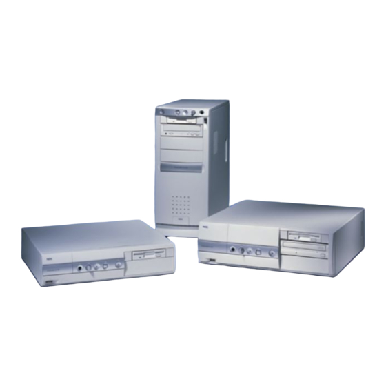
Appendix A, Setting Up a Healthy Work Environment. This guide describes the PowerMate ES 5250 Series of small desktop, desktop, and minitower computers. This chapter highlights system hardware and software, and describes system security. - Page 15 Front features — desktop models A – Device Bay Cover F – Disk Activity Lamp B – Diskette Drive G – Sleep Button/Lamp C – USB Port H – Power Button/Lamp D – Headphone Connector I – 5 1/4-Inch Devices E –...
-
Page 16: System Controls And Lamps
Front features — minitower models A – Power Button/Lamp F – USB Port B – Sleep Button/Lamp G – 5 1/4-Inch Accessible Bays C – Disk Lamp H – Chassis Foot D – Volume Control I – Diskette Drive E – Headphone Connector System Controls and Lamps System controls let you select specific system operations. - Page 17 Power lamp The round lamp in the power button is lit when system power is on. ! CAUTION Do not power off the system while the system is in sleep mode. Sleep button Press this button to suspend system operation when you plan to be away from your computer for a short time.
-
Page 18: Diskette Drive A
Diskette Drive A Use diskette drive A to copy data files to and from a diskette. You can also use it as a bootable drive for loading and starting programs from a diskette. ! CAUTION To prevent damage to your diskette drive and data, do not turn off the system or remove a diskette while the diskette drive busy lamp is lit. -
Page 19: Cd-Rom Drive
Note: The headphone jack and volume control on the front panel support the use of the internal onboard sound device. Installation of an optional sound card in the system disables the front panel headphone jack and volume control. If you install an optional sound card, connect the headphones directly to the sound card (see the instructions that come with the sound card). -
Page 20: Pc Card Adapter
PC Card Adapter If your system has a PC card adapter, you can add PC cards to the system. Inserting a PC card into a PC card slot is similar to inserting a diskette into a diskette drive. Each type of PC card has a different function. - Page 21 Rear features — small desktop models A – PCI Slot H – Keyboard Port B – PCI/ISA Shared Slot I – Mouse Port C – USB Port J – Serial Port 2 D – Power Supply K – Serial Port 1 E –...
-
Page 22: External Connectors
Rear features — minitower models A – Power Supply G – Serial Port 1 B – Line Out Jack H – VGA Monitor Connector C – Microphone In Jack I – USB Port D – LAN Connector J – Printer Port E –... - Page 23 Kingdom and Germany) with a 6-pin mini DIN connector. VGA monitor connector The system supports the Accelerated Graphics Port (AGP) standard, and comes with an external video graphics array (VGA) connector. The connector supports an NEC ™ ® VistaScan monitor, NEC MultiSync monitor, or other VGA-compatible monitor with a 15-pin connector.
-
Page 24: Power Supply Features
Audio connectors The following connectors come integrated on the system board: Microphone in jack The microphone in jack lets you connect a microphone for recording audio information in your data system files. Line out jack The line out jack allows you to connect an amplified output device, such as powered speakers, a stereo tape recorder, or an external amplifier for audio output. - Page 25 Voltage selector switch This switch sets the system voltage to 115 or 230 volts. ! CAUTION Set the switch correctly for the voltage in your area. Most wall outlets in the United States and Canada are 115 volts. Outlets in Europe, Australia, and Asia (except Taiwan) are 230 volts.
-
Page 26: Inside Features
Inside Features See the following figures for the location of features within the system. Feature descriptions follow. Inside the system — small desktop models A – Expansion Slots D – System Board B – Riser Board E – Internal Hard Drive C –... - Page 27 Inside the system — desktop models A – Expansion Slots E – Accessible Device Bays B – Riser Board F – Internal Hard Drive C – Internal Hard Drive G – System Board D – Power Supply Inside the system — minitower models A –...
-
Page 28: System Board
System Board System memory, the processor, and the system battery reside on the system board. The system board also comes with an audio subsystem and a LAN controller, and it supports the AGP standard. See “Front Audio and USB Access” and “External Connectors”... -
Page 29: Chassis
Desktop models two PCI connectors one shared PCI/ISA connector one ISA connector Minitower models three PCI connectors two ISA connectors. Note: Some minitowers have a fourth PCI connector next to the ISA connector. This connector is not supported and cannot be used. Chassis Each model has a state of the art chassis design. -
Page 30: Stand
Desktop models Five bays accommodate an internal 3 1/2-inch hard drive, a 3 1/2-inch diskette drive, a 3 1/2-inch device (for a diskette drive or a hard drive), and two 5 1/4-inch accessible devices. Minitower models Six bays accommodate two internal 3 1/2-inch hard drives, a 3 1/2-inch diskette drive, and three 5 1/4-inch accessible devices. -
Page 31: Speakers
Your computer hardware and software deliver the performance and technologies you need for all your challenging tasks today and into the future. Hardware PowerMate ES 5250 Series systems include the following hardware features: Latest in Processor Technology ® The system comes with an Intel Pentium II, Celeron™,... -
Page 32: Software
Motion Picture Experts Group (MPEG) software. Power Management Options Power management options conserve energy and reduce power costs. Software NEC CSD provides a variety of applications and hardware utilities with your system to let you take advantage of your hardware capabilities. 1-20 Reviewing System Features... -
Page 33: Preloaded Operating System
In the event of operating system problems, you can restore your operating system using the NEC OS Restore CD. The NEC OS Restore program on the CD provides a “Fix OS” Restore option for reinstalling the Windows 95 or Windows 98 operating system while leaving data files intact. - Page 34 NEC WebTelligent using an Internet browser of your choice. ™ NEC WebTelligent Auto Discovery Agent Install NEC WebTelligent Auto Discovery Agent on client systems so they can be managed with the NEC WebTelligent software. 1-22 Reviewing System Features...
- Page 35 Use NEC CCN to detect and announce changes in the processor, main memory, or hard drive when the operating system starts. NEC Auto Backup Utility Use NEC Auto Backup to back up the hard drive when hard drive failure is imminent. ® ®...
-
Page 36: Security
Healthy Environment This is an online version of the printed brochure, Setting up a Healthy Environment. Security The system has hardware, software, and mechanical security features that offer protection against unauthorized access to your system and data. The following security features are available with the system: Password security The CMOS Setup Utility includes a feature that lets you... -
Page 37: Setting Up The System
Setting Up the System Cable Connections Startup Shutdown Power-Saving Operation System Care More Information... -
Page 38: Cable Connections
This chapter provides the information you need to set up and use the PowerMate ES 5250 small desktop, desktop, and minitower computers. Some of the information provided includes cable connections, system startup procedures, system shutdown procedures, and system care. The chapter also provides a matrix showing where to find additional information about your system. -
Page 39: Startup
(if the system board is jumpered for Immediate Boot-Up). When the system starts up, the power lamp lights green to indicate that the system is on. The NEC startup screen appears. Setting Up the System 2-3... - Page 40 At the bottom of this screen, a message like the following appears: Press [ESC] to show POST, [F2] to enter SETUP. Note: When your system is started, it performs a Power-On Self-Test (POST) to check your hardware for any changes since the last startup.
-
Page 41: Shutdown
Shutdown Follow these steps to shut down (power off) your computer. 1. Save your work. See the documentation that comes with your application. 2. Exit the application program. 3. Make sure that the hard drive, diskette drive, and any other drives are not in use. A lit device lamp indicates that the device is in use. -
Page 42: Power-Saving Operation
Power-Saving Operation If the system is running the Windows 95 or Windows 98 operating system, you can put it in Sleep mode — a power- saving state — by pressing the sleep button on the front of your unit. This is a convenient way of conserving energy when you are going to be away from your system for a short period of time. -
Page 43: System Care
Protecting Your System From Damage There are several ways that you can protect your system from possible damage. NEC CSD strongly recommends the following protective measures: Keep the feet on the minitower system turned out. The feet prevent the system from being tipped over. - Page 44 (see “BIOS Features Setup” in Chapter 3). Use appropriate virus detection software regularly to protect your system from computer viruses. If you plan to use software programs other than NEC CSD supplied software, NEC CSD strongly recommends that you take the necessary steps, such as virus checks, to protect your system.
-
Page 45: Keeping Your System In Good Condition
Keeping Your System in Good Condition Maintain the condition of your system by periodically using the following general procedures. WARNING For safety, power off and unplug your system, monitor, and any external devices before cleaning them. Clean the outside of the computer with a soft clean cloth. You can remove stubborn stains with a cloth slightly dampened with a mild detergent. -
Page 46: Moving Or Shipping Your System
Moving or Shipping Your System Use these steps to prepare your system for moving or shipping: 1. Back up the files on the hard drive to diskettes, Zip disks, or tape cartridges. Be sure to take precautions for storing and transporting Zip disks, diskettes, or tape cartridges so that they are not exposed to magnetic fields or electrical impulses. -
Page 47: More Information
More Information Once you have your system up and running, we suggest that you do the following: Install applications provided by NEC CSD from the NEC Application and Driver CD. See “Setting Up a Healthy Work Environment” in Appendix A. -
Page 48: Configuring The System
Configuring the System Configuration Tools and Utilities CMOS Setup Utility Flash Utility NEC OS Restore CD NEC Application and Driver CD NEC Help Center Resolutions for NEC VistaScan USB Monitors Jumper Settings... -
Page 49: Configuration Tools And Utilities
Utility for configuring hardware and the system. It also provides information about the Flash utility for BIOS updates, the NEC OS Restore CD for rebuilding the hard drive and/or restoring the operating system, and the NEC Application and Driver CD for installing the NEC-supplied applications and optional drivers. - Page 50 Peripherals menu, Special Features Setup menu) DMI event log, setting, configuring, viewing CMOS Setup (BIOS Features Setup menu) Drivers for NEC CSD hardware, installing NEC Application and Driver Hard drive, configuring as master or slave, CMOS Setup (Integrated primary or secondary...
- Page 51 Legacy ISA resource control CMOS Setup (PNP/PCI Configuration Setup menu) Memory, checking CMOS Setup (Standard CMOS Setup menu) NEC Help Center online documentation, NEC Application and Driver installing CD (see “Installing the NEC Help Center”) NEC Help Center online documentation, see “Uninstalling the NEC Help...
- Page 52 CMOS Setup (Special Features Setup menu) Serial ports, enabling CMOS Setup (Integrated Peripherals menu) Software provided through NEC, installing NEC Application and Driver Time and date, setting CMOS Setup (Standard CMOS Setup menu) Wake-On LAN (boot the system from a...
-
Page 53: Cmos Setup Utility
Virus protection, enabling CMOS Setup (BIOS Features Setup menu) Windows 95, Windows 98, or Windows NT, NEC OS Restore CD restoring CMOS Setup Utility The CMOS Setup Utility is a program for configuring the BIOS settings for the main components of your computer. -
Page 54: How To Start Cmos Setup
NEC CSD recommends that you print out or write down your current CMOS Setup parameters and store the information in a safe place. This lets you restore your system to the current parameters if you ever need to replace the battery. -
Page 55: How To Use Cmos Setup
How to Use CMOS Setup Use the keys described in the narrow legend near the bottom of the Setup menu to make your selections or exit the current menu. The following table describes the navigation keys. Navigation Keys Function Quits the menu. Enter Executes Command or brings up a submenu. -
Page 56: Standard Cmos Setup
The following menu items are available from the Main menu. Standard CMOS Setup BIOS Features Setup Chipset Features Setup Power Management Setup PNP/PCI Configuration Setup Load Setup Defaults Special Features Setup Integrated Peripherals Supervisor Password User Password Save & Exit Setup Exit Without Saving Press Enter... -
Page 57: Bios Features Setup
Date Time Hard disk type, size, cylinders, heads, preconfiguration mode Diskette Drive Base Memory Extended Memory Other Memory Total Memory BIOS Features Setup Choose the BIOS Features Setup menu by selecting it from the Main menu and pressing Enter ! CAUTION Setting items on this menu to incorrect values can cause your system to malfunction. -
Page 58: Chipset Features Setup
Boot Up Num Lock Status Gate A20 Option Security Option PCI/VGA Palette Snoop OS Select for DRAM > 64MB Delay For HDD (Secs) DMI Event Log Clear All DMI Event Log View DMI Event Log Mark DMI Events as Read Event Log Capacity Event Log Validity Chipset Features Setup... -
Page 59: Power Management Setup
Power Management Setup Choose the Power Management Setup menu by selecting it from the Main menu and pressing Enter ! CAUTION Setting items on this menu to incorrect values can cause your system to malfunction. The following features are available from the Power Management Setup menu. -
Page 60: Pnp/Pci Configuration Setup
Resume by Ring Resume by Alarm Date (of Month) Alarm (appears only when Resume by Alarm is enabled) Time (hh:mm:ss) Alarm (appears only when Resume by Alarm is enabled) Wake Up On LAN Restore AC/Power Loss IRQ[3-7,9-15],NMI Primary IDE 0 Primary IDE1 Secondary IDE 0 Secondary IDE 1... -
Page 61: Load Setup Defaults
PNP OS Installed Resources Controlled By (for IRQs 3, 4, 5, 7, 9, 10, 11, 12, 14, and 15, with settings for PCI/ISA PnP or Legacy ISA) Reset Configuration Data Assign IRQ For VGA Assign IRQ For USB Load Setup Defaults Choose the Load Setup Defaults menu by selecting it from the Main menu and pressing Enter... - Page 62 The following features are available from the Special Features Setup menu. under POST SHOWING Chassis Fan Detected Power Fan Detected CPU Fan Detected Chassis Intrusion Detect Voltage Detected under CPU PLUG & PLAY, CPU Speed listing Disable, Manual, and CPU speed settings under System Monitor Chassis Fan RPM Power Fan RPM...
-
Page 63: Integrated Peripherals
Integrated Peripherals Choose the Integrated Peripherals menu by selecting it from the Main menu and pressing Enter ! CAUTION Setting items on this menu to incorrect values can cause your system to malfunction. The following features are available from the Integrated Peripherals menu. -
Page 64: Supervisor Password
Onboard Sound Onboard LAN Onboard FDC Controller Onboard Serial Port 1 Onboard Serial Port 2 Onboard Parallel Port Parallel Port Mode Supervisor Password Choose the Supervisor Password menu by selecting it from the Main menu and pressing Enter ! CAUTION Setting items on this menu to incorrect values can cause your system to malfunction. -
Page 65: Save & Exit Setup
Follow the prompts in the dialog box to set up, change, or disable the User password. Save & Exit Setup Choose the Save & Exit Setup menu by selecting it from the Main menu and pressing Enter ! CAUTION Setting items on this menu to incorrect values can cause your system to malfunction. -
Page 66: Flash Utility
(ROM) chip in your system. Update the Flash ROM with a BIOS flash diskette. The diskette contains the latest version of the BIOS code. You can get the diskette from NEC CSD or download the BIOS from the NEC CSD website or Bulletin Board System (BBS). -
Page 67: Nec Os Restore Cd
See Chapter 7 for information about using the website or the bulletin board. NEC OS Restore CD The following procedures describe how to use the NEC OS Restore CD that ships with your system. Please read the following sections in their entirety before... -
Page 68: Choosing A Restore Program
Windows OS and factory- shipped drivers (see “Custom Rebuild and Restore”) Fix OS , which provides a Restore option on the NEC OS Restore CD for Windows 95 and Windows 98 systems. The Fix OS restore option reinstalls the Windows operating system while leaving data files intact. -
Page 69: Launching The Nec Os Restore Cd
If possible, back up your data before performing an OS restore. Use the following procedure to launch the NEC OS Restore 1. Power on or restart the system and immediately insert the NEC OS Restore CD into the CD-ROM drive. The Operating System Restore Welcome screen appears. -
Page 70: Auto Rebuild And Restore
This OS Restore program deletes all the data on your hard drive. If possible, back up your data before performing an OS restore. 1. Launch the NEC OS Restore CD and follow the prompts to get to the Restore Mode screen (see “Launching the OS Restore CD”). - Page 71 3. The Partition Information screen that appears in Windows 95 or Windows 98 has three options (Back, FAT 16, and FAT 32) and lets you select the File Allocation Table (FAT) type you want to use for the operating system restore: Click to return to the Operating Mode screen.
-
Page 72: Custom Rebuild And Restore
This OS Restore program deletes all the data on your hard drive. If possible, back up your data before performing an OS restore. 1. Launch the NEC OS Restore CD and follow the prompts to get to the Restore Mode screen (see “Launching the OS Restore CD”). - Page 73 If the table is functional, a Partitioning the Hard Drive screen appears with options allowing you to retain the present partition structure or partition the hard disk using FAT16 or FAT32. If the existing partition table is not functional, the system performs an “Auto”...
- Page 74 5. To partition the hard drive, click on the Continue Partitioning the Hard Drive screen. The Partition Information screen appears (in Windows 95 and Windows 98 systems; in Windows NT 4.0 systems, the FAT16 Partition warning appears as described in step 7 6.
-
Page 75: Fixing The Operating System
Use the following procedure to restore the operating system (Windows 95 and Windows 98 only) to a state for retrieving and backing up data without repartitioning or reformatting the hard drive. Once all data is backed up, perform another NEC OS Restore using the mode. - Page 76 2. Click to do a basic operating system restore. The Fix OS Fix OS screen appears and displays two options (Back and Continue). 3. Click Continue . The Installing Applications screen appears, showing the status of the restore. It also displays the version of Windows OS being installed.
-
Page 77: Nec Application And Driver Cd
(see “Launching the OS Restore CD”). NEC Application and Driver CD Your system comes with an NEC Application and Driver CD. Use this CD to install any or all of the software that comes with your system, including applications... - Page 78 Doing so can damage the operating system. Launch the NEC Application and Driver CD as follows: In systems running the Windows NT operating system, insert the NEC Application and Driver CD after the system reboots and you have chosen the Windows NT Workstation operating system.
-
Page 79: Installing Software
Selection Tabs — Located just below the title bar, each tab represents a software category. The selection tabs include applications, drivers, utilities, Internet browsers, and the online NEC Help Center. Description — Located in the bottom portion of the dialog box, the text describes the selected or highlighted software category or application, driver, and so on. -
Page 80: Nec Help Center
NEC Help Center NEC CSD provides an online NEC Help Center. The Help Center comes on the NEC Application and Driver CD. It is easy to install and it provides an overview to your computer. To install the NEC Help Center, see the following section, “Installing the NEC Help Center.”... -
Page 81: Uninstalling The Nec Help Center
Follow the instructions in the previous section, “NEC Application and Driver CD” to install the NEC Help Center online documentation. The NEC Help Center is in the list of applications that appear when the NEC Application and Driver CD is launched. Install it in the same manner as the applications and drivers in the list. -
Page 82: Resolutions For Nec Vistascan Usb Monitors
Resolutions for NEC VistaScan USB Monitors The following table lists the supported resolutions for NEC PowerMate Series systems with 15-inch and 17-inch NEC ™ VistaScan USB monitors. ! CAUTION Setting resolutions other than the rates listed in the following table generates a “black" monitor screen. -
Page 83: Jumper Settings
Jumper Settings Some devices in the system have pins that must be jumpered according to way the device is used in your computer, or the way your system is configured. For example, a hard drive or CD-ROM drive must be jumpered as a master or slave device to correspond to the way it is cabled. -
Page 84: Setting Onboard Video
Locating system board jumpers A – JVGA1 (VGA Mode) C – JP1 (Power On Mode) B – JBAT1 (CMOS Clear) Setting Onboard Video If you add a graphics board to your system, you must disable the onboard video by changing the jumper setting on block JVGA1 (see the following table). -
Page 85: Clearing Cmos
Clearing CMOS If you need to manually reset your CMOS settings to their factory state, change the jumper setting on block JBAT1 after the system has been unplugged. The following table lists the jumper settings and the function of each setting. Move the jumper back to pins 1-2 (to keep future CMOS changes) after waiting approximately five seconds. -
Page 86: Changing A System Board Jumper Setting
Change a system board jumper setting using these guidelines. See the previous sections for specific jumper settings. Note: NEC CSD recommends using needle- nose pliers to move a jumper. 1. Record your customized CMOS settings before changing the jumpers that affect the CMOS Setup Utility. See “The CMOS Setup Utility”... -
Page 87: Nec 32X Cd-Rom Drive Jumpers
For a minitower system, see “Replacing the Minitower Side Covers.” NEC 32X CD-ROM Drive Jumpers The NEC 32X CD-ROM drive CDR-1900A/PBM uses a three-position jumper block to configure the master/slave and cable select options. The user-selectable jumper settings are as follows. -
Page 88: Zip Drive Jumpers
Zip Drive Jumpers The three-position jumper block for the Zip drive is located on the rear of the drive. The following description applies when the rear of the drive is viewed with the IDE connector to the left of the jumper block, and the power connector to the right. -
Page 89: Managing System Resources
Managing System Resources System Management Tools LANDesk Client Manager Cheyenne Backup NEC ToolTelligent Suite NEC WebTelligent NEC SNMP Agent NEC Configuration Change Notification NEC Auto Backup Utility... -
Page 90: System Management Tools
NEC WebTelligent software for server-side management, NEC WebTelligent Auto Discovery Agent to install on client systems, the NEC SNMP Agent, the NEC Auto Backup Utility, and the NEC Configuration Change Notification. See the following table for a quick guide to the utilities, tools, or procedures required in managing system resources. - Page 91 Management Activity Method, Tool, or Utility Hard drive backups, performing on schedule Cheyenne Backup utility Hard drive failure, detecting Cheyenne Backup NEC Auto Backup utility Hard drive, monitoring NEC Configuration Change Notification (CCN) Hardware monitoring (for chassis intrusion) LANDesk Client Manager...
-
Page 92: Landesk Client Manager
PC and can be used by system administrators to manage groups of computer systems. Install LANDesk Client Manager from the NEC Application and Driver CD. For installation information, see “Launching the Application and Driver CD” in Chapter 3. - Page 93 With Client Manager, you can perform the following tasks: using the Wake-On LAN feature, get remote systems on the network up and running from a powered-off state (for example, to perform off-hour maintenance) review system inventory of workstation hardware and software components view DMI-compliant component information set security features to change password (local machine)
-
Page 94: Pc Health Indicator
PC Health Indicator PC health indicator consists of three parts: managing workstations selecting the PC Health meter monitoring PC Health. Managing Workstations Client Manager sets up a connection to all the workstations running on the network to allow the administrator to monitor the functions of each workstation. -
Page 95: Monitoring Pc Health
Monitoring PC Health PC health can be determined by monitoring various system components for threshold levels. Some of the components that are monitored include: drive space prediction of hard drive failure (Smart Hard Drive failure prediction) free virtual memory temperatures power supplies chassis opened GDI used... -
Page 96: Dmi
audio keyboard/mouse video system resources I/O ports operating system network applications system files user information. You can also view the current system configuration, edit user information, and create or restore file snapshots. As a part of the LANDesk Client Manager, the Desktop Management Interface (DMI) is the standard interface used to manage system components on the computer. -
Page 97: Monitoring Capabilities
Monitoring Capabilities Your PowerMate computer has a chip mounted on the system board that supports many new and advanced real-time monitoring capabilities used by DMI. This chip provides the following features: an integrated temperature sensor with configurable interrupt generation based on upper and lower temperature limits a power supply monitor with configurable interrupt generation based on upper and lower voltage limits... -
Page 98: Using The Chassis Intrusion Notification Feature
Using the Chassis Intrusion Notification Feature LANDesk Client Manager allows you to monitor your system against chassis intrusion. Whenever the chassis is opened, LANDesk Client Manager logs the intrusion and reports the incident in a screen message the next time the system is booted. -
Page 99: Ldcm Admin Function
The LANDesk Client Manager (LDCM) Admin function is installed on the C drive of your computer when LANDesk Client Manager is installed from the NEC Application and Driver CD. For information on installing LANDesk Client Manager, see “Launching the Application and Driver CD” in Chapter 3. -
Page 100: Nec Tooltelligent Suite
™ NEC WebTelligent management software for server systems NEC WebTelligent Auto Discovery Agent for client systems in a network managed with NEC WebTelligent software NEC Desktop SNMP Agent for monitoring the features, configurations, and locations of computers in your network... -
Page 101: Installing Tooltelligent Utilities
NEC Auto Backup Utility, to detect predicted hard drive failures and to automatically back up the data from the failing drive Use the ToolTelligent interface to activate one or more of the utilities in the ToolTelligent suite. Installing ToolTelligent Utilities NEC ToolTelligent Utilities are installed using the NEC Application and Driver CD. -
Page 102: Nec Webtelligent
Interface (DMI) version 2.0, and the world wide web to perform administrative tasks across multiple platforms, either locally or remotely over a network. Through NEC WebTelligent, the managed client desktop PC administrator can manage from a desktop computer using the Netscape or Microsoft Internet Explorer web browser. -
Page 103: Nec Webtelligent Features
NEC WebTelligent NEC WebTelligent Features NEC WebTelligent provides the administrator with the following features and benefits. WebTelligent Account Management Create and delete user accounts Change user passwords Disable user accounts Asset Management Discovery of networked DMI desktops Display system and hardware component attributes... -
Page 104: Nec Webtelligent Requirements
View system and log events Security Intranet user authentication Chassis intrusion monitoring Reduced Costs WebTelligent is free with the purchase of an NEC PowerMate Managed desktop computer WebTelligent is available as a free download from the NEC CSD website ( www.nec-computers.com... - Page 105 Microsoft Windows 95 or Windows 98 Operating System or Windows NT 4.0 Operating System and associated web server software Microsoft Windows 95 or Windows 98 with Microsoft Personal Web Server version 1.0 or later Microsoft Windows NT with Peer Web Server version 2.0 or later Microsoft Windows NT with Microsoft Internet Information Server version 3.0 or later...
-
Page 106: Nec Webtelligent Installation
NEC Auto-Discovery Agent TCP/IP. NEC WebTelligent Installation Install the WebTelligent software and the NEC Auto Discovery Agent software on a Windows 95, Windows 98, or Windows NT web server as follows. 1. Close all open applications before installing WebTelligent and Auto Discovery Agent. - Page 107 Scroll to the bottom of the page and set the default document to login.html Click 5. Install the NEC Auto Discovery Agent software on a managed client. If you are installing the Auto Discovery Agent from the NEC Application and Driver CD, see “Installing ToolTelligent Utilities.”...
- Page 108 Look for the directory C:\Program files\PBNEC\WebTelligent Discovery . If it is not there, install the software Agent from the NEC Application and Driver CD or download it from the NEC CSD website www.nec-computers.com 6. Open WebTelligent as follows.
- Page 109 WebTelligent Login screen Click Login . The WebTelligent screen displays (see the following screen). Click on the WebTelligent screen to collect Discover a list of machines to manage. Click on the desktop to be managed. A Workstation screen opens to display a summary of the workstation attributes.
-
Page 110: Nec Snmp Agent
NEC SNMP Agent The NEC Desktop Simple Network Management Protocol (SNMP) Agent is an extension to the Microsoft SNMP Agent. The NEC SNMP Agent permits a network administrator to manage NEC PowerMate clients. The NEC SNMP Agent performs the following major functions: Assets Management —... -
Page 111: Installing The Nec Snmp Agent
NEC SNMP Agent on Microsoft Windows 95, Windows 98, or Microsoft Windows NT configured systems. Installing the NEC SNMP Agent Install the NEC SNMP Agent on your Windows 95, Windows 98, or Windows NT configured system as follows. CAUTION Do not install both the NEC SNMP Agent and LANDesk Client Manager on the same computer. -
Page 112: Configuring The Nec Snmp Agent For Windows 95 Or Windows 98
1. If you are installing the NEC SNMP Agent from the NEC Application and Driver CD, see “Installing ToolTelligent Utilities” for installation instructions. 2. If you are downloading the software from the NEC CSD website ( www.nec-computers.com ), save the download file in your C:\Temp directory or other appropriate directory. - Page 113 157.123.176.100) must be entered in the Traps for “Public Community” to receive traps from the NEC SNMP agents. For the NEC SNMP Agent to send a trap to the NEC SNMP Desktop Manager, the port number can be configured from the registry: "HKEY_LOCAL_MACHINE\SOFTWARE\...
-
Page 114: Configuring The Nec Snmp Agent For Windows Nt
Configuring the NEC SNMP Agent for Windows NT Configure the NEC SNMP Agent for Windows NT as follows. 1. In the Windows taskbar, click , point to Start Settings and click Control Panel 2. At the Control Panel, double click the Network icon. -
Page 115: Nec Configuration Change Notification
157.123.176.100) must be entered in the Traps for “Public Community” to receive traps from the NEC SNMP agents. For the NEC SNMP Agent to send a trap to the NEC SNMP Desktop Manager, the port number can be configured from the registry: "HKEY_LOCAL_MACHINE\SOFTWARE\... -
Page 116: Nec Auto Backup Utility
Windows Start menu. The utility has some configuration options that are accessible through the system tray icon. The NEC Tools group on the Start menu includes a ReadMe file containing recent information about the utility as well as access to a Help document. -
Page 117: Installing Options
Installing Options General Rules Safety Precautions Small Desktop and Desktop System Unit Cover Minitower System Unit Covers System Board Options Expansion Boards Data Storage Devices... -
Page 118: General Rules
This chapter provides installation instructions for a variety of industry-standard and NEC CSD expansion options that you can add to your system. Included in the chapter are instructions for memory module upgrade processor upgrade expansion board installation data storage device installation. -
Page 119: Safety Precautions
Safety Precautions Observe safety rules when working inside the system and when handling computer components. Avoid electric shock or personal injury by observing the following warning. WARNING Before removing system covers, turn off the power and unplug the system power cable. Power is removed only when the power cable is unplugged. -
Page 120: Small Desktop And Desktop System Unit Cover
Always hold a chip or board by its edges. Avoid touching the components on the chip or board. Take care when connecting or disconnecting cables. A damaged cable can cause a short in the electrical circuit. When installing a cable, route the cable so it is not pinched by other components and is out of the path of the system unit covers. - Page 121 Note: If the cover is removed, LANDesk Client Manager logs the intrusion and reports it in a screen message the next time the system is booted. This message appears every time the system is rebooted until the report is cleared. For more information on closing the notification window and clearing the message, see “Using the Chassis Intrusion Notification Feature”...
- Page 122 Locating the cover screw — small desktop A – Cover Screw Locating the cover screws — desktop A – Cover Screws 5. From the rear of the system, grasp the sides and slide the cover about an inch away from the front. Note: The cover fits tightly.
- Page 123 Releasing the small desktop cover A – Slots C – Tabs B – Tabs D – Metal Securing Rail Installing Options 5-7...
-
Page 124: Replacing The Small Desktop Or Desktop Cover
Releasing the desktop cover A – Slots C – Slots B – Tabs D – Tabs Replacing the Small Desktop or Desktop Cover Replace the small desktop or desktop cover as follows. ! CAUTION To prevent damage to system cables, carefully tuck the cables out of the path of the cover. - Page 125 3. Slide the cover forward to meet the front panel (see the following figure). Note: The cover fits tightly. If the cover does not slide off all the way to the front panel, place one hand on the front of the unit while you slide the cover forward from the rear.
- Page 126 Replacing the desktop cover A – Slots C – Slots B – Tabs D – Tabs 4. Secure the cover with the cover screw(s). (See the previous section, “Removing the Small Desktop or Desktop Cover.”) 5. Replace any lock or security cable (if one has been installed).
-
Page 127: Minitower System Unit Covers
Minitower System Unit Covers The following sections describe how to remove and replace the minitower system unit covers and open the chassis floor. (For small desktop and desktop systems, see “Small Desktop and Desktop System Unit Cover.”) Removing the Minitower Side Covers Before installing optional hardware inside your system, you must first remove one or both of the side covers on the system unit. - Page 128 1. Turn off and unplug the system unit. 2. Disconnect any external options (such as a keyboard and monitor) from the front or rear of the system unit. ! CAUTION Electrostatic discharge can damage computer components. Discharge static electricity by touching a metal object before removing the system unit side cover.
- Page 129 Locating the top and left side cover screws — minitower A – Top Cover Screw B – Left Side Cover Screw Locating the right side cover screw — minitower A – Chassis Bracket C – Screwdriver Hole B – Right Side Cover Tab D –...
- Page 130 5. Push up on the slide lock at the rear of the chassis to unlock the left side cover (see the following figure). 6. While holding the rear of the system unit with one hand, grasp the recess in the left side cover with your other hand and slide the cover back about an inch.
-
Page 131: Replacing The Minitower Side Covers
Replacing the Minitower Side Covers Replace the side covers as follows. ! CAUTION Ensure that all cables are positioned to prevent kinking, crimping, abrasion, or cutting while installing the side cover. Check that the ribbon cables are folded along their fold lines and out of the direct path of the side cover. - Page 132 Replacing the minitower left side cover A – Cover Tabs (under cover) C – Side Cover Flanges B – Tab Slots D – Securing Rails 4. Press the top and bottom of the side cover against the chassis and slide the cover toward the front of the chassis until it locks in place.
-
Page 133: Removing The Minitower Top Cover
6. Replace the cover screws. For the left side cover, replace the screw that secures the back edge of the cover to the edge. For the right side cover, replace the screw that secures the right side cover tab to the chassis bracket within the system (see the figure in “Removing the Minitower Side Covers”). -
Page 134: Replacing The Minitower Top Cover
2. Remove the front panel (see “Removing the Front Panel — Minitower,” later in this chapter). 3. Remove the screw holding the top cover to the rear of the chassis (see the figure in “Removing the Minitower Side Covers”). 4. Lift the back end of the cover up about an inch to free its restraining tabs. -
Page 135: Opening The Chassis Floor
2. Align the tabs under the front edge of the cover with the slots in the top edge of the chassis. 3. Pull the cover towards the rear of the chassis and set it down over the chassis. 4. Check that the corners on the rear of the cover fit over the back of the chassis. -
Page 136: Closing The Chassis Floor
6. Grasp the two board handles and pull the board out further if you cannot access to the components you are upgrading. If you need to replace the board, see “Removing the System Board — Minitower” later in this chapter. Opening the chassis floor —... -
Page 137: System Board Options
3. Secure the floor to the chassis with the previously removed screw. 4. Place the system unit upright and swivel the two chassis feet out, perpendicular to the system unit. 5. Replace the left side cover (see “Replacing the Minitower Side Covers”). -
Page 138: Memory Upgrade
Memory Upgrade Memory upgrades are installed into memory module sockets on the system board. Your system uses dual inline memory modules (DIMMs). The system board has two module sockets and supports up to 512 MB of non-ECC high-speed memory. The system supports 168-pin SDRAM modules in 32-, 64-, 128-, and 256-MB unbuffered PC100 memory configurations. -
Page 139: Checking System Memory
Supported DIMMs DIMM Size Non-ECC Configuration 32 MB 4 Mbit x 64 64 MB 8 Mbit x 64 128 MB 16 Mbit x 64 256 MB 32 Mbit x 64 Sample DIMM Upgrade Paths* Total Memory DIMM 1 DIMM 2 32 MB 32 MB 64 MB... -
Page 140: Removing A Dimm
2. With the left mouse button, click . The Properties tab shows the random access memory (RAM). General This is the amount of system memory in your computer. In Windows 95 or Windows 98, you can also find the amount of memory by pointing to , clicking the right My Computer... - Page 141 3. Press the plastic clips at the outer edges of the socket away from the memory module (see the following figure). This ejects the DIMM from the socket. Removing a DIMM A – Plastic Clip 4. If installing a DIMM, see the next section, “Installing a DIMM.”...
-
Page 142: Installing A Dimm
Installing a DIMM Install a memory module by performing the following steps. 1. Remove the system board to access DIMM sockets. In a small desktop system, see “Removing the System Board — Small Desktop.” In a desktop system, see “Removing the System Board —... - Page 143 In a minitower system, see “Replacing the System Board — Minitower.” Inserting a DIMM A – Plastic Clips B – Notches 7. Replace the cover(s): For a small desktop or desktop system, see “Replacing the Small Desktop or Desktop Cover.” For a minitower system, see “Replacing the Minitower Side Covers.”...
-
Page 144: Processor Upgrade
! CAUTION NEC recommends that you contact your NEC dealer or NEC service center for assistance in upgrading your processor. Incorrect installation of the processor cartridge and heat sink can damage the processor, system board, or both. -
Page 145: Removing The Celeron Or Pentium Iii Processor Cartridge
Remove the Celeron or Pentium III processor cartridge from the system board as follows. Note: NEC CSD recommends that you print out or write down your current CMOS Setup parameters and store the information in a safe place before removing your processor. - Page 146 3. Remove the system board to access processor socket. In a small desktop system, see “Removing the System Board — Small Desktop.” In a desktop system, see “Removing the System Board — Desktop.” In a minitower system, see “Removing the System Board —...
-
Page 147: Installing The Celeron Or Pentium Iii Upgrade Processor Cartridge
Installing the Celeron or Pentium III Upgrade Processor Cartridge Install the upgrade processor cartridge as follows. Note: NEC CSD recommends that you print out or write down your current CMOS Setup parameters and store the information in a safe place before installing a processor. - Page 148 ! CAUTION Before picking up the processor cartridge, reduce static discharge by touching the metal chassis of the system unit. 2. Align the cartridge with the guides in the retention mechanism (see the following figure). The cooling fan faces the rear of the chassis. 3.
- Page 149 5. Connect the cooling fan cable to its connector on the system board. 6. Replace the system board. In a small desktop system, see “Replacing the System Board — Small Desktop.” In a desktop system, see “Replacing the System Board —...
-
Page 150: Removing The Pentium Ii Processor Cartridge
Remove the Pentium II processor cartridge installed on the system board as follows. Note: NEC CSD recommends that you print out or write down your current CMOS Setup parameters and store the information in a safe place before removing your processor. - Page 151 3. Remove the system board to access processor socket. In a small desktop system, see “Removing the System Board — Small Desktop.” In a desktop system, see “Removing the System Board — Desktop.” In a minitower system, see “Removing the System Board —...
- Page 152 7. While holding the screwdriver in place, carefully pull up on the end of cartridge just enough to release it from the lever. 8. Repeat with the other locking lever and end of the cartridge. ! CAUTION Before picking up the processor cartridge, reduce static discharge by touching the metal frame of the system unit.
-
Page 153: Installing The Pentium Ii Upgrade Processor Cartridge
Installing the Pentium II Upgrade Processor Cartridge Install the Pentium II upgrade processor cartridge by following these steps. Note: NEC CSD recommends that you print out or write down your current CMOS Setup parameters and store the information in a safe place before installing a processor. - Page 154 4. Replace the system board. In a small desktop system, see “Replacing the System Board — Small Desktop.” In a desktop system, see “Replacing the System Board — Desktop.” In a minitower system, see “Replacing the System Board — Minitower.” 5.
-
Page 155: System Board
6. Replace the system unit cover. For a small desktop or desktop system, see “Replacing the Small Desktop or Desktop Cover.” For a minitower system, see “Replacing the Minitower Side Covers.” 7. Press the power button to start the system. Press enter the CMOS Setup Utility. - Page 156 2. Pull the system board latch away from the system unit (see the following figure). This releases the system board and slides it partway out of the system. 3. Carefully slide the board the rest of the way out, taking care not to lift the board before it is free of the chassis.
-
Page 157: Replacing The System Board - Small Desktop
Replacing the System Board — Small Desktop Take care when replacing the system board. Replacing the board requires the use of the chassis latch. Incorrect use of the chassis latch can damage the latch. ! CAUTION Take care in replacing the system board in your computer. - Page 158 Correct alignment of the system board — small desktop A – Rail C – Edge of Chassis B – Latch Open D – Edge of System Board Incorrect alignment of the system board — small desktop 5-42 Installing Options...
- Page 159 A – Latch in Incorrect Position C – Edge of Chassis B – System Board Rail D – Edge of System Board ! CAUTION To prevent damage to the latch, align the system board with the outside edge of the chassis before closing the latch.
- Page 160 If the system board is aligned correctly, you might need to push the outside edges of the board to fully seat it into the connector on the riser board. Check the position of the chassis latch. The system board is secured when the latch is parallel with the outside edge of the board.
-
Page 161: Removing The System Board - Desktop
Removing the System Board — Desktop Use this procedure to remove the system board from a desktop system. 1. Remove the system unit cover (see “Removing the Small Desktop or Desktop Cover”). 2. Remove the screws that secure the left side bracket to the chassis (see the following figure). -
Page 162: Replacing The System Board - Desktop
Preparing to remove the system board — desktop A – System Board C – Side Bracket B – System Board Latches D – Side Bracket Tabs 6. Carefully slide the board the rest of the way out, taking care not to lift the board before it is free of the chassis. 7. - Page 163 Use the following procedure to use the latches correctly. 1. Make sure the chassis latches are in the open position. 2. Position the narrow ends of the system board rails in the chassis guides. 3. Slide the system board partway into the system unit along the chassis rail guides.
-
Page 164: Removing The System Board - Minitower
Check the position of the chassis latches. The system board is secured when the latches are parallel with the outside edge of the board. 5. Hook the tabs of the left side bracket into the slots on the front left edge of the chassis. Fit the back edge of the bracket over the back edge of the chassis. -
Page 165: Replacing The System Board - Minitower
Removing the system board — minitower A – Chassis Floor D – Riser Board B – System Board E – System Board Connector C – Handles Replacing the System Board — Minitower Use the following procedure to replace the system board. 1. - Page 166 4. Use the two handles on the board to carefully slide the system board partway into the chassis, along the rail guides. Replacing the system board — minitower A – System Board C – Rail Guides B – Handles/Rails 5. Stop sliding the board when the edge of the system board aligns with the hinged edge of the chassis floor.
-
Page 167: Expansion Boards
7. Close the chassis floor (see “Closing the Chassis Floor”). 8. Place the system unit upright and swivel the feet out, perpendicular to the system unit. 9. Replace the left side cover (see “Replacing the Minitower Side Covers”). Expansion Boards Your system supports industry standard architecture (ISA) 8- and 16-bit expansion boards (Plug and Play and non-Plug and Play). - Page 168 Expansion board slots and connectors — small desktop A – Slot for PCI or ISA Board C – Shared PCI/ISA Connector B – Slot for PCI Board D – PCI Connector Expansion board slots and connectors — desktop A – Slots for PCI Boards D –...
-
Page 169: Installing And Removing Expansion Boards
Expansion board slots and connectors — minitower A – Slots for ISA Boards D – Not Used B – Slots for PCI Boards E – ISA Connectors C – PCI Connectors Note: If the minitower riser board has four PCI connectors, the fourth PCI connector (the lowest one, next to the ISA connector) is not supported and cannot be used. -
Page 170: Installing An Expansion Board - Small Desktop Or Desktop
Installing an Expansion Board — Small Desktop or Desktop To install an expansion board in a small desktop or desktop system, use the following steps. 1. Remove the system unit cover (see “Removing the Small Desktop or Desktop Cover”). 2. Follow any preinstallation instructions that come with the expansion board (such as setting jumpers on the board). - Page 171 Removing a slot cover — small desktop A – Screw B – Slot Cover 5. Holding the board by its edges or its bracket, insert the board into the expansion slot (see the following figure). Press the board firmly into the expansion board connector on the riser board.
-
Page 172: Removing An Expansion Board - Small Desktop Or Desktop
Installing an expansion board — small desktop Removing an Expansion Board — Small Desktop or Desktop To remove an expansion board from a small desktop or desktop system, use the following steps. 1. Remove the system unit cover (see “Removing the Small Desktop or Desktop Cover”). -
Page 173: Installing An Expansion Board - Minitower
Installing an Expansion Board — Minitower To install an expansion board in a minitower system, use the following steps. 1. Remove the left side cover (see “Removing the Minitower Side Covers”). 2. Swivel the two feet inward, out of the way. 3. - Page 174 Removing a slot cover — minitower A – Screw C – Slot Cover B – Locking Bracket 8. Holding the expansion board by its edges or its bracket, insert the board into the expansion slot (see the following figure). 9. Press the board firmly into the expansion board connector on the riser board.
-
Page 175: Removing An Expansion Board - Minitower
Installing an expansion board — minitower A – Screw B – Expansion Board 12. Attach any signal cables required by the expansion board. 13. If you slid the system board partway out of the chassis, slide it back in (see “Closing the Chassis Floor”). 14. - Page 176 3. Position the system unit on its side, with the open left side facing up. 4. If necessary, slide the system board partway out of the chassis to reach the expansion board (see “Opening the Chassis Floor”). 5. Label and remove any cables connected to the board. 6.
-
Page 177: Data Storage Devices
Data Storage Devices The system board in the computer supports the following storage devices: two diskette drives up to four IDE drives, such as IDE hard drives, an IDE CD-ROM drive, DVD-ROM drive, and an IDE Zip drive Other storage devices might require the installation of a compatible controller board. - Page 178 one 3 1/2-inch internal hard drive bay (1-inch high, thin-height) two 5 1/4-inch accessible device bays (1.6-inch high, half-height) minitower system — six bays one 3 1/2-inch accessible device bay that contains the standard 1.44-MB diskette drive two 3 1/2-inch internal hard drive bays (1-inch high, thin-height) three 5 1/4-inch accessible device bays (1.6-inch high, half-height)
- Page 179 The following figures show the device bay locations in the small desktop, desktop, and minitower models. Locating device bays — small desktop A – 3 1/2-Inch Internal Bay C – 5 1/4-Inch Accessible Bay B – 3 1/2-Inch Accessible Bay Locating device bays —...
-
Page 180: Preparing The Device
Locating device bays — minitower A – 3 1/2-Inch Internal Bays C – 5 1/4-Inch Accessible Bays B – 3 1/2-Inch Accessible Bay Preparing the Device Before installing a storage device in the system, follow any preinstallation instructions that come with the device. For example, check the following information: Diskette drive —... -
Page 181: Connecting Device Cables
Connecting Device Cables The cables used for installing optional storage devices include: diskette drive signal cable IDE signal cables internal SCSI device cables PC card adapter cables system power cables. Riser board cable connectors are shown in the following figures. Riser board cable connectors —... - Page 182 Riser board auxiliary cable connectors — small desktop A – CD Audio In Connector F – NLX Connector (System Board) B – Modem In Connector G – Wake On Remote Connector C – Chassis Intrusion Connector H – Wake-ON LAN Connector D –...
- Page 183 Riser board cable connectors — desktop A – Secondary IDE Connector C – Diskette Drive Connector B – Primary IDE Connector Riser board auxiliary cable connectors — desktop A – Chassis Intrusion Connector D – Front Feature Connector B – Fan Connector E –...
- Page 184 Riser board cable connectors — minitower A – Secondary IDE Connector C – Diskette Drive Connector B – Primary IDE Connector Riser board auxiliary cable connectors — minitower A – Not Used G – CD Audio In Connector B – Chassis Intrusion Connector H –...
- Page 185 Use the following table when configuring IDE drives on the primary and secondary IDE connectors on the riser board. If installing a DVD-ROM device, substitute the DVD-ROM for the CD-ROM in the following table. IDE Connector Configuration Configuration Primary connector Secondary connector 1 device (hard drive) Master - hard drive...
- Page 186 IDE Connector Configuration Configuration Primary connector Secondary connector 4 devices (hard drive, hard Master - hard drive Master - CD-ROM drive, CD-ROM, tape Slave - hard drive Slave - tape backup backup) 4 devices (hard drive, hard Master - hard drive Master - CD-ROM drive, CD-ROM, Zip drive) Slave - hard drive...
-
Page 187: Diskette Drive Signal Cable
Systems with a SCSI adapter board come with a four- connector, 68-pin SCSI device cable. The cable connects an internal SCSI device available from NEC CSD to the 68-pin connector on the SCSI adapter board. Use the four-connector cable to connect up to three internal SCSI devices to the adapter board. -
Page 188: Pc Card Adapter Cable
PC Card Adapter Cable Two PCMCIA-compliant cables come with the PC card adapter available in some systems. The cables are bound together, and connect to the dual PCMCIA ports on the PC adapter board and the connectors on the back of the PC card adapter. - Page 189 Note: The appearance of your device might vary from the one shown. 1. Connect the signal cable connector to the connector on the IDE drive. Take care to prevent bending drive connector pins. Align the cable connector as shown in the following figure. 2.
-
Page 190: Diskette Drive Cabling
4. If you are installing a CD-ROM drive or DVD-ROM drive and your system has speakers, connect the audio cable to the CD Audio In connector on the riser board or an audio board (see the instructions that come with the drive). -
Page 191: Pc Card Adapter Cabling
Connecting an internal SCSI device A – SCSI Cable B – Power Cable 4. See the documentation that comes with your SCSI device for configuration information. PC Card Adapter Cabling The following procedure describes how to cable a PC card adapter. -
Page 192: Network Board Wake-On Lan Cabling
Network Board Wake-On LAN Cabling If your computer has the optional 10/100 MB network board, your system can be readied for “Wake-On LAN” by connecting the Wake-On LAN cable. Wake-On LAN allows your system to be powered up remotely by a server computer. Cable the network board for Wake-On LAN as follows. -
Page 193: Installing Storage Devices
7. Replace the cover(s): For a small desktop or desktop system, see “Replacing the Small Desktop or Desktop Cover.” For a minitower system, see “Replacing the Minitower Side Covers.” 8. Enable Wake-On LAN through CMOS Setup Utility (see Chapter 3 for information). Installing Storage Devices The following subsections describe how to install 3 1/2-inch and 5 1/4-inch drives in the system. - Page 194 2. Locate the three locking tabs inside the front panel (near the upper edge). Squeeze the right two tabs together to release them from the slots in the chassis. Then press the left-most locking tab out of its slot. Note: The three tabs along the top of the front panel are locking tabs that must be released before the panel can be removed (see...
-
Page 195: Replacing The Front Panel - Small Desktop
Replacing the Front Panel — Small Desktop Replace the small desktop front panel as follows. 1. Align the front panel posts with the holes in the front of the system unit (see the following figure). Align the front USB port with the cutout on the front panel. 2. -
Page 196: Removing The Front Panel - Desktop
Removing the Front Panel — Desktop Remove the desktop front panel before installing a device in one of the 5 1/4-inch accessible device bays. If you are installing an accessible 5 1/4-inch device, you might also need to remove the blank panel that covers the bay on the front panel and/or the metallic shield on the chassis. - Page 197 4. Identify the bay on the front panel for the device being installed. 5. Remove the blank plastic panel from the selected bay by pressing the panel tabs from inside the front panel and pushing the blank panel out (see the following figure). 6.
-
Page 198: Replacing The Front Panel - Desktop
Replacing the Front Panel — Desktop If a 5 1/4-inch device has been removed from your system, you need to replace the blank panel before replacing the front panel. The blank panel covers the opening previously used by the device. Replace the desktop front panel as follows. -
Page 199: Removing The Front Panel - Minitower
Aligning the front panel — desktop 5. Replace the system unit cover (see “Replacing the Small Desktop or Desktop Cover”). Removing the Front Panel — Minitower Remove the front panel before installing a device in a 5 1/4- inch accessible device bay. The front panel does not need to be removed if you are installing an internal 3 1/2-inch hard drive. - Page 200 1. Remove the left side cover (see “Removing the Minitower Side Covers”). 2. From inside the chassis, squeeze the two front panel locking tabs in the lower left and right corners (see the following figure). 3. Carefully push the tabs out until they release the bottom of the front panel.
- Page 201 5. Identify the bay on the front panel for the device being installed. 6. Remove the blank plastic panel from the selected bay by pressing the panel tabs from inside the front panel and pushing the blank panel out (see the following figure). Locating the blank panel tabs —...
-
Page 202: Replacing The Front Panel - Minitower
Replacing the Front Panel — Minitower Replace the front panel as follows. Note: Before replacing the front panel, if you removed a 5 1/4-inch device from your system and didn't replace it, you need to cover the opening in the chassis and the front panel. 1. -
Page 203: Installing A 5 1/4-Inch Device - Small Desktop And Desktop
Installing a 5 1/4-Inch Device — Small Desktop and Desktop Use the following procedure to install a 5 1/4-inch device into a 5 1/4-inch accessible device bay. Note: A 3 1/2-inch device can also be installed in a 5 1/4-inch accessible device bay. Place the device in a 5 1/4-inch frame adapter and then follow the instructions in this section. - Page 204 Inserting a 5 1/4-inch device — small desktop 5. Connect the device cables (see “Connecting Device Cables” and “Cabling Storage Devices”). 6. Insert the device the rest of the way into the device bay, making sure that the locking tabs on the sides of the drive engage the brackets on each side of the device bay.
-
Page 205: Installing A 5 1/4-Inch Device - Minitower
8. Replace the front panel. In a small desktop system see “Replacing the Front Panel — Small Desktop.” In a desktop system, see “Replacing the Front Panel — Desktop.” 9. Replace the system unit cover (see “Replacing the Small Desktop or Desktop Cover”). 10. - Page 206 4. From the front of the system, slide the device, connector end first, into the device bay. Slide it in far enough for access to the connectors at the rear of the device. If necessary, remove the top cover for better access to the device connectors (see “Removing the Minitower Top Cover”).
-
Page 207: Installing A 3 1/2-Inch Hard Drive - Small Desktop
You can upgrade the system by replacing the existing hard drive with a higher capacity drive available from NEC CSD. To install a 3 1/2-inch internal hard drive, proceed as follows. 1. Follow the preinstallation instructions that come with your device, such as setting jumpers. - Page 208 4. Align the screws on the new hard drive with the holes in the bracket. 5. Secure the hard drive to the bracket with the four screws that came with the drive or the screws from the old drive (see the following figure). Internal hard drive screws —...
-
Page 209: Installing A 3 1/2-Inch Hard Drive - Desktop
9. Replace the system unit cover (see “Replacing the Small Desktop or Desktop Cover”). 10. Run the Setup program to set the new configuration (see “CMOS Setup Utility” in Chapter 3). Installing a 3 1/2-Inch Hard Drive — Desktop The desktop system has an internal hard drive bay located near the right rear corner of the chassis, above the power supply. - Page 210 Internal hard drive screws — desktop 4. With the cable connectors toward the interior of the system, place the new the hard drive in the bracket and align the screw holes. 5. Insert and tighten the two screws to secure the hard drive in the bracket.
-
Page 211: Installing An Additional 3 1/2-Inch Device - Desktop
Installing an Additional 3 1/2-Inch Device — Desktop The desktop system has an accessible 3 1/2-inch bay that can accommodate a second hard drive, or a second diskette drive. (For instructions on replacing the internal hard drive, see “Installing a 3 1/2-Inch Internal Hard Drive — Desktop”). To install a 3 1/2-inch device in the 3 1/2-inch accessible device bay, proceed as follows. - Page 212 Removing the 3 1/2-inch device bay cover — desktop Locating 3 1/2-inch accessible device screws — desktop 9. Replace the front panel (see “Replacing the Front Panel — Desktop”). 10. Replace the system unit cover (see “Replacing the Small Desktop or Desktop Cover”). 11.
-
Page 213: Installing A 3 1/2-Inch Hard Drive - Minitower
Installing a 3 1/2-Inch Hard Drive — Minitower You can upgrade your system by replacing an existing hard drive or by adding a second drive. Hard drive(s) install in an internal drive bracket located at the top rear of the chassis. Note: You can also install a 3 1/2-inch hard drive in a 5 1/4-inch accessible device bay. - Page 214 Locating an internal hard drive — minitower A – Hard Drive C – Drive Bracket B – Latch D – Screws (2 to a side) 5. If a currently installed hard drive is being replaced, remove the drive: Label and disconnect the IDE drive signal and power cables from the hard drive.
- Page 215 10. Replace the top cover (see “Replacing the Minitower Top Cover”). 11. Replace the left side cover (see “Replacing the Minitower Side Covers”). 12. Run the Setup program to set the new configuration (see “CMOS Setup Utility” in Chapter 3). Installing Options 5-99...
-
Page 216: Solving System Problems
Solving System Problems Solutions to Common Problems How to Clean the Mouse Battery Replacement... - Page 217 Your company Your company may have central support personnel. Your NEC CSD dealer The NEC CSD dealer from whom you purchased your system is a good source of help and should be contacted. The NEC CSD Technical Support Center Assistance is available 24 hours a day, 7 days a week by calling 1-800-632-4525 (for the U.S.
-
Page 218: Solutions To Common Problems
Solutions to Common Problems See the following sections to match your problem area and view the possible causes and solutions. When trying to solve problems, you should note what the system was doing when the problem occurred and what you attempted to do to correct the problem. - Page 219 System emits continuous beeps. Turn the system off, wait at least five seconds, and turn the system on. If the beeps continue, call your NEC CSD dealer or the NEC CSD Technical Support Center. System does not maintain date, time, system configuration information.
- Page 220 System does not boot immediately after hard drive spins up. The hard disk delay can be set lower through the BIOS Features Setup menu of the CMOS Setup Utility. (If you get a message “operating system not found” after you change the setting, the delay is at too low a setting.
-
Page 221: Diskette Drive Problems
Diskette Drive Problems Check the following problems to see the possible cause and solution. Diskette won’t load. Check that the diskette is being loaded correctly. Check that the system and monitor power lamps are on and the power-on screen appears. Check that the diskette is formatted. -
Page 222: Monitor Problems
Monitor Problems Check the following problems to see the possible cause and solution. Monitor screen is dark or the display is hard to read. Check that the monitor is on. Check that the monitor power cable is connected to the monitor and a power outlet, the monitor signal cable is connected to the system, and the brightness and contrast controls are adjusted. -
Page 223: Keyboard/Mouse Problems
Keyboard/Mouse Problems Check the following problem to see the possible cause and solution. Mouse or keyboard does not respond. You may have connected the mouse and keyboard after turning on your system. Turn the system off, make sure the mouse and keyboard are connected, and turn the system back on. -
Page 224: Speaker Problems
The CD-ROM drive is not reading a disc. Check that the disc is inserted in the CD tray with the printed label side up. Check that the disc is a data disc, not a music disc. Try a different CD to see if the problem is limited to one The CD does not eject due to a power failure or software error. -
Page 225: How To Clean The Mouse
Sound is only coming from one speaker. Balance the speaker output by adjusting the balance in the sound software. See your Windows Multimedia online help. How to Clean the Mouse Under normal conditions, your mouse has a self-cleaning mechanism that prevents a buildup of dust or lint around the mouse ball and tracking mechanism. -
Page 226: Battery Replacement
4. Turn the mouse over so that the cover and ball fall into your palm. 5. Clean the mouse as follows. Use tap water, or tap water and a mild detergent, to clean the mouse ball. Use a clean, lint-free cloth to dry the ball. Blow into the mouse socket to remove remaining dust or lint. - Page 227 WARNING Lithium acts as a catalyst when exposed to water and causes spontaneous combustion on contact. Discard used batteries according to the manufacturer’s instructions. ! CAUTION Removing the battery from the system board causes the computer to lose system configuration information. Prior to removing the battery, run the CMOS Setup Utility (see Chapter 3) and print out or write down your system configuration settings.
- Page 228 4. Locate the battery socket on the system board (see the following figure). Note: This procedure is for system boards using the 3-volt lithium battery shown in the following figure. Locating the battery socket on the system board A – Battery 5.
- Page 229 6. Remove the battery and discard in accordance with the manufacturer’s instructions. ! CAUTION To maintain a tight battery contact with the socket, do not over-bend the battery clip. Removing the battery A – Battery B – Clip 7. With the positive (+) side facing up, press the new battery into the socket.
- Page 230 9. Replace the cover(s): For a small desktop system, see “Replacing the Small Desktop Cover.” For a minitower system, see “Replacing the Minitower Side Covers.” 10. Connect external peripherals and power cables. 11. Run the Setup Utility to reconfigure your system parameters (see “CMOS Setup Utility”...
-
Page 231: Getting Services And Support
Getting Services and Support NEC CSD Website NEC CSD FTP Site Email/Fax Technical Support Service NEC CSD Bulletin Board System NEC CSD Technical Support Services... -
Page 232: Nec Csd Website
NEC CSD makes it easy for you to get information and help when you need it with an array of services. These services provide general information about your system, and can also be used to answer your questions and help solve any problems you might have with your system. -
Page 233: Nec Csd Ftp Site
Internet Uniform Resource Locator (URL) in your browser: www.nec-computers.com NEC CSD FTP Site You can use the Internet to access the NEC CSD FTP (file transfer protocol) site to download various files (video drivers, printer drivers, BIOS updates, and Setup Disk files). -
Page 234: Nec Csd Bulletin Board System
NEC CSD Bulletin Board System If you have access to a modem, you can use the NEC CSD Bulletin Board System (BBS) to get the latest information on hardware and software. The BBS allows you to download files (video drivers, printer drivers, BIOS updates, etc.) to a... - Page 235 2. Point to . Point to and then click Programs Accessories HyperTerminal 3. Double click the Hypertrm.exe icon. The HyperTerminal program appears. 4. Follow the instructions on the screen to set up your modem. Click the help button for HyperTerminal information about dialing the phone number.
- Page 236 8. Follow the screen prompts until the Main Menu is displayed. 9. At the Main Menu, select to join a conference. Select Conference 1 for the desktop conference. 10. From the Main Menu, press for the File Enter menu. 11. At the File menu, select for a list of downloadable files.
-
Page 237: Nec Csd Technical Support Services
For hardware support after the standard warranty, get system hardware support for a fee. Preinstalled software — toll-free phone support for 90 days from the time of your first call to the NEC CSD Technical Support Center. After the initial 90 days, get preinstalled software support for a fee. -
Page 238: Setting Up A Healthy Work Environment
Setting Up a Healthy Work Environment Making Your Computer Work for You Arrange Your Equipment Adjust Your Chair Adjust Your Input Devices Adjust Your Monitor Vary Your Workday Pre-existing Conditions and Psychosocial Factors Checking Your Comfort: How Do You Measure Up? -
Page 239: Making Your Computer Work For You
WARNING Prolonged or improper use of a computer workstation may pose a risk of serious injury. To reduce your risk of injury, set up and use your computer in the manner described in this appendix. Contact a doctor if you experience pain, tenderness, swelling, burning, cramping, stiffness, throbbing, weakness, soreness, tingling and/or numbness in the hands, wrists, arms,... - Page 240 Although some studies have shown an association between increasing hours of keyboard use and the development of some musculoskeletal disorders, it is still unclear whether working at a computer causes such disorders. Some doctors believe that using the keyboard and mouse may aggravate existing musculoskeletal disorders.
-
Page 241: Arrange Your Equipment
Arrange Your Equipment Arrange your equipment so that you can work in a natural and relaxed position. Place items that you use frequently within easy reach. Adjust your workstation setup to the proper height (as described in this appendix) by lowering the table or stand that holds your computer equipment or raising the seat height of your chair. -
Page 242: Adjust Your Chair
Adjust Your Chair Your chair should be adjustable and stable. Vary your posture throughout the day. Check the following: Keep your body in a relaxed yet upright position. The backrest of your chair should support the inward curve of your back. Use the entire seat and backrest to support your body. - Page 243 Your seat depth should allow your lower back to comfortably contact the backrest. Make sure that the backs of your lower legs do not press against the front of the chair. Extend your lower legs slightly so that the angle between your thighs and lower legs is 90°...
-
Page 244: Adjust Your Input Devices
Adjust Your Input Devices Follow these points in positioning your keyboard and mouse. Position your keyboard directly in front of you. Avoid reaching when using your keyboard or mouse. If you use a mouse, position it at the same height as the keyboard and next to the keyboard. - Page 245 Type with your hands and wrists floating above the keyboard. Use a wrist pad only to rest your wrists between typing. Avoid resting your wrists on sharp edges. Type with your wrists straight. Instead of twisting your wrists sideways to press hard-to-reach keys, move your whole arm.
-
Page 246: Adjust Your Monitor
Adjust Your Monitor Correct placement and adjustment of the monitor can reduce eye, shoulder, and neck fatigue. Check the following when you position the monitor. Adjust the monitor height so that the top of the screen is at or slightly below eye level. Your eyes should look slightly downward when viewing the middle of the screen. - Page 247 Position the monitor at a 90° angle to windows and other light sources to minimize glare and reflections. Adjust the monitor tilt so that ceiling lights do not reflect on your screen. If reflected light makes it hard for you to see your screen, use an anti-glare filter.
-
Page 248: Vary Your Workday
Vary Your Workday If you use your computer for prolonged periods, follow these instructions. Vary your tasks throughout the day. Take frequent short breaks that involve walking, standing, and stretching. During these breaks, stretch muscles and joints that were in one position for an extended period of time. -
Page 249: Pre-Existing Conditions And Psychosocial Factors
To enhance blood circulation, alter your sitting posture periodically and keep your hands and wrists warm. Note: For more information on workstation setup, see the American National Standard for Human Factors Engineering of Visual Display Terminal Workstations. ANSI/HFS Standard No. 100-1988. -
Page 250: Checking Your Comfort: How Do You Measure Up
Checking Your Comfort: How Do You Measure Up? Use this checklist to see if you are setting up your work environment to fit your physical needs. Checking Your Chair Do you sit in an upright position with the backrest supporting your lower back? When sitting, are your feet flat on the floor? Do you periodically adjust your chair and your posture? Checking Your Keyboard... -
Page 251: Checking You
Do you periodically rest your eyes by blinking often or looking away from the screen? Is your monitor no closer than 12 inches and no farther away than 28 inches from your eyes? Do you use a document holder placed close to the screen? Checking You Is your work area set up to promote a natural and relaxing working position with frequently used work items within... -
Page 252: System Specifications
System Specifications System Processor Memory Calendar Clock Input/Output (I/O) Facilities Video Memory Sound System Fax/Modem Board Network Support Peripherals Dimensions Power Operating Environment Compliance... -
Page 253: System Processor
System Processor Single processor system based on the Intel 440BX chipset. Your system has one of the following processors: Intel Celeron Processor Intel Pentium II Processor Intel Pentium III Processor Primary Cache (L1) 32 KB integrated on processor Secondary Cache (L2) Pentium II/Pentium III processor —... -
Page 254: Calendar Clock
DIMM speed must match or exceed processor bus speed Memory module type — gold-plated, non-parity, SDRAM modules Expansion — supported in 32-MB, 64-MB, 128-MB, and 256-MB DIMMs Flash ROM — 2 Mbit Calendar Clock Year/month/day/hour/minute/second/.01 second; maintained by battery backup module Battery type —... - Page 255 Microphone In — supports a microphone or other audio input device for recording audio information in data files, or broadcasting audio Line Out — supports an amplified output device. Industry-standard interfaces integrated on the riser board: dual IDE channels; each supporting two Ultra DMA IDE device CD-ROM drive and hard drive on separate channels support for up to 33.3 MB/second 32-bit transfers on...
-
Page 256: Video Controller
Desktop Two 32-bit PCI slots One shared PCI/ISA slot One ISA slot Minitower Three 32-bit PCI slots Two 8-/16-bit ISA slots Video Controller The system has an ATI 3D Rage XL graphics accelerator integrated on the system board. AGP 2x mode 8 MB of SGRAM Motion Video Acceleration Sound System... -
Page 257: Fax/Modem Board
Stereo analog-to-digital and digital-to-analog converters Digital control of all mixer and volume control functions Fax/Modem Board Systems might come with the following fax/modem board. ® 3Com Python 80-661749-00: 56 Kbps (receive only) 33.6 Kbps send/receive ™ 3Com Data Standard: x2 ITU Data Standards: V.34 (1996), v.32bis, v.32, V22bis, V.22, V.23, V.21, V.8, Bell 212A, Bell 103 ITU Fax Standards: V.17, V.29, V.27ter, V.21 channel 2,... -
Page 258: Peripherals
Speakers. Diskette Drive Diskette drive types are subject to change. One of the following diskette drives may come with the system: NEC Diskette Drive Samsung Diskette Drive LS-120 120 MB Super Disk. Hard Drive Hard drive types are subject to change. -
Page 259: Cd-Rom Drive
18-GB Ultra Wide, 7200 RPM. CD-ROM Drive CD-ROM drive types are subject to change. One of the following CD-ROM drives may come with the system: NEC 32X CD-ROM drive Lite-On 32X EIDE ATAPI CD-ROM drive Lite-ON 40X ATAPI CD-ROM drive. Zip Drive... -
Page 260: Tape Backup Unit
Head reload time — 200.0 ms Average start/stop time — 3/2 seconds General specifications Removable Zip disk capacity — 100 MB formatted Error correction — Reed-Solomon Height — 1.00 in. (25.4 mm) Width — 3.99 in. (101.4 mm) Depth — 6.44 in. (163.6 mm) Weight —... -
Page 261: Pc Card Adapter
PC Card Adapter Some systems come with an SCM “Swap Box” (PCMCIA- compliant PC card adapter). Controller Chip VG469; Intel register, step B compatible Supports ISA Plug and Play Supports mixed voltage (3V) cards Vcc and Vpp Matrix: Micrel MTC2563 Speakers When ordered, a set of Harmon Kardon speakers come with the system. -
Page 262: Keyboard
Minitower system Height — 16.9 in. Width — 7.87 in. Depth — 17.23 in. Keyboard Height — 1.6 in. (40.6 mm) Width — 19.0 in. (482.6 mm) Depth — 8.4 in. (213.3 mm) Weight — 3.5 to 4 lb. Power Universal power supply Small desktop system: 145 Watt, switch selectable for 115/230 Volt, 50/60 Hz support, NLX compatible... -
Page 263: Compliance
Compliance Domestic: FCC CFR 47 Part 15, Subpart B UL 1950 3rd edition Canadian: C-UL C22.2 No.950-95 ICES-003 Issue 2, Revision 1 European: CE EMC Directive 89/336 EEC CE LVD Directive 73/23 EEC Meets all requirements in European Waste Regulation Ordinance for packaging and scrap. -
Page 264: Index
PC card adapter, 5-65, 5-72 power, 5-65, 5-72 Backing up tape backup unit, 5-65 Cheyenne Backup utility, 4-11 Zip drive, 5-65 NEC Auto Backup, 4-28 Cabling when shipping the system, 2-10 CD-ROM drive, 5-72 Battery diskette drive, 5-72, 5-74 discarding, 6-14... - Page 265 CMOS Setup Utility, 3-6 Cleaning FLASH utility, 3-19 computer exterior, 2-9 LANDesk Client Manager, 4-4 keyboard, 2-9 NEC Auto Backup utility, 4-28 monitor, 2-9 NEC Configuration Change CMOS Setup Utility Notification, 4-27 BIOS Features Setup menu, NEC SNMP Agent, 4-22...
- Page 266 1-20 DMI, 4-8 Controls, system unit, 1-4 Documentation, online Cover removal Healthy Environment, 1-24 desktop, 5-4 NEC Help Center, 3-33, 3-34 minitower side covers, 5-11 Drive bay, 5-90 minitower system, 5-11 Drives minitower top cover, 5-17 CD-ROM, 1-6, 1-7...
- Page 267 5-54 front, 1-2 internal hard drive in a small hardware, 1-19 desktop, 5-91, 5-93, 5-95 internal, 1-14 NEC Help Center, 3-33, 3-34 rear, 1-8 NEC Security, 4-28 security, 1-24 NEC SNMP Agent, 4-23 software, 1-20 NEC WebTelligent, 4-18 Fix OS, 3-20–3-30...
- Page 268 Integrated Peripherals menu LANDesk Client Manager, 4-4 (CMOS Setup), 3-16 chassis intrusion notification, Internet Explorer, 3-33 4-10 Inventory, 4-7 DMI, 4-8 installing, 4-4 Wake-On LAN, 4-5 JBAT1 jumper, 3-38 Line out, 1-12 JP1 jumper, 3-38 Load Setup Defaults menu Jumper settings, 3-36 (CMOS Setup), 3-14 CD-ROM drive, 3-40 Location...
- Page 269 Network setup, 2-3 port, 1-10 problems, 6-8 Online documentation setup, 2-2 Healthy Environment, 1-24 Moving preparations, 2-10 NEC Help Center, 3-33, 3-34 Operating environment NEC Application and Driver CD, specifications, B-11 3-30–3-33 Operating system launching, 3-30 Windows 95 or Windows 98,...
- Page 270 CD-ROM drive, 6-8 common, 6-3 Password date, incorrect, 6-4 problems, 6-5 disk error, 6-3, 6-6 PC card adapter, 1-8 diskette drive, 6-6 cable, 5-65, 5-72 keyboard/mouse, 6-8 cabling, 5-72, 5-75 low battery, 6-4 installing, 5-87, 5-89 monitor, 6-7 specifications, B-10 password, 6-5 PC card slot, 1-8 performance, 6-5...
- Page 271 5 1/4-inch device, 5-77, 5-89 Setup utility. See CMOS Setup battery, 6-11 Utility. hard drive, 5-97 Shipping, 2-10 system board, 5-49 preparations, 2-10 the desktop cover, 5-8 Slave device, 5-69 the desktop front panel, 5-82 Small desktop cover replacement, the small desktop cover, 5-8 Riser board Small desktop front panel connectors, 1-16, 5-65...
- Page 272 5-39, 5-45, 5-48 system problems, 6-3 replacing, 5-41, 5-46, 5-49 time, incorrect, 6-4 upgrading, 5-21 System fan, 1-12 System management, 4-2 Cheyenne Backup utility, 4-11 LANDesk Client Manager, 4-4 NEC Auto Backup utility, 4-28 NEC Configuration Change Notification, 4-27 Index-9...
- Page 273 3-41 User Password menu (CMOS specifications, B-8 Setup), 3-17 Utilities Cheyenne Backup, 4-11 LANDesk Client Manager, 4-4 NEC Auto Backup, 1-23, 4-28 NEC Configuration Change Notification, 4-27 NEC SNMP Agent, 4-12, 4-22 NEC WebTelligent, 4-12, 4-14 NEC WebTelligent software, 4-12...
- Page 274 (For United States Use Only) Federal Communications Commission Radio Frequency Interference Statement WARNING: Changes or modifications to this unit not expressly approved by the party responsible for compliance could void the user’s authority to operate the equipment. NOTE: This equipment has been tested and found to comply with the limits for a Class B digital device, pursuant to Part 15 of the FCC Rules.
- Page 275 NEC recommends that you replace the battery. To replace a battery, see “Battery Replacement” in Chapter 6 of this guide or call your NEC CSD dealer or the NEC CSD Technical Support Center. WARNING: There is a danger of explosion if the battery is incorrectly replaced.
-
Page 276: Declaration Of Conformity
NEC Computer Systems Division, A Division of Packard Bell NEC, Inc. DECLARATION OF CONFORMITY We, the Responsible Party NEC Computer Systems Division 6000 Florin-Perkins Road Sacramento, CA 95828-1037 (916) 388-0101 declare that the product POWERMATE ES 5250 is in conformity with part 15 of the FCC Rules.
Need help?
Do you have a question about the POWERMATE ES 5250 and is the answer not in the manual?
Questions and answers