
Related Manuals for Pfeiffer Vacuum Classic 600 G


Summary of Contents for Pfeiffer Vacuum Classic 600 G
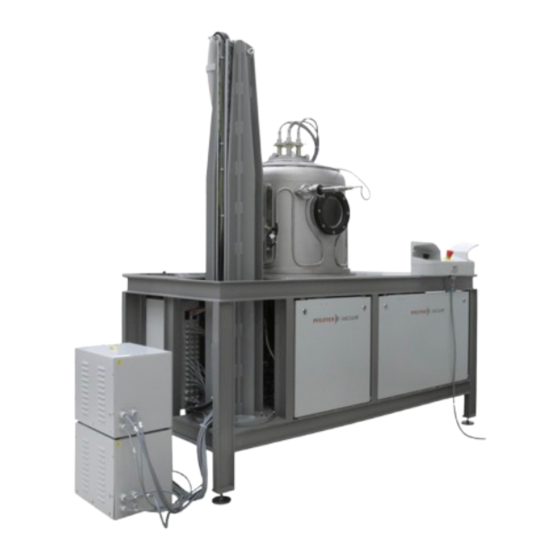
- Page 1 Classic 600 G High Vacuum Coating System PC K00 128 – Thin Film Technology Moscow Operating Instructions...
-
Page 2: Table Of Contents
Contents Contents About this manual ........3 Validity . -
Page 3: About This Manual
1 About this manual 1.1 Validity This manual for the High Vacuum Coating System Classic 600 G is a customer docu- ment of Pfeiffer Vacuum. It describes the functions of the High Vacuum Coating System and provides the most important information for the safe use of the system. -
Page 4: Abbreviations Used
About this manual NOTE Order or note Prompt for activity or information about features that can cause damage to the product if they are disregarded. Pictograph definitions Prohibition of an action or activity in connection with a source of danger, the disregarding of which may result in serious accidents. -
Page 5: Safety
• The High Vacuum Coating System Classic 600 G may be operated, serviced and maintained only by trained and instructed staff. These staff members must have received special instruction regarding the dangers that can occur. -
Page 6: Safety Equipment
Located on the operator panel on the front of the High Vacuum Coating System Classic 600 G is a red mushroom head button that, when pressed, moves the system into a safe condition. There is a second Emergency Stop button with the same function at the control panel for opening and closing the bell. -
Page 7: Proper Use
• Proper use also involves compliance with the installation, start-up, operation and maintenance regulations specified by the manufacturer. • The High Vacuum Coating System Classic 600 G is designed as a single workstation. 2.3 Improper use • Improper use refers to the use of the system for any purpose other than that described above. -
Page 8: Transport And Storage
Transport and storage 3 Transport and storage 3.1 Unpacking / repacking The system is split into segments for transportation and secured in transportable wooden holders. Individual parts are packed securely in transport crates. NOTE Disposal of packaging materials The wooden holders for transporting system components cannot be reused after unpacking. -
Page 9: Product Description
The information on the rating plate helps towards safe identification of the system and when communicating with Pfeiffer Vacuum should be to hand and used at all times. The rating plate is clearly visible on the rear or side covering of a control cabinet. -
Page 10: Construction And Function
Product description 4.2 Construction and function The High Vacuum Coating System Classic 600 G basically consists of a vacuum system, a process chamber as well as supply facilities and a control cabinet. The individual com- ponents are mounted on a section frame structure and wired to each other. All operating elements needed to operate the system are located at the front of the control cabinet. - Page 11 13 Substrate holder Boat 1 (position 4) 14 Substrates The following coating equipment is provided for the Coating System Classic 600 G: • 1 Ion source (position 1) • 1 Sputter source 4" (position 2) • 1 Sputter sources 1" for non-magnetizable target materials such as aluminum (position 3) •...
-
Page 12: Media Supply
Control The function of the coating system Classic 600 G was tested by us prior to delivery. The pump system is controlled via the PLC. 4.3 Media supply... -
Page 13: Process Gas
Product description Fig. 5: Water connection Pressure relief valve Recipient Pressure reducer Boat 1 and 2 Cold water supply line Sputter source 4" Hot water supply line 10 Sputter source 1" (magnetizable) Cold water return line Sputter source 1" (not magnetizable) Hot water return line 12 Compressed air shut-off valve Process gas... -
Page 14: Venting Gas
Product description Venting gas Instead of ambient air, venting can be carried out using an alternative gas, typically oxy- gen or argon. This minimises the amount of moisture admitted to the process chamber as it is being vented. The appropriate connection is located at the venting valve in the rack below the vacuum chamber. -
Page 15: Display And Operation Elements
Product description 4.4 Display and operation elements The operating and control elements in the control cabinet are used to operate the coating system. These enable control of the following process components: • Pump system • Ion sources • Boats • Sputter source •... -
Page 16: User Interface
General Information This chapter gives an overview of the menu guidance on the user interface of the Coating System Classic 600 G. The function and operation of the coating system are described in Chapter 6 "Operation". The system is operated via various menus on different menu levels. The buttons at the bottom of the screen are used to switch back and forth among the menus. - Page 17 Product description When you press the "right" arrow button, the following screen opens. You can switch the hot or cold water supply for the individual coating devices on or off here. Always make sure that the water supply is switched on for the coating source that is to be used in the process.
- Page 18 Product description Here you can set the assignment of the process gases to the individual coating devices and can open or close the respective valves. Menu "Parameter" The individual parameters of the coating system can be set or viewed in the "Parameters" menu.
- Page 19 Product description NOTE Risk of damage due to improper operation If the selected delay for shutting off the water is too short, the temperature of the sources when the system is switched off could still be so high that the sources sustain damage.
- Page 20 Product description "Rotarydrives" screen In the same way as on the main menu screen, you can assign the coating source, sub- strate and mask to one another here. You can also set the rotary drives for rotating the substrate and mask and their alignment with each other here. The set value for the speed at which the rotary drives rotate is displayed in the white fields "Rot.
- Page 21 Product description "Pumpstation" screen The settings for pumping out or venting the vacuum chamber are made here. • Release P6 on: Pressure at gauge M1 at which the turbopump is switched on. The actual pressure is displayed in the coloured field. •...
- Page 22 Product description Menu "Data log" While the coating system is in operation, all events are logged and are saved to an SD card. These events can be viewed in the "Data log" menu and can be saved to an exter- nal USB stick for further evaluation.
- Page 23 Product description Menu "User" In the "User" menu, you can view various information about the stored users and can log users on or off. Press the button "User". To log on a user, press the "Logon" button. The drop-down menu "Logon" then opens. ...
-
Page 24: Installation
Installation After the cause of the alarm has been rectified, press the "Acknowledge" button to cancel the error message. 5 Installation 5.1 Installation location The installation location is to be chosen so that components that need servicing are freely accessible at all times. -
Page 25: Assembly
Installation 5.3 Assembly The system is set up, assembled and commissioned by Pfeiffer Vacuum. All base param- eters of the vacuum pump and measuring system and also control are preset and should only be changed by agreement with the manufacturer. -
Page 26: Connections
Installation 5.4 Connections The coating system internal connections are basically fitted with quick couplings and are ready set up. Water connection The complete cooling water system is connected ready for operation. Make the cooling and hot water connection at the labelled inlets and outlets. ... -
Page 27: Electrical Connection
Installation WARNING High pressure in the exhaust line! Injury hazard from bursting parts. Danger of damage to components. Do not obstruct external exhaust lines with anything that might block them off. Design cross-sections of the exhaust lines at least equivalent to the nominal width of the vacuum pump inlet flange. -
Page 28: Operation
After venting the process chamber: Shut down the PC by pressing the appropriate button in the visualisation. Switch off the complete Coating System Classic 600 G by placing the master switch in the "0" position. In an emergency: ... -
Page 29: Operation Of The System
Operation 6.3 Operation of the System Conditions For safety reasons, process operations is safeguarded by the mechanical safety circuit and the following parameters: • Bell is closed • Pump system running • Vacuum in vacuum chamber < 100 mbar • Vacuum chamber cooling water flow o.k. •... -
Page 30: Process Operation
(see overall documentation). WARNING The process-relevant parameters in the control units of the Classic 600 G may only be changed by duly authorized employees of the user. NOTE All power supply systems are safety-monitored. -
Page 31: Maintenance
Pfeiffer Vacuum Service. WARNING Pfeiffer Vacuum will be released from all warranty and liability claims if the customer makes any changes without prior agreement. NOTE Create safe work conditions Before most upkeep and maintenance work the system must be brought to a safe condition. -
Page 32: Cleaning And Decontamination
Maintenance NOTE We recommend that the user determine maintenance intervals in consultation with the manufacturer’s specialists. 7.2 Cleaning and decontamination Cleaning agents The manufacturer recommends the use of industrial alcohol or ethyl alcohol as a clean- ing agent. WARNING Cleaning agents can lead to health and environmental damage. When using cleaning agents, note the relevant regulations and adhere to protective measures with regard to handling and disposal. -
Page 33: Maintenance Tasks That Can Be Carried Out
Checking operating Fill level fluids Pfeiffer Vacuum rotary vane pumps are operated as standard with the organic operating fluid and lubricant P3. Shut down the system. Switch off the main switch. Dismantle metal casing in front of the vacuum pumps. -
Page 34: Decommissioning
8 Decommissioning Decommissioning of a Pfeiffer Vacuum System should be carried out only according to the recommendation of the Pfeiffer Vacuum Service. See also the notes on shutdown of components in the individual operating manuals and chapter 3.3 in this manual. -
Page 35: Service
A detailed offer regarding the articles needed can be worked out accordingly. Spare part lists Spare part lists for Pfeiffer Vacuum Systems can be found attached to the full documen- tation. 9.4 Repair / Exchange If a repair is required, the following possibilities exist: •... - Page 36 "Free from contaminants" on the equipment or in the accompanying papers. • "Contaminants" are: Materials and preparations in accordance with EU directive of 18.09.1979, article 2. Service address Pfeiffer Vacuum GmbH Berlinerstr. 43 D-35614 Asslar Telephone+49 6441 802 -1192 +49 6441 802 -1199 Internet: http://www.pfeiffer-vacuum.de...
-
Page 37: Technical Data
Technical Data 10 Technical Data Installation Unit Classic 600 G Diameter of the vacuum chamber bell Rack cabinet (W x D x H) 1200 x 800 x 2100 Overall system (W x D x H) 3091 x 1963 x 2100 Weight approx. - Page 38 Technical Data Noise emission Unit Volume in operation db(A) < 85...
-
Page 39: Notes
Notes 11 Notes... - Page 40 Notes...
-
Page 41: Declaration Of Conformity
EC directive Machinery 2006/42/EC, the EC directive Electromagnetic Compatibility 2014/30/EU and the EC directive Low Voltage 2014/35/EU. The agent responsible for compiling the technical documentations Mr. Andreas Würz, Pfeiffer Vacuum GmbH, Berliner Str. 43, 35614 Asslar. High Vacuum Coating System Classic 600 G PC K00 128... - Page 42 Leading. Dependable. Pfeiffer Vacuum stands for innovative and custom Customer Friendly vacuum solutions worldwide. For German engineering art, competent advice and reliable services. Ever since the invention of the turbopump, we´ve been setting standards in our industry. And this claim to leadership will continue to drive us in the future.
Need help?
Do you have a question about the Classic 600 G and is the answer not in the manual?
Questions and answers