
Subscribe to Our Youtube Channel
Related Manuals for Pfeiffer Vacuum FullRange ITR 90


Summary of Contents for Pfeiffer Vacuum FullRange ITR 90
- Page 1 A P A S S I O N F O R P E R F E C T I O N ITR 90 FullRange® Bayard-Alpert Gauge Operating Instructions...
-
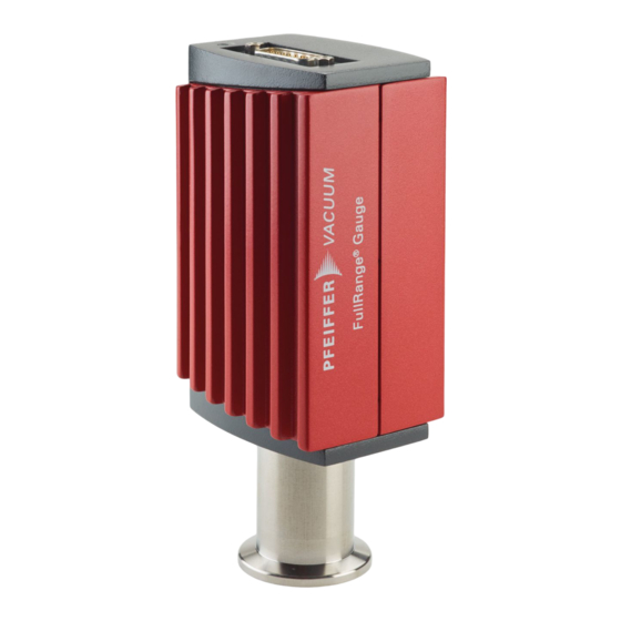
Page 2: Product Identification
They must not be used for measuring flammable or combustible gases in mixtures containing oxidants (e.g. atmospheric oxygen) within the explosion range. The gauges can be operated in connection with a Pfeiffer Vacuum controller or with other control devices. Functional Principle Over the whole measuring range, the gauge has a continuous characteristic curve and its measuring signal is output as logarithm of the pressure. -
Page 3: Table Of Contents
3.1.1 Making the Flange Connection 3.1.2 Removing and Installing the Electronics Unit 3.1.3 Using the Optional Baffle 3.2 Electrical Connection 3.2.1 Use With Pfeiffer Vacuum Gauge Controllers 3.2.2 Use With Other Controllers 4 Operation 4.1 Measuring Principle, Measuring Behavior 4.2 Operational Principle of the Gauge 4.3 Putting the Gauge Into Operation... -
Page 4: Safety
Communicate the safety instructions to other users. 1.4 Liability and Warranty Pfeiffer Vacuum assumes no liability and the warranty becomes null and void if the end-user or third parties • disregard the information in this document •... -
Page 5: Technicale Data
(PELV). The connection to the gauge has to be fused (Pfeiffer Vacuum controller fulfill these requirements). Operating voltage at the ITR 90 +24 VDC (20 … 28 VDC) ripple max. - Page 6 Sensor cable Electrical connector D-Sub, 15-pin, male (→ 13) Cable for ITR 90 Analog values only Without degas function 4 conductors plus shielding Analog values With degas function 5 conductors plus shielding Analog values With degas function And RS232C interface 7 conductors plus shielding Max.
- Page 7 Dimensions [mm] 4-40UNC 2B 4-40UNC 2B DN 25 ISO-KF DN 40 CF-R BG 5040 BEN (2015-12) ITR90.oi...
-
Page 8: Installation
3 Installation 3.1 Vacuum Connection DANGER DANGER: overpressure in the vacuum system >1 bar Injury caused by released parts and harm caused by escaping process gases can result if clamps are opened while the vacuum system is pressurized. Do not open any clamps while the vacuum system is pressurized. Use the type of clamps which are suited to overpressure. -
Page 9: Making The Flange Connection
3.1.1 Making the Flange Connection Procedure It is recommended not to apply any vacuum grease. The protective lid will be needed for maintenance. 3.1.2 Removing and Installing the Electronics Unit Required tool • Allen key, size 2.5 mm Removing the electronics unit ... -
Page 10: Using The Optional Baffle
Remove the electronics unit without twisting it. Removal of the electronics unit is completed. Installing the electronics unit Place the electronics unit on the sensor (3) (be careful to correctly align the pins and notch (4)). Slide the electronics unit in to the mechanical stop and lock it with the hexa- gon socket set screw (1). - Page 11 Procedure Carefully remove the grid with tweezers. Carefully place the baffle onto the sensor opening. Using a pin, press the baffle down in the center until it catches. The baffle is now installed (Installation of the gauge → 8). BG 5040 BEN (2015-12) ITR90.oi...
-
Page 12: Electrical Connection
Carefully remove the baffle with the screwdriver. 3.2 Electrical Connection 3.2.1 Use With Pfeiffer Vacuum See Pfeiffer Vacuum sales literature and data sources for controllers and our range of sensor cables on our internet home page (www.pfeiffer-vacuum.com). Gauge Controllers Procedure ... - Page 13 Sensor cable connection ITR 90 ITR 90 RS232C Measuring signal – Degas 1.25AT 24 V – Identification 42kΩ Electrical connection Pin 2 Signal output (measuring signal) 0 … +10 V Pin 5 Supply common, GND Pin 7 Degas on, active high +24 VDC Pin 8 Supply...
- Page 14 Plug the sensor connector into the gauge and secure it with the locking screws. Connect the other end of the sensor cable to the connector of the instru- ment or gauge controller you are using. The gauge can now be operated via analog and RS232C interface. BG 5040 BEN (2015-12) ITR 90...
-
Page 15: Operation
4 Operation 4.1 Measuring Principle, The ITR 90 vacuum gauge consist of two separate measuring systems (hot cathode Bayard-Alpert (BA) and Pirani). Measuring Behavior Bayard-Alpert The BA measuring system uses an electrode system according to Bayard-Alpert which is designed for a low x-ray limit. The measuring principle of this measuring system is based on gas ionization. -
Page 16: Operational Principle Of The Gauge
Schematic The bridge voltage U is a measure for the gas pressure and is further processed electronically (linearization, conversion). Measuring range The ITR 90 gauge s continuously cover the measuring range 5×10 mbar … 1000 mbar. • The Pirani constantly monitors the pressure. •... -
Page 17: Degas
4.4 Degas Contamination Gauge failures due to contamination or wear and tear as well as ex- pendable parts (e.g. filaments) are not covered by the warranty. Deposits on the electrode system of the BA gauge can lead to unstable measure- ment readings. - Page 18 Synchronization Synchronization of the master is achieved by testing three bytes: Byte No Function Value Comment Length of data string Set value Page number (For ITR 90) Check sum of bytes No 1 … 7 0 … 255 Low byte of check High order bytes are ignored in the check sum.
-
Page 19: Input String (Receive)
Example The example is based on the following output string: Byte No Value The instrument or controller (receiver) interprets this string as follows: Byte No Function Value Comment Length of data (Set value) string Page number ITR 90 Emission = off Status Pressure unit = mbar No error... -
Page 20: Deinstallation
5 Deinstallation DANGER DANGER: contaminated parts Contaminated parts can be detrimental to health and environment. Before beginning to work, find out whether any parts are contami- nated. Adhere to the relevant regulations and take the necessary pre- cautions when handling contaminated parts. Caution Caution: vacuum component Dirt and damages impair the function of the vacuum component. -
Page 21: Maintenance, Repair
6 Maintenance, Repair 6.1 Maintenance DANGER DANGER: contaminated parts Contaminated parts can be detrimental to health and environment. Before beginning to work, find out whether any parts are contami- nated. Adhere to the relevant regulations and take the necessary pre- cautions when handling contaminated parts. -
Page 22: Zero Point Adjustment
Insert the pin through the opening marked <FULL SCALE> and push the button inside for at least 5 s. The gauge is automatically adjusted (≈10 s). The gauge is now adjusted at atmospheric pressure. 6.2.2 Zero Point Adjustment A zero point adjustment is recommended •... -
Page 23: What To Do In Case Of Problems
6.3 What to Do in Case of In the event of a fault or a complete failure of the output signal, the gauge can easily be checked. Problems Required tools / material • Voltmeter / ohmmeter • Allen key, size 2.5 mm •... -
Page 24: Replacing The Sensor
View on sensor pins Hot cathode ca. 0.15 Ohm Not connected Pirani sensor 1 ca. 37 Ohm Pirani sensor 2 ca. 37 Ohm Anode GND (connected to sensor housing) Ion collector Correction All of the above faults can only be remedied by replacing the sensor (→ 24). 6.4 Replacing the Sensor Replacement is necessary, when •... -
Page 25: Options
7 Options Ordering No. Bake-out extension 100 mm PT 590 300-T PT 120 124-T Baffle DN 25 ISO-KF / DN 40 CF-R (→ 10) 8 Spare Parts When ordering spare parts, always indicate: • All information on the product nameplate •... -
Page 26: Returning The Product
Contaminated products (e.g. radioactive, toxic, caustic or biological hazard) can be detrimental to health and environment. Products returned to Pfeiffer Vacuum should preferably be free of har- mful substances. Adhere to the forwarding regulations of all involved countries and forwarding companies and enclose a duly completed declaration of contamination (form under "www.pfeiffer-vacuum.com"). -
Page 27: Appendix
Appendix Relationship Output Signal – Pressure (U - 7.75) / 0.75 + c Conversion formulae p = 10 U = 0.75 × (log p - c) + 7.75 where [mbar] [Pa] [Torr] -0.125 Conversion curve BG 5040 BEN (2015-12) ITR90.oi... -
Page 28: B: Gas Type Dependence
Conversion table Output signal U Pressure p [mbar] [Torr] [Pa] 0.3 / 0.5 Sensor error (→ 23) 0.51 … 0.774 Inadmissible range 0.774 5×10 3.75×10 5×10 1.00 1×10 7.5×10 1×10 1.75 1×10 7.5×10 1×10 1×10 7.5×10 1×10 3.25 1×10 7.5×10 1×10 4.00... -
Page 29: C: Literature
[1] www.pfeiffer.vacuum.com Literature Instruction Sheet ® FullRange Bayard-Alpert Gauge ITR 90 BG 5039 BDE Geman BG 5039 BEN English Pfeiffer Vacuum GmbH, D–35614 Asslar, Deutschland BG 5040 BEN (2015-12) ITR90.oi... - Page 30 Notes BG 5040 BEN (2015-12) ITR 90...
- Page 31 Notes BG 5040 BEN (2015-12) ITR90.oi...
- Page 32 A P A S S I O N F O R P E R F E C T I O N Pfeiffer Vacuum stands for innovative and custom Vacuum solutions vacuum solutions worldwide, technological perfection, from a single source competent advice and reliable service.
Need help?
Do you have a question about the FullRange ITR 90 and is the answer not in the manual?
Questions and answers