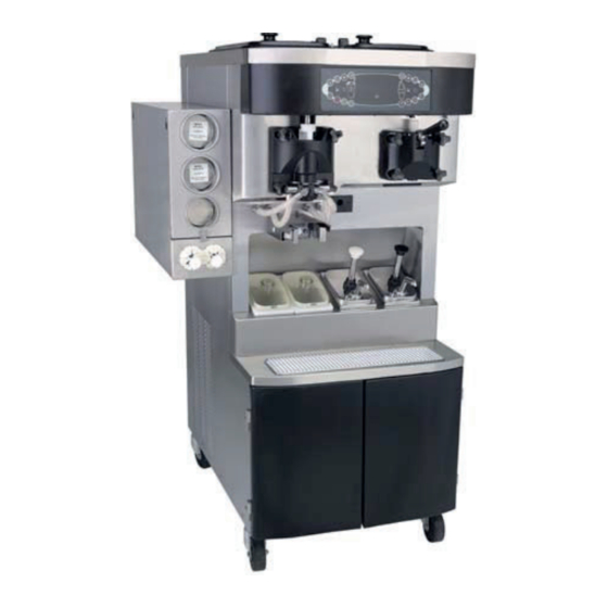
Taylor C602 Original Service Instructions
Combination shake/ soft serve freezer
Hide thumbs
Also See for C602:
- Service manual (114 pages) ,
- Manual (102 pages) ,
- Pocket manual (92 pages)

Related Manuals for Taylor C602


Summary of Contents for Taylor C602
- Page 1 SERVICE MANUAL Model C602 Combination Shake/ Soft Serve Freezer Original Service Instructions 057888-S 1/07 (Original Publication) (Updated 7/14/2023)
- Page 2 CAUTION: Information in this manual is intended to be used by Taylor service technicians only. Note: Continuing research results in steady improvements; therefore, information in this manual is subject to change without notice. Note: Only instructions originating from the factory or its authorized translation representative(s) are considered to be the original set of instructions.
-
Page 3: Table Of Contents
Model C602 Specifications ........ - Page 4 Table of Contents Beater Door Assembly—Shake Side ........4-10 Beater Door Assembly—Soft Serve Side .
-
Page 5: Section 1: Introduction
Section 1: Introduction • Safety • Model C602 Specifications • General Installation Instructions • Environmental Notices Introduction Model C602... -
Page 6: Safety
INTRODUCTION Safety We at Taylor are committed to manufacturing safe operating and serviceable machines. The many built-in safety features that are part of all Taylor machines are WARNING! Avoid injury. aimed at protecting operators and trained service • DO NOT attempt any repairs unless the main technicians alike. - Page 7 Failure to comply may result in personal injury or damage to the machine. WARNING! Only install this machine in a location where its use and maintenance is restricted to trained personnel. Failure to comply may result in personal injury. Introduction Model C602...
-
Page 8: Model C602 Specifications
INTRODUCTION Model C602 Specifications Freezing Cylinders Electrical Shake side: One 7 qt. (6.6 L) capacity. Standard is 208/230-60-3; however, other electrical characteristics are available. Each machine requires Soft serve: One 3.4 qt. (3.2 L) capacity. electrical service: Mix Hopper Three-phase maximum fuse size: 45A Minimum wire ampacity: 35A Two 20 qt. - Page 9 INTRODUCTION Figure 1-1 Introduction Model C602...
-
Page 10: General Installation Instructions
NOTICE! Only trained, authorized service technicians Uncrate the machine and inspect it for damage. Report should install this machine. Failure to comply will void the any damage to your Taylor distributor. factory warranty. For Indoor Use Only: This machine is designed to operate indoors, under normal ambient temperatures of ... -
Page 11: Electrical Connections
10 mA, particularly when disconnected or not used for long periods, or during initial installation, shall have protective devices, to protect against the leakage of current such as a GFI, installed by the authorized personnel to the Introduction Model C602... -
Page 12: Beater Rotation
• If the supply cord is damaged, it must be 6. Press the WASH key to discontinue beater motor replaced by a Taylor service technician in order operation. to avoid a hazard. • Secure the supply cord ground lead to the... - Page 13 If rotation is not correct, refer to the wiring diagram on the pump motor and re-wire accordingly. NOTICE! Taylor reminds technicians to be Refrigerant aware of government laws regarding refrigerant recovery, recycling, and reclaiming systems. If you have any questions regarding these laws, please contact the factory service department.
-
Page 14: Compressor Warranty Disclaimer
INTRODUCTION Compressor Warranty Disclaimer It should be noted that Taylor does not warrant the refrigerant used in its machines. For example, if the The refrigeration compressor(s) on this machine are refrigerant is lost during the course of ordinary service to... -
Page 15: Environmental Notices
The user is responsible for delivering the machine to the appropriate collection facility, as specified by your local code. For additional information regarding applicable local disposal laws, please contact the municipal waste facility and/or local authorized Taylor distributor. 1-11 Introduction Model C602... - Page 16 INTRODUCTION Notes: 1-12 Introduction Model C602...
-
Page 17: Section 2: Controls
• Timers • Glycol • Setting Viscosity • Portion Control (Shake) • Adjustable Draw Handle • Universal Control Overview • Universal Control • LONWorks® Gateway • Electrical System • Shake Draw • Shake Dispensing Alignment Procedure • Syrup Controls Model C602... -
Page 18: Running Specifications
CONTROLS Running Specifications Pressures/Temperatures High-Side (Discharge) The following are the Taylor recommended settings for High-side pressure varies for air-cooled machines, various components in the Model C602. (See depending on the ambient temperature. “Refrigeration System Schematic” on page 2-5.) Table 2-1... -
Page 19: Remote Monitoring Commissioning
Gateway. 2. From a user device (laptop, cellphone, tablet, etc.) connect to the taylor-gw access point through the Wi-Fi setting on the device. a. This access point may not be broadcast so the user may have to use the Add Network function. - Page 20 Confirm the cable between the gateway and UVC4 boards is connected properly and not damaged. • Confirm UVC4 is functioning correctly. • Confirm the UVC4 has the correct software version for remote monitoring system: • C602: Minimum version 2.03 Controls Model C602...
-
Page 21: Refrigeration System Schematic
CONTROLS Refrigeration System Schematic Figure 2-5 Controls Model C602... -
Page 22: Control Panel Functions
Illuminates when the mix hopper has a low supply of mix; should be refilled as soon as possible. Indicator Light-Mix Out Illuminates when the mix hopper has an insufficient supply of mix to operate the freezer. The Auto mode will be locked out and the machine will be placed in the Standby mode. Controls Model C602... - Page 23 = Topping Heater-Right To better communicate in the international arena, the words on many of the operator keys have been replaced by symbols to indicate their function. Your Taylor machine = Calibrate is designed with these international symbols. The following chart identifies key functions:...
- Page 24 Initializing ..Config Data Initializing ..System Data During the initializing sequence, if the system detects corrupt data, the following display will alert the operator that the control settings have changed: Controls Model C602...
- Page 25 Hopper and freezing cylinder temperatures are Figure 2-15 above 60°F (15.6°C). When the temperature of the mix is above 130°F c. Both freezer doors were removed concurrently. (54.4°C), the screen will display HOT PRODUCT. (See Figure 2-16.) Figure 2-16 Controls Model C602...
-
Page 26: Freezer Lockout
Soft Lock: If a heat treatment cycle has not been initiated within the last 24 hours, a soft lock failure will Figure 2-18 occur. A soft lock allows the operator to correct the cause of the soft lock. The operator has the option of either 2-10 Controls Model C602... -
Page 27: Power Switch Off
28-day timer, or the start of the last successful heat treatment cycle. (Auto Heat Time was advanced, a power loss was experienced at the time the cycle was to occur, or a heat treatment cycle failure not 2-11 Controls Model C602... - Page 28 The fault description can also be found in the Manager and Service Menus. (See “FAULT DESCRIPTION” on page 2-21.) Note: A record of heat cycle data and lockout history can be found in the Manager and Service Menus. (See “LOCKOUT HISTORY” on page 2-22.) 2-12 Controls Model C602...
-
Page 29: Service Menu
The Flavor Selection key decreases the value above the cursor and scrolls downward in text displays. The Calibration key advances the cursor position to the right and is used to select menu options. 2-13 Controls Model C602... -
Page 30: Service Menu Options
Manager Menu. • EXIT FROM MENU • SYRUP CALIBRATION • VERIFY CALIBRATION • SERVINGS COUNTER • SET CLOCK • AUTO HEAT TIME • AUTO START TIME • STANDBY MODE • BRUSH CLEAN CYCLE • MIX LEVEL AUDIBLE 2-14 Controls Model C602... -
Page 31: Syrup Calibration
3. Select the corresponding favor selection. Syrup will ask, “Are you sure?” (See Figure 2-35.) flow into the cup for 5 seconds (7 seconds for triple thick shake syrup) and then automatically stop flowing. Figure 2-35 2-15 Controls Model C602... - Page 32 Other = Any draw termination that is not Pyro, Time, or Oper. Move the cursor (>) to Details, and then select the Example: Power switch turned to OFF while product is Calibration key .. (See Figure 2-37.) dispensing. Figure 2-37 2-16 Controls Model C602...
-
Page 33: Set Clock
The DAYLIGHT SAVING TIME feature, when Selection key with the cursor under the hour enabled, will automatically adjust the control clock for position. daylight saving time. 5. Move the cursor to minutes by selecting the Calibration key 2-17 Controls Model C602... - Page 34 Figure 2-44 return to the menu. 5. Once the appropriate month has been entered, scroll to the appropriate week. Press the Calibration to accept the selection. (See Figure 2-45.) Figure 2-45 2-18 Controls Model C602...
- Page 35 AUTO HEAT TIME screen. ) or decreasing (Flavor Selection key the hour setting above the cursor. 6. Select the Calibration key to exit the screen and return to the menu. 2-19 Controls Model C602...
-
Page 36: Standby Mode
Figure 2-55.) Figure 2-53 4. Discontinue Standby operation for either side by exiting the menu and select the Auto mode. Figure 2-55 Always comply with local guidelines on the number of days allowed between brush-clean cycles. 2-20 Controls Model C602... -
Page 37: Fault Description
Selecting the Calibration key when faults are displayed clears the faults, if faults were corrected on returning to the menu screen. Listed below are the various messages which will appear, along with an explanation for the corrective action. 2-21 Controls Model C602... - Page 38 45°F (7°C) more than 1 hour. (L/R) HPR>59F (15C) - The mix temperature in the left or right hopper exceeded 59°F (15°C). (L/R) BRL>59F (15C) - The mix temperature in the left or right barrel exceeded 59°F (15°C). 2-22 Controls Model C602...
-
Page 39: Fault History
Figure 2-62.) (L/R) HPCO Compressor - The left or right high-pressure switch contacts have opened. (L/R) Glycol Therm Bad - The left or right glycol thermistor probe is reading over 200°F (93°C). Figure 2-62 2-23 Controls Model C602... - Page 40 115 PRODUCT DOOR OFF minutes. A product door is not in place or is loose. Select the Auto key to advance to the next page or the Flavor Selection key to view the previous page. 2-24 Controls Model C602...
- Page 41 An L or an H displayed to the left of the temperature reading indicates the temperature was the lowest or highest recorded during the phase. 3. With the cursor (>) on the Display record line, select the Calibration key 2-25 Controls Model C602...
- Page 42 Exit and select the Calibration key The average heat treatment cycle will contain approximately 40 samples of the four temperature zone screens. 10. When the final sample in the phase is displayed, the Heat Cycle results screen can be selected. 2-26 Controls Model C602...
-
Page 43: System Information
(B.O.M.) and machine serial number. The model and serial number information must be entered in the EDIT UNIT ID screens in the Service Menu in order to display the machine details in the system information screen. (See Figure 2-68.) Figure 2-68 2-27 Controls Model C602... -
Page 44: Standby Temperature
Figure 2-74.) display all temperatures. (See Figure 2-72.) Figure 2-74 Figure 2-72 3. Select the Calibration key to save the setting and return to the Service Menu. 2-28 Controls Model C602... - Page 45 Heat and Hold phases of the heat treatment cycle. 2. Select the Calibration key to save the setting and return to the Service Menu. 2-29 Controls Model C602...
-
Page 46: Viscosity Setting
When the beater motor is off, this value is zero. Figure 2-80 Note: A Hedlund (HD) is a Taylor factory defined unit of measure representing the relative product viscosity (thickness). Product in the shake machine is normally set at a viscosity ranging from 4,000 HD to 7,500 HD to accomplish a neutral frozen product temperature around 23°F - 26°F (-5°C to -3.3°C). - Page 47 2. Advance to the next screen for the right-side setting Calibration key . (See Figure 2-85.) or return to the service menu by selecting the Calibration key . (See Figure 2-83.) Figure 2-85 Figure 2-83 2-31 Controls Model C602...
- Page 48 2. Select the Calibration key to save the setting The range for the pump off delay is 0 sec. to 30 sec. and and advance to the whitespot setting for the next is adjustable in 1-second intervals. flavor. 2-32 Controls Model C602...
- Page 49 The following screen is displayed by selecting this option. (See Figure 2-91.) Figure 2-93 3. Enter the serial number from the machine's data label in the same manner as the BOM. Figure 2-91 2-33 Controls Model C602...
-
Page 50: Select Language
2. When the raw viscosity is between 1,000 to 1,500, an audible tone will sound at regular intervals. The target setting is the middle of the audible tone range. 2-34 Controls Model C602... - Page 51 1. Select the Auto key to increase the reverse time setting or the Flavor Selection key to decrease the setting. 2. Select the Calibration key to advance to the Figure 2-100 motor speed setting screen for the next flavor. 2-35 Controls Model C602...
- Page 52 Four service programmable timers (delays) have been motor is activated. The spinner will run prior to the incorporated into the C602 software, beginning with draw valve opening. Recommended setting: version 1.10. Each timer may be programmed for a delay 0.3 sec.
-
Page 53: Manual Control
RIGHT GLYCOL SOLENOID following screen: • RIGHT SYRUP HEATER • GLYCOL PUMP • GLYCOL HEATER • SPINNER MOTOR • AGITATOR MOTOR The freezer must be off to use this feature. Figure 2-109 (See Figure 2-106.) Figure 2-106 2-37 Controls Model C602... -
Page 54: Reset To Defaults
Selecting this option in the menu will display a screen asking ARE YOU SURE? (See Figure 2-110) Figure 2-110 Moving the cursor to YES and selecting the Calibration key restores all factory default values. 2-38 Controls Model C602... -
Page 55: Heat Treatment
The Heat Phase Timer determines the maximum the machine is operating in the Standby mode. allowable amount of time the machine can remain in the Heat phase of the heat treatment cycle. If the timer exceeds 90 minutes, the machine will lockout. 2-39 Controls Model C602... -
Page 56: Heat Treatment Graph
turned off. The timed cycle continues in this manner until 60 minutes. the Cool phase is complete. Figure 2-111 2-40 Controls Model C602... -
Page 57: Timers
Soft Serve—The mix pump will run for 30 seconds Note: This timer is adjustable from 2 days to 28 days. anytime the machine is placed in the Auto mode. 2-41 Controls Model C602... - Page 58 Cool Phase Timer The Cool Phase Timer determines the maximum allowable time the machine can remain in the Cool phase of the heat treatment cycle (120 minutes). If the timer exceeds 120 minutes, the machine will lockout. 2-42 Controls Model C602...
-
Page 59: Glycol
Auto, Standby, or Heat mode. The agitator is driven by a marked W4. The jumper will activate the glycol pump motor and belt(s). and open the glycol solenoids (if applicable). The glycol existing in the accumulator will be pumped through the glycol system. 2-43 Controls Model C602... - Page 60 8. Once the system is fully drained, remove the service 4. Check for glycol mixture leaks. hose and replace the access cap. Replace the outlet line of the glycol pump to proper position. Remove the pliers. Figure 2-113 2-44 Controls Model C602...
- Page 61 CONTROLS Glycol Path (Rear View) Figure 2-114 2-45 Controls Model C602...
-
Page 62: Setting Viscosity
4,000 HD. To adjust the serving viscosity, it may be necessary to raise or lower the HD setting. Adjust in increments of 100 HDs. Note: Be sure that the syrups are correctly calibrated before determining the proper serving viscosity. 2-46 Controls Model C602... -
Page 63: Portion Control (Shake)
0.2VDC when a cup-full is not sensed, and makes a momentary 5VDC pulse when a cup-full is sensed. Pin 2 = BLACK: DC ground connection. Pin 4 = RED: The 12VDC power supply from the interface board. 2-47 Controls Model C602... -
Page 64: Adjustable Draw Handle
10 seconds. To Increase the flow rate, tighten the screw. To decrease the flow rate, loosen the screw. After setting the flow rate, tighten the jam nut to secure the adjustment screw. Figure 2-116 2-48 Controls Model C602... -
Page 65: Universal Control Overview
CONTROLS Universal Control Overview Control Overview - UVC3 Figure 2-117 2-49 Controls Model C602... - Page 66 CONTROLS Control Overview - UVC4 Figure 2-118 2-50 Controls Model C602...
- Page 67 Communication to Control Panel Interface Board. JP2 Pins See Table on page 2-56. Audible Tone Device Not activated on Model C602. (See Table on page 2-56.) JP3 Pins See Table on page 2-56. JP1 Pins See Table on page 2-56.
- Page 68 CONTROLS Universal Control Board Connections - UVC4 Beginning in January 2011, Taylor started transitioning Note: UVC4 can only be used to replaced UVC3 from the UVC3 to the UVC4. boards. UVC4 is not compatible with UVC1 or UVC2. Figure 2-120...
-
Page 69: Universal Control
There are three sets of pins on the UVC3 board and four sets of pins on the UVC4 board. Refer to the following chart to identify their function. Note: Use Part No. 040084-001 Connector-Programing Shunt to jumper pins. 2-53 Controls Model C602... - Page 70 CONTROLS Inputs/Outputs - C602 Shake Side Table 2-7 J10 Connection at UVC 50 Pin Cable J2 Connection at Interface Pin 2 Receives the viscosity (Hedlund) reading. Pin 4 Signals the draw solenoid to operate (hold circuit). Pin 6 Signals the beater motor to operate.
- Page 71 CONTROLS Inputs/Outputs - C602 Sundae Side Table 2-8 J11 Connection at UVC 50 Pin Cable J2 Connection at Interface Pin 2 Pin 4 Signals the draw solenoid to operate (opening solenoid). Pin 6 Signals the beater motor to operate. Pin 8 Signals the agitator to operate.
- Page 72 CONTROLS Jumper Pin Function and Configuration Chart Table 2-9 2-56 Controls Model C602...
- Page 73 “RESET TO DEFAULTS” on page 2-38.) recommended. WARNING! DO NOT attempt any repairs unless the main power supply to the machine has been disconnected. Failure to do so can result in severe personal injury from electrical shock. 2-57 Controls Model C602...
-
Page 74: Interface Boards
Power Switch OFF message will There are four sets of pins (W2, W3, W4, W5) on each appear on the screen. (See Figure 2-126.) interface board. (See “Jumper Pin Function and Configuration Chart” on page 2-56.) Figure 2-126 2-58 Controls Model C602... -
Page 75: Motor Speed Control
(See “Control Overview - UVC3” on page 2-49.) The syrup pump motors run at maximum speed in the Prime mode. The universal control calculates the motor speed setting in the syrup Calibration mode and sends the information to the speed control. 2-59 Controls Model C602... - Page 76 Important! (See “UVC4 Electrostatic Discharge and connected to the UVC4 board. Connected at J13 is the Proper Handling Procedures” on page 2-53.) USB cable part number 069023 (1) and connected at J12 is the LON Cable part number 069025 (2). 2-60 Controls Model C602...
- Page 77 When replacing a UVC3 board in the field, adapter Proper Handling Procedures” on page 2-53.) cables are needed. Cable part number 069024 (1) connects to the existing USB cable. Cable part number 069026 (2) connects to the existing LON Cable. 2-61 Controls Model C602...
- Page 78 4. Remove the two screws at the bottom of Panel-Rear-Upper *C602* (066724). 5. Remove the six screws from Cover-Control Box *C602* (066723). 6. Install a jumper onto W2 on the left-side interface board. 7. Reconnect power to the machine and turn the power on.
-
Page 79: Lonworks® Gateway
The gateway is installed in our machine, near the power deactivated. entry point. A separate 40VA transformer and a Corcom filter provide the power to the LON® Gateway, using 2-1/4 in. spade terminals. In the C602, a cable connects 2-63 Controls Model C602... -
Page 80: Electrical System
Heat Component Standby Wash Auto Pump Prime Heat Hold Cool Compressor Beater Motor Spinner Motor (Shake Only) Air/Mix Pump Motor Syrup Pump Glycol Heater Agitator Left Glycol Solenoid Right Glycol Solenoid Glycol Pump Shake Draw Solenoid 2-64 Controls Model C602... - Page 81 Pin 4 for the glycol solenoid. terminal J10.) Pin 2 for the glycol pump motor. Pin 3 for the glycol heater relay coil. Pin 1 for the compressor contactor coil. Pin 2 for the glycol pump. 2-65 Controls Model C602...
- Page 82 (Operation of this solenoid is controlled by the soft serve Once the freezing cylinder and hopper thermistor probes glycol thermistor probe which is connected to terminal (connected to terminal J10 on the interface board) have J10.) been satisfied, the heat treatment cycle will end. 2-66 Controls Model C602...
-
Page 83: Shake Draw
(0.5 second Delay) Stop Spinner Motor J6-T6 / J7-T1 Viscosity Setting Stop Compressor J6-T1 / J7-T7 Achieved - Cycle OFF Stop Beater Motor J6-T7 / J7-T1 Start Off Cycle Stir Timer *Adjustable setting in Service Menu 2-67 Controls Model C602... - Page 84 CONTROLS Shake Draw Solenoid Electrical Circuit With Rectifier Board (Prior to Serial Number K6081879) Figure 2-133 2-68 Controls Model C602...
- Page 85 CONTROLS Shake Draw Solenoid Electrical Circuit - 24V Transformer/Rectifier PCB Figure 2-134 2-69 Controls Model C602...
- Page 86 CONTROLS Shake Draw Solenoid Electrical Circuit - 24V Transformer/IC Rectifier Figure 2-135 2-70 Controls Model C602...
-
Page 87: Draw Solenoid (059462-Cp)
(Part No. 059478 Harness-Rectifier/Relay/ HOLD Circuit: Solenoid). Attach meter leads to the black (center) wire and the brown wire. (Note: The brown wire may be a black/white stripe on some solenoids.) Hold circuit resistance = 1,165.0 ± 58.25 ohms 2-71 Controls Model C602... - Page 88 Under a load condition the voltage will drop slightly. For example, the low voltage output from the rectifier powered by the transformer may drop to 17V to 18V when the solenoid is energized. 2-72 Controls Model C602...
-
Page 89: Shake Dispensing Alignment Procedure
Actuator Plate (See Figure 2-138.) Spinner Motor Bracket Solenoid Valve Spinner Motor Spinner Coupling Bumper Actuator Plate Alignment The actuator plate (lifter) must be centered to fit in the draw valve slot. (See Figure 2-137.) Figure 2-138 2-73 Controls Model C602... - Page 90 The flow rate for the frozen mix will be reduced and the syrup blended in the shake will be greater than the calibrated amount. You may also notice that it takes longer than normal to drain the freezing cylinder when rinsing the machine. Figure 2-140 2-74 Controls Model C602...
-
Page 91: Spinner Motor
3. Position the coupling so the bottom of the spinner is recessed 1/32 in. (0.8 mm) or less in the bottom of the door spout. 4. Retigten the coupling screw. Note: A spinner alignment tool is available to assist with alignment procedures (See Figure 2-143.) 2-75 Controls Model C602... - Page 92 When the draw valve solenoid is properly aligned, the bevel in the alignment tool will line up with the arm bracket. 2-76 Controls Model C602...
-
Page 93: Syrup
A 24VDC motor drives each peristaltic pump. In Auto (See “SYRUP MOTOR SETUP” on page 2-35.) mode, the UVC3 control regulates the motor speed Figure 2-144 2-77 Controls Model C602... - Page 94 Adjust the reverse time to the recommended setting on the chart. 2. Menu Selection: Syrup Calibration Calibrate each flavor using the small chamber on the divided cup. (Taylor Part No. 017203) 2-78 Controls Model C602...
-
Page 95: Additional Operating Tips
1 oz., or improper ribbon cable connection. Chart C: Default Speed 128 Table 2-15 Cal Syrup Time Cal Syrup Time = 5 Seconds = 7 Seconds Motor Time (Seconds) Motor Speed Time Speed (Seconds) 2-79 Controls Model C602... -
Page 96: Calibration Procedure
, the Auto key Figure 2-147 on the shake side, and the Flavor Selection key will be illuminated. (See Figure 2-145.) Press the Calibration key to enter the SYRUP CALIBRATION mode. (See Figure 2-148.) Figure 2-148 Figure 2-145 2-80 Controls Model C602... - Page 97 Verify the level of syrup in the cup. If the measurement is not within the specification, repeat Step 4 for the same flavor until the correct syrup Calibration is achieved. (See Figure 2-150.) Figure 2-150 2-81 Controls Model C602...
- Page 98 Pump key a second time. Note: To cancel the UNFLAVORED DRAW screen, touch the Flavor Selection key to move the cursor (>) to NO, then press the Calibration key Figure 2-152 The following screen will display: Figure 2-153 2-82 Controls Model C602...
-
Page 99: Section 3: Troubleshooting
Section 3: Troubleshooting • General Troubleshooting Guide • Air Mix Pump System Troubleshooting • Peristaltic Syrup System Troubleshooting Guide • Shake Dispensing Mechanism Troubleshooting • Shake Portion Control Troubleshooting • Pyroelectric Sensor Troubleshooting • Bacteria Troubleshooting Troubleshooting Model C602... -
Page 100: General Troubleshooting Guide
Check the adjustment and the water supply. restricted. d. Insufficient airspace around machine. d. Make sure there is sufficient airspace surrounding the machine, (See “Model C602 Specifications” on page 1-4.) e. Refrigerant overcharge. e. Correct the refrigerant charge. f. Blower is faulty. f. Replace the blower. - Page 101 Inadequate lube on draw valve O-rings. b. Lubricate properly. c. Wrong type of lubricant being used. c. Use proper lubricant. Example: Taylor Lube High Performance. 10. Product is not being fed a. Inadequate mix in the hopper (Mix Out light a.
- Page 102 Assemble pump according to instructions in the Operator's Manual. c. Faulty component in mix pump. c. Inspect/replace faulty pump components. d. Freezer has been turned on and off several d. Place the machine in the OFF position only times. when necessary. Troubleshooting Model C602...
- Page 103 29. Symbol selection is a. Defective DEC plate. a. Replace DEC plate. delayed. 30. Erratic brush-clean a. The rectifier guard is not installed. a. Installed the guard to shield the interface countdown display. board from electrical noise. Troubleshooting Model C602...
-
Page 104: Air Mix Pump System Troubleshooting
Malfunctioning draw switch. b. Reposition or replace the microswitch. 6. One pump cannot be a. Soft serve and shake pump parts are mixed up. a. Consult the Operator's Manual for correct assembled. pump assembly combinations. Troubleshooting Model C602... -
Page 105: Peristaltic Syrup System Troubleshooting Guide
The duckbill valve is defective. e. Replace the duckbill valve. f. The draw solenoid does not keep the f. (See “Shake Dispensing Mechanism draw valve raised. Troubleshooting” on page 3-9.) Troubleshooting Model C602... - Page 106 Remove the syrup line from the door when freezer door. the line is not in use. Install a hole plug in the freezer door. d. The shake temperature is too cold. d. The correct temperature of a finished chocolate shake is 22.5°F (-5.8°C). Troubleshooting Model C602...
-
Page 107: Shake Dispensing Mechanism Troubleshooting
Align the actuator place and secure the open (long draw time). bumper screw to the solenoid plunger. b. The draw solenoid is adjusted too low. b. Adjust the draw solenoid to the proper height. (See “Solenoid Valve Height Position” on page 2-74.) Troubleshooting Model C602... - Page 108 Draw solenoid is set too high. g. (See “Solenoid Valve Height Position” on page 2-74.) h. The driven spinner has disengaged h. Adjust the spinner coupling. (See “Spinner from the spinner blade assembly. Motor Alignment Procedures” on page 2-75.) 3-10 Troubleshooting Model C602...
-
Page 109: Shake Portion Control Troubleshooting
The syrup calibration is set too low. c. Calibrate the syrup. d. The portion control sensor lens is dirty. d. Clean the lens. 3-11 Troubleshooting Model C602... -
Page 110: Pyroelectric Sensor Troubleshooting
5. Shake Personality Board (X59072) J2 to Heat Treat Interface Board (X53451) J13 6. Heat Treat Interface Board (X53451) J13 to Heat Treat Interface Board (X53451) J2 7. Heat Treat Interface Board (X53451) J2 to UVC3 J10 (50 pin ribbon cable) 3-12 Troubleshooting Model C602... - Page 111 TROUBLESHOOTING PERSONALITY BOARD - SHAKE Figure 3-1 3-13 Troubleshooting Model C602...
-
Page 112: Bacteria Troubleshooting
3. Worn, damaged, or cracked a. Provide a food-grade lubricant (Example: Taylor Lube). parts. b. Inspect O-rings for holes or tears. O-rings, seals and other wear items must be supplied by the freezer company to meet food industry standards. - Page 113 45°F (7.2°C) will allow cell division in as little as 1 hour. f. Once the mix is placed in the hopper, covers must be properly installed to maintain adequate refrigeration and to prevent airborne contaminants from entering the mix. 3-15 Troubleshooting Model C602...
- Page 114 TROUBLESHOOTING Notes: 3-16 Troubleshooting Model C602...
-
Page 115: Section 4: Parts
Section 4: Parts • Parts Warranty Explanation • Main Exploded View • Accessories Parts Model C602... -
Page 116: Parts Warranty Explanation
Taylor service technician. Taylor reserves the right to deny warranty claims on machines or parts if unapproved parts or refrigerant were installed in the machine, system modifications were performed beyond factory recommendations, or it is determined that the failure was caused by neglect or abuse. -
Page 117: Main Exploded View
PARTS Main Exploded View Figure 4-1 Parts Model C602... - Page 118 Motor-1.0 HP*Left 013102-33 Condenser-AC 12L X 18H X 055813-2 3.12T-5*Right/Soft Serve Motor-1.5 HP*Right 021522-33 Receiver A.-REFRIG-R X62629 Pulley-2AK22 x .625*Left 016403 Blower A. X53725-27 Pulley-AK25-5/8*Right 019153 Screen-Blower 053729 Screw-5/16-18 X 7/8 HEX 017973 Shroud-Front 055944 *Not Shown Parts Model C602...
- Page 119 PCB A.-CC-ROHS-PYRO X69110-02S Fitting-Panel MT QD .250 ID 056674 Guide A.-Drip Pan Center X55972 Tank-Glycol 1.5qt.-PLAST 047314 Bracket-Tank-Glycol 047585 Stud-Nose Cone 055987 Compressor M63B203DBDB 062274-33H Shake Valve-EXP-Auto-1/4S X 1/4 046365 Receiver A.-REFRIG-L-AC X56124 Spacer-Probe *SQ Hole* 030966 Parts Model C602...
-
Page 120: Operator Parts Identification
PARTS Operator Parts Identification 2 11 Figure 4-2 Parts Model C602... - Page 121 Filter-Air 18.0 L x 13.5 H x .70 W 052779-3 Trim-Corner-Rear Left Side 056693 Caster-4” Swv 3/4-10 Stem W/ 046437 Caster-4” 044106 Brake Screw-1/4 - 20 x 3/8 011694 * For machines manufactured prior to serial number M1080000. Parts Model C602...
-
Page 122: Front View
PARTS Front View Figure 4-3 Parts Model C602... - Page 123 Gasket-Drip Lip 036435 053040-BLU 053040-BRN Not Shown Cap-Ultimate Syrup 053040-RED ** For machines manufactured prior to serial number 053040-WHT M1080000. *** Bag Syrup System (Not Shown) † Prior to Serial No. K4091994, use 058630 Latch-Door- Magnetic. Parts Model C602...
-
Page 124: Beater Door Assembly-Shake Side
PARTS Beater Door Assembly—Shake Side Figure 4-4 4-10 Parts Model C602... - Page 125 Beater A.-7 Qt. Fluted Blade X50958 Spinner 034054 O-ring 6” - Freezer Door 033493 Blade A.-Spinner Aluminum-HT X59331 Door A.-Shake Side X55825SER2 Cap-Restrictor 033107 Nut-Stud-Short 055989 Valve A.-Draw 059000 O-ring -Syrup Port 11mm ID x 053890 2mm Green 4-11 Parts Model C602...
-
Page 126: Beater Door Assembly-Soft Serve Side
Gasket (Freezer Door) 048926 Pin-Pivot 055819 Shoe-Front Helix-Rear 050346 Valve A.-Draw X55820 Bearing-Front 050348 O-ring (Draw Valve) 014402 Shoe-Front Helix- Front 050347 O-ring 015872 Beater Assembly X46231 Nut-Jam SS 029639 Blade-Scraper 046235 Screw-Adjustment 056332 Baffle -Threadless Molded 087708 4-12 Parts Model C602... -
Page 127: Pump A.-Mix Simplified Shake - X57028-Xx
O-ring-Drive Shaft 048632 O-ring 2-1/8” OD- Red 020051 O-ring 1-3/4 008904 Cap-Valve 056873-XX Clip-Mix Pump Retainer 044641 Gasket-Simplified Pump Valve 086097 Tube A.-Feed-Hopper Shake X55973 Adaptor-Mix Inlet Shake-Blue 054944 Ring-Check.120 OD 056524 O-ring-11/16 OD - Red 016132 4-13 Parts Model C602... -
Page 128: Pump A.-Mix Simplified Soft Serve - X57029-Xx
048632 Cap-Valve 056874-XX O-ring 1-3/4 008904 Gasket-Simplified Pump Valve 086097 Clip-Mix Pump Retainer 044641 Adaptor-Mix Inlet Soft Srv-Red 054825 Tube A.-Feed Hopper - Soft Srv X55974 O-ring - 11/16 OD - Red 016132 Ring-Check.120 OD 056524 4-14 Parts Model C602... -
Page 129: Brush Identification
Part No. White Bristle - 1/2” x 1/2” 054068 White Bristle - 1/2” x 1” 013072 White Bristle - 3/16” x 1” 050103 White Bristle - 3” x 1/2” 039719 Black Bristle - 1/4” x 1-1/4” 013072 4-15 Parts Model C602... -
Page 130: Syrup Cabinet View
006749 Screw 4-40 X 3/8 Socket 058317 Block-Hinge 058613 Handle-Door Short 065933 Screw 8-32 X 1/2 Socket HD 058322 Door A.-Cabinet (Left) X58607-L Block-Hinge 058614 Door A.-Cabinet (Right) X58607-R *Prior to S/N K4091994, use 058630 Latch-Door-Magnetic. 4-16 Parts Model C602... -
Page 131: Syrup Pump And Tubes
Syrup Pump and Tubes Figure 4-10 Item Description Part No. Item Description Part No. Pump-Peristaltic 052916 Fitting-Peristaltic Pump 054526 Kit A.-Peristaltic Pump Tube X54978 O-ring 1/2 OD x .070 024278 Line A.-Syrup X62426-8 Ferrule- .625 ID 053036 *Not Shown 4-17 Parts Model C602... -
Page 132: X56652 Line A.-Syrup Door - Thick Shake Syrup
Description Part No. Item Description Part No. Ferrule-.625 ID 053036 Valve-Check Duckbill 500598 Insert-QD-CPC-3/8 Barb Plastic 056675 Fitting-Syrup Nose (Large Slot) 056650 O-ring 500205 O-ring-11 mm Green (Syrup Hole 053890 Plug) Hose-Beverage 053052-9 Fitting-Syrup Elbow 056651 4-18 Parts Model C602... -
Page 133: X59304 Line A.-Syrup Door - Thin Viscosity Syrup
Part No. Item Description Part No. Ferrule-.650 ID 029834 Valve-Check Duckbill 500598 Insert-QD-CPC 3/8 Barb Plastic 056675 Fitting-Syrup Nose (Small Slot) 056649 O-ring 500205 O-ring-11 mm Green (Syrup Hole 053890 Plug) Tube-Vinyl 500038-9 Fitting-Syrup Elbow 056651 4-19 Parts Model C602... -
Page 134: X58450 Line A.-Syrup (Syrup-In-Bag Option)
Part No. O-ring-1/2 OD x .070 024278 Coupling-QD Male 1/4 Barb 058452 Fitting-Male Peristaltic Pump 054526 Tube-Vinyl 3/16 ID x 1/16 Wall R30314 Ferrule-.625 ID NP Brass 053036 Hose-Beverage 3/8 ID 053052-36 Coupling-QD Female 3/8 Barb 058451 4-20 Parts Model C602... -
Page 135: Channel-Control
PARTS Channel-Control Figure 4-14 4-21 Parts Model C602... - Page 136 Pin-Roll-3/32X9/16 Steel 015971 Screw-1/4-20X3/4 Low Head 057911 Coupling-Flexible 020108 Grommet-Valve-Spinner 062240 Motor A.-Spinner w/ Plug X35584SER2 Cover-Adjust-Actuator 062270 Trans.-24V PR1/24V SEC 10V 030132-27 Guard-Rectifier 059482 Jack A.-Flavor Burst X56353 IC-15A-Bridge-1000V 040172-102 Relay-DPDT 20A-12VDC 077164-02 Harness-Wire-Control- High-Volt 059476 4-22 Parts Model C602...
-
Page 137: Control Assembly-X55966-33
PARTS *Control Assembly—X55966-33 31 32 17 9 Figure 4-15 4-23 Parts Model C602... - Page 138 Nut-Overload Reset 054431 Trans.-CONT.-32VA 120/200/ 054834 Relay-SPST-30 A-240 V 032607-27 Overload-Thermal REMOT 067965 Relay-MTR Start TI#4CR-2-645 042007-34 Shield-Noise Electric 062088 Filter-Corcom 6EH1 040140-001 Screw-10-32X3/8 Taptite 039381 Harness-Wire Control BX 059477 Capacitor-Start 47-56UF/220T 037251-34 Strap-Capacitor 2-5/8“ 056527 4-24 Parts Model C602...
-
Page 139: Dec Plate Assembly
PARTS DEC Plate Assembly Figure 4-16 Item Description Part No. Item Description Part No. Plate-DEC 056131 Screw-6-32 X 3/8 Bin. HD 002201 PCB A.-Interface C602 ROHS X63921-SER Cable-Ribbon-14C-3”L 056864 Insulator-PCB-Interface 057168 4-25 Parts Model C602... -
Page 140: Torque Coupling Assembly-X54722
Torque Coupling Assembly—X54722 Figure 4-17 Item Description Part No. Item Description Part No. Screw-Shoulder 3/16DX1/2L 039455 Spring-3/8 OD X 3/16 Green 039454 Pin-Coupling-Torque 039453 Label-Identification-GRN 049285-GRN Coupling-Torque-Drive 054723 Coupling-Torque-Load 054724 Screw-5/16-18 X 3/8 Allen 025376 Pin-Stop-Torque CPLG 054725 4-26 Parts Model C602... -
Page 141: Blower A. X53725
PARTS Blower A. X53725- Figure 4-18 Item Description Part No. Motor-Blower·Fan 053481 4-27 Parts Model C602... -
Page 142: Glycol Heater Assembly-X55965-27
047327 Connector-BX 3/8 STR 014569 Valve-Solenoid 3-W 1/4FPT 037954-27 Thermostat-Hi Limit 035786 Tee-5/16 Barb-Brass 047324 Screw-8-32X3/16 SLTD Pan 017551 Elbow-1/4FP X 5/16 Barb 066767 Screw-6X3/8 SLTD Hex 001825 Nipple-1/4PT X 1-3/8 LG 029937 Cover-Terminal Heater 032864 4-28 Parts Model C602... -
Page 143: Sensor Holder Assembly (X69102)
Sensor A.-Pyroelectric X59268-SER Screw-Adjustment 5/16-18 051574 Holder-25 DCC Sensor 069092 Nut-5/16-18 Lock SS 043072 PCB A.-PYRO X69110-02S Screw 8-3/8 Slotted Pan 035647 Standoff-Nylon 1/4” 059441 *Not Included In X69102 Sensor Holder Assy. Screw-10-32 X 9/16 Dog 038981 4-29 Parts Model C602... -
Page 144: Heater A.-Syrup
Washer #10 Shakeproof 002681 Box-Heater 043954 Screw-10-32 X 3/8 Slotted 022263 Nut-Wing 10-32 Nylon 034534 Washer-3/16 Flat 005194 Connector-Mate Lock 3 022523 Washer-3 EXT. Tooth Lock 000964 Sleeve-Wire .294 ID 020917-42 Nut-8-32 Hex 000969 Thermostat-Hi Limit Snap 049992 4-30 Parts Model C602... -
Page 145: Accessories
PARTS Accessories Figure 4-22 4-31 Parts Model C602... - Page 146 Tool-Shaft-Drive-Pump-Hopper 057167 Kit A.-Peristaltic Pump Tube X54978 Cup-Divided Syrup 017203 Kit A.-Topping Pump Spares X53795 Lubricant-Taylor Hi-Performance 048232 Kit A.-Tune Up C602/C606 X49463-59 Pail-Mix 10 Qt. 013163 Deflector-Blower Exhaust 047912 O-ring - 1-11/16 OD 041923 Box-Tool 15” Plastic 058669 (Draw Valve Cap) *For machines manufactured prior to serial number M1080000....
-
Page 147: Syrup Pump X53800-Brn/Tan
Tube-Plunger 032757 Insert-Plunger 032758 Spring-Plunger-Syrup Pump 032761 Washer-Nylon 032760 Plunger 036578 Seal A. X33057 Nut-Plunger 036577 Lid-Pump 036579 Nut-Spout 039680 Pump A.-Syrup Heated X53798-SER Note: Shown for reference only. Not supplied with new machines. Figure 4-23 4-33 Parts Model C602... - Page 148 PARTS Notes: 4-34 Parts Model C602...
-
Page 149: Section 5: Parts List
Section 5: Parts List • 4 Tank System • 4 Bag System • Water-Cooled • 200V 60Hz 3PH • 220V-240V 50Hz 3PH • 200V 50Hz 3PH • 380V-415V 50HZ 3N~ (4-Wire) Parts List Model C602... - Page 150 See data label for model specifications. For recycling instructions please see our website: www.taylor-company.com Part Warranty Description Qty. Remarks Number Class C60233FANU - 208-230V 60Hz 3PH - 3 Wire - A/C-Bristol-(R449A) with Cup/Cone Dispenser Accumulator-Copper 2"DIA 10"LG 047062 Agitator A.-Mix Hopper-20QT-HT...
- Page 151 Part Warranty Description Qty. Remarks Number Class Blade-Scraper-FCB 16L 041103 Blade-Scraper-Plastic 8-1/8L 084350 7/1/16: Replaces 046235 Blade and 046236 Clip Block-Hinge 058614 +Pin-Hinge 058615 Block-Terminal 3P L1,L2,L3 039423 One Block Was Used For LON S/N M5055866 and Prior Block-Terminal 3P .25 Spade 057201 Block-Terminal 4 Pole Green 080967...
- Page 152 Part Warranty Description Qty. Remarks Number Class Cabinet A.-ULT Syrup *C602* X55984 Cable A.-Low Voltage *C602* 080885 S/N M2071851 And Up Cable A.-4 Cond 4 Pin X62616 Cable-Ribbon-10C-34"L-DIL/DIL 040040-023 J3 If Ss To Speed Control Cable-Ribbon-14C-3"L-SIL/SIL 056864 DEC Plate Interface Cable-Ribbon-20C-16"L-DIL/DIL...
- Page 153 063921-SER DEC Plate-Standard and ROHS machine Replaces X55960-Ser and X63921-Ser Control-Speed-Motor 056530 Core-Schrader Valve-Teflon 037047 Cover A.-25dcc Pyr Sns*C602 X69097 S/N M1094977 and Up - Clear Cup Shake Holder Cover-Hopper *black* 053809SER1 N/A Use X65178 Kit A.-Cover-Hopper*dual*blk +Pin-Retaining-Hopper Cover 043934 Coupling A.-Drive-Spinner...
- Page 154 Decal-Syr Compart-Romance Comb 021571 Decal-Troubleshoot 038374 Deflector-Blower Exhaust 047912 Deflector orque Coupling 054698 Diagram-Wiring *C602*C606 059480-33 Door A.-Cabinet *C602* X58607-SER S/N K7013072 and Up Replaces X58607-L and X580607-R Basket-Door-Wire 059144 Block-Hinge 058613 Handle-Door Short 065933 Rivet-3/16 X.062-.270 Grip 046052 Screw-10-32x3/8 SITD Round...
- Page 155 Part Warranty Description Qty. Remarks Number Class +O-ring-6 In ODx5 3/4 IDx 1/8 033493 +Retainer-Syrup Valve *tts* 054554 +Valve A.-Draw *C602* 059000 +O-ring-Draw Valve-Shake 020571 +Spinner 034054 +Seal-Spinner Shaft 084696 Replaced 036053 +Grommet-Valve-Spinner *C602* 062240 Door A. X87683-SER1 Soft Serve Baffle A.-Threadless...
- Page 156 Part Warranty Description Qty. Remarks Number Class Ferrule-.625 ID NP Brass 053036 Fitting-Peristaltic Pump 054526 Hose-Beverage 3/8"ID X 5/8"OD 053052-36 O-ring-1/2OD X .070w 024278 Tube A.-Syrup Pick Up X53175 Fitting A.-Syrup Jug Tts 36" X53353-BRN Cap-Ultimate Syrup 053040-BRN Ferrule-.625 ID NP Brass 053036 Fitting-Peristaltic Pump 054526...
- Page 157 Guide A.-Drip Pan-Left *C602* X55983 Shake Guide-Actuator 062199 Guide-Drip Pan Center 056173 Guide-Drip Seal 028992 Guide-Filter*444*632s*(8)754ac 053784 Guide-Troubleshooting-HT 046735 Harness-C602 Pyro To SHK Pers. 059135 Harness-Rectifier/relay/solen. 059478 Harness-Wire-Blower A/c HT 056098 Harness-Wire-Compressor*C602*l 056428-H1 Replaces 056428-H 8/26/14 Harness-Wire-Compressor*C602*r 056429-H1 Replaces 056429-H...
- Page 158 041785 +Valve-Solenoid 3-W 1/4fpt 24 037954-27 Heater-Strip-175w-240v 042782 Syrup Rail - Part Of Front Panel X55981 Holder A.-25dcc Pyr Sns *C602 X69102 M1094977 and Up - Clear Cup Shake Holder Update 223 Bracket A.-25dcc Pyr Sns*C602 X69100 Holder-25dcc Pyr Sns...
- Page 159 Part Warranty Description Qty. Remarks Number Class Screw-Adjustment-5/16-18 051574 Holder-Cup-Shake-4.313 DIA 056008 S/N M1094977 and Up - Clear Cup Shake Holder Update +Clip-Spring-Cup Holder 068394 M1094977 and Up - Clear Cup Shake Holder Update Holder-Fuse-Inline-Type Hrk- 064538 Use W/064535 4a, 064536 12a, 064537 15a Fuses Housing A.-Agitator *long* X51661 Magnet A.-Agitator-Inner...
- Page 160 O-ring-11/16ODX.103W-Red 016132 O-ring-2-1/8 OD X .139w-#225 020051 O-ring 1/2 ID X .139w 048632 Gasket-Simplified Pump Valve 086097 Ring-Check-Feed-Tube 056524 Kit A.-Draw Valve *shake C602* X56200-12 O-ring-1-1/16 OD X.139w 020571 Cap-Restrictor 033107 Seal-Spinner Shaft 036053 Kit A.-Door/BARREL*SHAKE C602 X56200-13 Seal-Drive Shaft...
- Page 161 Part Warranty Description Qty. Remarks Number Class O-ring-3/8 OD X .070w 016137 Seal-Drive Shaft 032560 Gasket-Door HT 4"-Double 048926 Kit A.-Beater-Front Shoes X50350 Shoe-Front Helix *rear* Shoe-Front Helix *front* Bearing-Front-Shoe Kit A.-Syrup Valve Tts X56200-15 O-ring-11mm ID X 2mm W Green 053890 O-ring-.441 OD X .070w 500205...
- Page 162 X62426-8 Ferrule-.625 ID NP Brass 053036 Fitting-Peristaltic Pump 054526 Hose-Beverage 3/8"ID X 5/8"O 053052-8 O-ring-1/2OD X .070w 024278 Line A.-Syrup Door *C602* X56652 Ferrule-.625 ID NP Brass 053036 Fitting-Syrup Elbow 056651 Fitting-Syrup Nose .125 Slot 056650 Hose-Beverage 3/8"ID X 5/8"O...
- Page 163 Part Warranty Description Qty. Remarks Number Class Line A.-Syrup Blue *C602* X56687 Stainless Line A.-Syrup Brown *C602* X56684 Stainless Line A.-Syrup Red *C602* X56685 Stainless Line A.-Syrup White *C602* X56686 Stainless Lubricant-Taylor HI Perf-4 Oz 048232 Man-Oper C602 057888-M Motor-1.0 HP 013102-33 Motor-1.5 HP...
- Page 164 056387 Pcb A.-Control*C602* Uvc4 X69068-SER S/N M1037066 and Up - W/uvc4 U/d 216 Control-ROHS-Interface *C602* 063921-SER STD and ROHS machine Replaces X55960-Ser and X63921-Ser Pcb A.-Interface *C602* ROHS Dec Plate X63921-SER Use 063921-Ser Control-ROHS-Interface +Chip-Software *C602* Fp X40821-SER +Cable-Ribbon-14c-3"L-Sil/sil 056864...
- Page 165 Qty. Remarks Number Class Contr ohs-HT Intf Base-UK 063920-SER Pcb A.-Interface-HT-SH-C602 X59076-SER Use 063965-Ser Control-INTERF-HT-SH-C602 Shake Pcb A.-Personality C602 Shake X59072-SER Use 063923-Ser Pcb A.-Heat Treat Intf Base-UK X53451-SER Use 063920-Ser Pcb A.-Interface-HT-SH-C602 X63965-SER Use 063965-Ser Control-INTERF-HT-SH ROHS - Shake...
- Page 166 Use - X82397-Ser Kit A.-Probe-Thermistor IP68 Pulley-AGT Dr-1.910PDX5/16 THD 036210 Pulley-AW62-5/8 007538 Pulley-2AK22 X .625-.6265 016403 Pulley-AK25-5/8 019153 Pulley-2AK74-5/8 027822 +Guard-Pulley-Rear-Side *C602 056789 Pump A.-Mix Simplified Shake X57028-10 Shake Adaptor-Mix Inlet *shake*blue* 054944 Cap-Valve Body Shake 056873-10 Cylinder-Pump Hopper Shake 057944...
- Page 167 +Kit A.-Peristaltic Pump Tube X54979 4 Tubes +Moto ar 161 Rpm/short Shaft 058725 Pump A.-Ultimate Syrup +Pan A.-Ultimate Syrup *C602* X56006 +Screw-10-32x3/8 SITD Truss 024298 Sensor A.-Evc*C602*w/bracket X84458 M5113432 and Up - Not 100% Interchangable With Previous X44951 +Screw-1/4-20x1/2 SITD Flat...
- Page 168 Shaft-Beater 032564 Soft Serve +Seal-Drive Shaft 032560 Shaft-Beater*7QT Fluted Blade 050985 Shake +Seal-Drive Shaft 032560 Shell A.-Insulated *C602* X62257SSP1 S/N M5113432 and Up Stud-Nose Cone *C602* 055987 Shell A.-Insulated*C602* X62257SER1 S/N M5113431 and Prior Stud-Nose Cone *C602* 055987 Shield-Pyroelectric Sensor...
- Page 169 Part Warranty Description Qty. Remarks Number Class +Screw-1/4-20x 7/8 SAE Grade 081033 +Screw-1/4-20x1-1/4 Serr.flan 024351 +Screw-1/4-20x3/4 Low Head 057911 Starter-3 Phase 2.5 To 4 Amp 066794-33H Shake Overload-Thermal-3p-2.5/4.0a 067461-3H Starter-3 Phase 4 To 6.5 Amp 066794-33J Soft Serve Overload-Thermal-3p-4.0/6.5a 067461-3J Switch A.-Draw *C606* X33322-SP1 K7095806 and Up...
- Page 170 Trans.-Cont.-32VA 120/200/24 054834 Trans.-Cont.-80VA 230V/24V 059993 Tray-Drip-SYR RL 063876 Replaced 084684 Shelf-Drip Tray Tray-Drip-19-5/8 L X 4-7/8 033812 Tray-Parts-SS Side *C602* 059087 Tray-Parts-Shake Side *C602* 059088 Tray-Parts-Pump-Simplified 056525 Kit A.-Solenoid Draw Valve X81034-SER 9/24/2012 - Replaces 059462-Cp Valve A.-Draw *C602* X55820 S.s.
- Page 171 Fitting A.-Syrup Jug 36" X53353-BLU Fitting A.-Syrup Jug 36" X53353-BRN Fitting A.-Syrup Jug 36" X53353-RED Fitting A.-Syrup Jug 36" X53353-WHT Line A.-Syrup Door *C602* X59304 Tank-Syrup 4QT. Psd 056673 +Cover-Syrup Tank 055432 +Decal-Set Of 4 Syrup Flavor 021523 4 Bag System Line A.-Syrup *C602*...
- Page 172 Description Qty. Remarks Number Class Valve-Water 3/8 Reg/head Press 046686 C602-29 200V 60Hz 3PH, C60235 220V-240V 50Hz 3PH, 50Hz / 60Hz Special Voltage C60237 200V 50Hz 3PH, C60258 380V-415V 50Hz 3N~ (4-WIRE) 200V 60Hz 3PH Belt-Ax33 024396 200V 60Hz 3ph...
- Page 173 Part Warranty Description Qty. Remarks Number Class Shell A.-Insulated *C602* X62257SSP2 200V 60Hz 3ph S/N M5113431 and Prior Shell A.-Insulated *C602* X62257SSP 200V 60Hz 3ph S/N M5113432 and Up Spring-Comp.970x.113x1.5 032967 200V 50Hz 3ph 220V-240V 50Hz 3PH Belt-Ax34 025729 220V-240V 50Hz 3ph...
- Page 174 Part Warranty Description Qty. Remarks Number Class Shell A.-Insulated *C602* X62257SSP1 220V-240V 50Hz 3ph S/N M5113432 and Up Shell A.-Insulated *C602* X62257SER1 220V-240V 50Hz 3ph S/N M5113431 and Prior Spring-Comp.970x.113x1.5 032967 220V-240V 50Hz 3ph Spring-Comp.970x.115x2.00 025707 220V-240V 50Hz 3ph 200V 50Hz 3PH...
- Page 175 Number Class Pulley-AGT Mtr-2.110pdx3/ 045718 200V 50Hz 3ph Pulley-AK30 X 5/8 033559 200V 50Hz 3ph Shell A.-Insulated *C602* X62257SSP2 200V 50Hz 3ph S/N M5113432 and Up Shell A.-Insulated *C602* X62257SSP 200V 50Hz 3ph S/N M5113431 and Prior Spring-Comp.970x.113x1.5 032967 200V 50Hz 3ph Spring-Comp.970x.115x2.00...
- Page 176 Pulley-AGT Mtr-2.110PDX3/ 045718 380V-415V 50Hz 3N~ (4-WIRE) Pulley-AK30 X 5/8 033559 380V-415V 50Hz 3N~ (4-WIRE) Shell A.-Insulated *C602* X62257SSP1 380V-415V 50Hz 3N~ (4-WIRE) S/N M5113432 and Up Shell A.-Insulated *C602* X62257SER1 380V-415V 50Hz 3N~ (4-WIRE) S/N M5113431 and Prior Spring-Comp.970x.113x1.5...
-
Page 177: Section 6: Wiring Diagrams
Section 6: Wiring Diagrams Wiring Diagrams Model C602... - Page 178 WIRING DIAGRAMS Figure 6-1 Wiring Diagrams Model C602...
Need help?
Do you have a question about the C602 and is the answer not in the manual?
Questions and answers