Table of Contents
Advertisement
Quick Links
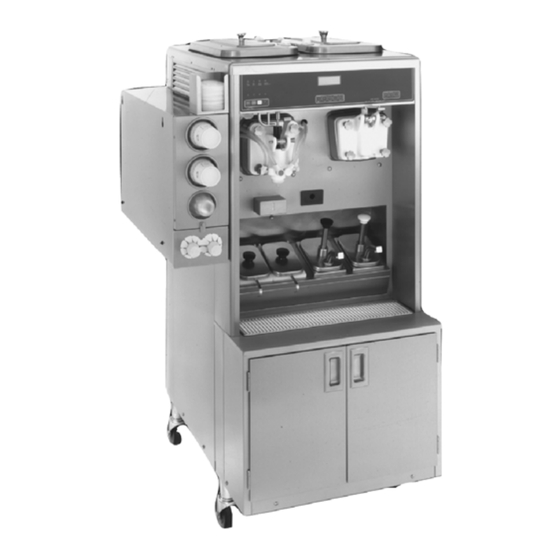
Soft Serve/Shake Combination Freezer
Taylor Model 8634-HT
Place this chapter in the
Shakes/Desserts section of the
Equipment Manual.
Manufactured exclusively for
McDonald's® by
Taylor Company
750 N. Blackhawk Blvd.
Rockton, IL 61072
Phone: (815) 624-8333
Toll Free Number
Outside Illinois:
1 (800) 228-8309
Inside Illinois:
1 (800) 851-5639
Fax: (815) 624-8000
Table of Contents
. . . . . . . . . . . . . . . . . . . . . . . . . . . . . . . . . . . . . . . . . . . . . . . . . . . . .
. . . . . . . . . . . . . . . . . . . . . . . . . . . . . . . . . . . . . . . . . . . . . . . . . . . . . . . . . .
. . . . . . . . . . . . . . . . . . . . . . . . . . . . . . . . . . . . . . . . . . . . . . . . . . . .
. . . . . . . . . . . . . . . . . . . . . . . . . . . . . . . . . . . . . . . . . . . . . . . . . . . . .
. . . . . . . . . . . . . . . . . . . . . . . . . . . . . . . . . . . . . . . . . . . . . . . .
. . . . . . . . . . . . . . . . . . . . . . . . . . . . . . . . . . . . . . . . . . . . . . . . . .
. . . . . . . . . . . . . . . . . . . . . . . . . . . . . . . . . . . . . . . . . . . . . . . . .
Warranty
A warranty checkout card is shipped with every new freezer that leaves the factory. The warranty checkout card is
packed in an envelope which also contains this operator's manual. Refer to the warranty checkout card and the warranty
classifications listed in the Parts Identification/Function section when service is performed on your freezer.
It is recommended that the operator take the necessary time to carefully read through the complete warranty information
contained in the warranty checkout card. Any questions or unclear statements found within the card should be made
clear to you upon delivery of the freezer. Thoroughly understand your warranty protection before you begin operation.
For any questions pertaining to the Taylor Warranty, please contact your authorized Taylor Distributor or Taylor
Company, Rockton, Illinois 61072.
This manual is for the exclusive use of licensees and employees of McDonald's Corporation.
E2004 McDonald's Corporation
All Rights Reserved
. . . . . . . . . . . . . . . . . . . . . . . . . . . . . . . . . . . . . .
. . . . . . . . . . . . . . . . . . . . . . . . . . . . . . . . . . . . . . . . .
. . . . . . . . . . . . . . . . . . . . . . . . . . . . . . . . . . . . . . . . .
. . . . . . . . . . . . . . . . . . . . . . . . . . . . . . . . . . . . . . . . .
. . . . . . . . . . . . . . . . . . . . . . . . . . . . . . . . . . . . . . . . . . .
. . . . . . . . . . . . . . . . . . . . . . . . . . . . . . . . . . . . . . . . . . . .
. . . . . . . . . . . . . . . . . . . . . . . . . . . . . . . . . . . . . .
. . . . . . . . . . . . . . . . . . . . . . . . . . . . . . . . . . . . . .
February, 2004 (Original Publication)
(Updated June, 2015)
EM SD11
Page 1
Page 1
Page 4
Page 28
Page 29
Page 31
Page 34
Page 38
Page 42
Page 47
Page 65
Page 69
Page 79
Page 81
Page 82
Printed in
The United States of America
Advertisement
Table of Contents

Related Manuals for Taylor 8634-HT


Summary of Contents for Taylor 8634-HT
-
Page 1: Table Of Contents
Any questions or unclear statements found within the card should be made clear to you upon delivery of the freezer. Thoroughly understand your warranty protection before you begin operation. For any questions pertaining to the Taylor Warranty, please contact your authorized Taylor Distributor or Taylor Company, Rockton, Illinois 61072. -
Page 3: Introduction
The 8634-HT is designed for indoor use only. the conductors from abrasion. 080910... - Page 4 If the supply cord is damaged, it must be replaced by an authorized Taylor WARNING! service technician in order to avoid a hazard. Some consumers are highly allergic to strawberries. In some severe cases, strawberry allergic This equipment is provided with a reactions can cause death.
- Page 5 HAZARD COMMUNICATION STANDARD (HCS) - The procedure(s) in this manual include the use of chemical products. If the crossed out wheeled bin symbol These chemical products will be is affixed to this product, it signifies that this highlighted with bold faced letters followed product is compliant with the EU Directive as by the abbreviation (HCS) in the text well as other similar legislation in effect after...
-
Page 6: Parts Identification/Functions
PARTS IDENTIFICATION/FUNCTIONS 8634 Exploded View (See Figure 1) ITEM PART NO. DESCRIPTION QTY. FUNCTION WARR. CLASS X65369 Kit A.-Cover-Hopper Protects mix in mix hopper from any *Single* debris. Helps keep temperature in mix hopper uniform. X44797 Agitator A.-Mix Hopper Stirs product in mix hopper to assure even temperature. - Page 7 8634 Exploded View (Cont'd.) ITEM PART NO. DESCRIPTION QTY. FUNCTION WARR. CLASS 051642 Pan-Drip 13-1/4 Long Used to catch any mix leakage from the rear shell bearing. Insulates syrup cabinet to keep an X45726 Door A.-Syrup Cabinet *Left even temperature. X45729 Door A.-Syrup Cabinet Insulates syrup cabinet to keep an...
- Page 8 Exploded View Figure 1 130809...
- Page 9 Front View (See Figure 2) ITEM PART NO. DESCRIPTION QTY. FUNCTION WARR. CLASS X35584SER2 Motor A.-Spinner Turns spinner shaft assembly. w/Plug 020108 Coupling-Flexible Connects spinner motor to w/Screws coupling assembly and provides adjustment for spinner shaft. 024295 Switch-Toggle DPDT Controls power to the machine. On-None-On X20329 Coupling A.-Drive-...
- Page 10 Front View (Cont'd.) ITEM PART NO. DESCRIPTION QTY. FUNCTION WARR. CLASS 068109 Overload-Thermal- Remote Pump Shake 068136 Insulator-Overload- Mix Pump Protects beater motor from 068038 Clip-Retainer-Overload overload. Pump Motor 067965 Overload-Thermal- Remote Pump Soft Serve 045533 Tank-Syrup 4 Qt. Stainless steel storage tank for (3.8 Liter) syrup.
- Page 11 Front View Figure 2 130809...
- Page 12 Side View Without Panels (See Figure 3) ITEM PART NO. DESCRIPTION QTY. FUNCTION WARR. CLASS 062191-1 Belt-Rd 3/16 Green Used to turn pulleys on agitator motor. 062191-2 Belt-Rd 3/16 Green Used to turn pulleys on agitator motor. 031324 Bearing-Rear Shell Aligns the drive shaft, and in conjunction with the drive shaft seal, prevents leakage of mix to...
- Page 13 Side View Without Panels Figure 3...
- Page 14 Rear View Without Panels ITEM PART NO. DESCRIPTION QTY. FUNCTION WARR. CLASS 024396 Belt-AX33 (Soft Serve) Used to turn pulleys. 052191 Belt-AX30 (Shake) Used to turn pulleys. 055813-2 Condenser-Main (A/C) Dissipates heat which has been Right (from front) removed from the mix. 055813-1 Condenser-Main (A/C) Dissipates heat which has been...
- Page 15 Mix Hopper - Top View ITEM PART NO. DESCRIPTION QTY. FUNCTION WARR. CLASS X44761 Sleeve A.-Mix Pump Hub used to hold the air/mix pump in a locked position. X41348 Probe A.-Mix Out Electrical device to indicate level of mix in the mix hopper. Activates the MIX OUT light on front of freezer.
- Page 16 O-Ring (Draw Valve Provides seal between spout cap Cap) and door spout. 017203 Cup-Divided Syrup Used for calibrating syrup. 048232 Lube-Taylor Hi Lubricant for moving parts and wear Performance items. X45080 Bottle-A.-Squeeze Used to clean and sanitize syrup ports in freezer door.
- Page 17 Accessories Figure 6...
- Page 18 Beater Door Assembly - Shake Side (See Figure 7) ITEM PART NO. DESCRIPTION QTY. FUNCTION WARR. CLASS 050985 Shaft-Beater 7 Qt. Connects beater assy. to gear unit. 041103 Blade-Scraper Scrapes frozen product off wall of freezing cylinder. 032560 Seal-Drive Shaft Provides seal from product inside freezing cylinder to internal areas of freezer.
- Page 19 Beater Door Assembly - Shake Side ITEM PART NO. DESCRIPTION QTY. FUNCTION WARR. CLASS 024278 O-Ring (Syrup Hole Prevents leakage at syrup hole Plug) plug. 053397 Fitting Syrup Valve Connects syrup line to freezer door. Figure 7 130814...
- Page 20 Beater Door Assembly - Soft Serve Side (See Figure 8) ITEM PART NO. DESCRIPTION QTY. FUNCTION WARR. CLASS 032560 Seal-Drive Shaft Provides seal from product inside freezing cylinder to internal areas of the freezer. 032564 Shaft-Beater Connects beater assy. to gear unit. X46231 Beater A.
- Page 21 Beater Door Assembly - Soft Serve Side Figure 8 130814...
- Page 22 Syrup Tank (See Figure 9) ITEM PART NO. DESCRIPTION QTY. FUNCTION WARR. CLASS 045533 Tank-Syrup (4 qt./3.8 liter) Stainless steel storage tank for syrup. 035759-1 Cover-Tank 8 Quart Locks into place to seal syrup tank. 1a-1 021077 Plug-Quick Disconnect Connection between the air line CO2 1/8 MP assembly and the syrup tank.
- Page 23 Syrup Tank Figure 9 130814...
- Page 24 Syrup Pump X53800-BRN/TAN (See Figure 10) ITEM PART NO. DESCRIPTION QTY. FUNCTION WARR. CLASS X53800-TAN Plunger A. Distributes and heats syrup X53800-BRN toppings. X36576-TAN Plunger A. Used to dispense toppings. X36576-BRN 032762-TAN Knob-Plunger Holds plunger assembly in place. 032762-BRN TAN and BRN indicate the hot caramel and hot fudge toppings.
- Page 25 Syrup Pump X53800-BRN/TAN Figure 10 130814...
- Page 26 X57028-XX Pump A. - Mix Simplified - Shake (See Figure 11) ITEM PART NO. DESCRIPTION QTY. FUNCTION WARR. CLASS 1 - 7 X57028-14 Pump A.-Mix Delivers air and mix to the Simplified Shake freezing cylinder. 057944 Cylinder-Pump- Chamber to house the piston. Hopper-Shake X55450 Pin-Retaining...
- Page 27 X57028-XX Pump A. - Mix Simplified - Shake Figure 11 130814...
- Page 28 X57029-XX Pump A. - Mix Simplified - Soft Serve (See Figure 12) ITEM PART NO. DESCRIPTION QTY. FUNCTION WARR. CLASS 1 - 7 X57029-14 Pump A.-Mix Delivers air and mix to freezing Simplified Soft Serve cylinder. 057943 Cylinder-Pump- Chamber to house the piston. Hopper-Soft Serve X55450 Pin A.-Retaining...
- Page 29 X57029-XX Pump A. - Mix Simplified - Soft Serve Figure 12 130814...
-
Page 30: Important To The Operator
To better communicate in the International arena, the words on many of our operator = MENU switches and buttons have symbols to indicate their functions. Your Taylor equipment is = MIX LOW designed with these International symbols. = MIX OUT The following chart identifies the symbol definitions. -
Page 31: Daily Opening Procedures
6. Fill the cup dispensers, cup lid holder, and DAILY OPENING PROCEDURES cone dispenser. To fill the cone dispenser, slide the drawer up and pull out. Push the Evaluate the condition of LED's (lights) and spring guide all the way back to its locking screen messages (Hard Lock or Soft Lock, position. - Page 32 4. With the syrup port brush, brush each 6. Install the restrictor cap on the freezer syrup port hole 10 to 15 times. Dip the door spout. (See Figure 18.) brush in sanitizing solution before brushing each port. (See Figure 16.) Figure 18 7.
-
Page 33: Syrup System
Soft Serve Side 6. When ready to resume normal operation, press the AUTO key. (See Figure 22.) 1. Prepare a small amount of KAY-5® Sanitizer (HCS) solution according to the manufacturer's specifications. Sanitize the design cap in this solution. 2. Return to the freezer with a small amount of sanitizing solution. - Page 34 Filling Syrup Tanks 4. Replace the tank lid, match and connect the spiral wrapped syrup line to the syrup 1. To fill the syrup tanks, pull back on the tank. Connect the air line to the syrup collar of the quick disconnect fitting for the tank.
- Page 35 2. Push the corresponding flavor button for 6. Hold the small portion of the calibrating that syrup flavor. (See Figure 29.) cup under the syrup line with the syrup sampler. Press the CAL key. Press the AUTO key to check the rate of syrup flow. After 5 seconds the flow of syrup will automatically stop.
-
Page 36: Daily Closing Procedures
4. If more than 1 fl. oz. (30 ml.) is received, Note: Whenever a particular syrup line is not used, the syrup hole plug found in the spare the pressure must be decreased. Loosen parts kit must be installed. Place the syrup the lock nut and turn the adjusting screw hole plug o-ring into the groove of the syrup COUNTERCLOCKWISE to zero. - Page 37 2. Remove the agitator from the mix hopper. 7. Remove the syrup lines from the freezer Remove the restrictor cap from the freezer door. door spout. Take the agitator, hopper 8. Return to the freezer with a small amount cover, shake cup holder, drip pans, front of cleaning solution.
- Page 38 10. Fill the squeeze bottle with cleaning 12. Install the syrup hole plugs in the syrup solution. With a pail beneath the door, ports in the freezer door. (See Figure 42.) insert the adapter end of the squeeze bottle into the syrup port, and squeeze the bottle firmly.
- Page 39 MAKE SURE YOUR HANDS ARE CLEAN AND 8. Remove, clean and reinstall the long drip SANITIZED BEFORE PERFORMING THESE pan through the front panel and the the NEXT STEPS. two short drip pans in the rear panel. (See Figure 45.) 3.
-
Page 40: Syrup Pump
There are 3 phases of the heat cycle: Heating, 4. To remove the knob, compress the spring toward the knob, using the washer. Holding and Cooling. Each phase has a time Compress it enough to grab onto the limit. If any one of the three phases fail to plunger with your hand for support. - Page 41 9. Remove the seal assembly from the 13. Remove the cylinder from the valve body. plunger assembly. (See Figure 51.) (See Figure 54.) Figure 51 Figure 54 10. Remove the seal o-ring from the seal. 14. Remove the discharge tube from the (See Figure 52.) valve body.
- Page 42 4. Insert the brush through the tip of the 8. Insert the brush, by the non-bristle end, discharge tube. Move the brush back and into the passageway between the inlet forth to scrub the tip of the discharge valve and the outlet valve. tube.
- Page 43 13. Sanitize the parts following your local 7. Install the plunger tube assembly onto the sanitization requirements. Allow the parts plunger assembly by inserting the plunger to air dry after sanitization. assembly into the larger opening on the plunger tube. Push the plunger assembly, compressing the spring, until the threaded Syrup Pump Assembly end of the stem projects through the...
-
Page 44: Manual Brush Cleaning
Turn FOLLOW YOUR LOCAL HEALTH CODES. the cylinder clockwise until the tabs fully engage into the locking grooves on the To disassemble the Model 8634-HT, the valve body. following items will be needed: Two cleaning and sanitizing pails for 13. - Page 45 Draining Product From The Freezing 6. When the flow of product stops, press the Cylinder WASH and PUMP keys and close the draw valve. Discard this product. To drain the product from the freezing cylinder (See Figure 71.) for both sides, the steps will be the same. Therefore, first drain the product from the shake side, then go back and duplicate these procedures for the soft serve side.
- Page 46 Note: Do not brush clean the mix inlet hole 5. Place an empty pail beneath the door while the machine is in the WASH mode. spout. 6. Open the draw valve on the freezer door 2. With a mix pail beneath the door spout, and draw off all the solution.
- Page 47 5. Remove the drive shaft seal from the 3. Remove the handscrews, freezer door, drive shaft. beater and scraper blades, and drive shaft with drive shaft seal from the 6. Remove the freezer door o-ring, front freezing cylinder. bearing, pivot pin, draw handle and draw valve spinner assembly.
- Page 48 11. Remove the long drip pan from the front Brush Cleaning panel and the two short drip pans from We recommend brush cleaning all the shake the rear panel. Take these items to the parts, then go back and duplicate these steps sink for cleaning.
-
Page 49: Equipment Set-Up
Note: When lubricating parts, use an 7. Prepare a sink with KAY-5® Sanitizer approved food grade lubricant (example: (HCS) solution according to the Taylor Lube HP). manufacturer's specifications. Repeat step 3 with sanitizing solution. 8. Rinse all parts in KAY-5® Sanitizer (HCS) solution for a minimum of 1 minute. - Page 50 3. Check scraper blades for any nicks or 6. Assemble the freezer door. Place the signs of wear. If any nicks are present, freezer door o-ring into the groove on the replace the blades. back of the freezer door. DO NOT lubricate the o-ring.
- Page 51 8. Assemble the draw valve spinner 11. Place an even coat of Taylor Lube Hi assembly. Inspect draw valve o-rings for Performance to the smaller end of the cuts or nicks. (Replace if cut or nicked.) If driven spinner. (See Figure 89.)
- Page 52 14. Install the draw valve spinner assembly. 17. Lubricate the shaft of the spinner blade up Insert the draw valve from the bottom until to the groove. (See Figure 95.) the slot in the draw valve which accepts the draw handle comes into view. (See Figure 92.) Figure 95 18.
- Page 53 With the parts tray available for the soft serve side: 1. Before installing the drive shaft, lubricate the groove on the drive shaft using Taylor Lube Hi Performance. Slide the drive shaft seal over the small end of the shaft and engage into the groove on the shaft.
- Page 54 2. Insert the drive shaft through the rear shell bearing in the freezing cylinder and engage the hex end firmly into the drive coupling. (See Figure 100.) Figure 102 Note: The hole on the scraper blade must fit securely over the pin to prevent costly damage.
- Page 55 8. Slide the beater assembly the rest of the criss-cross pattern to insure the door is way into the freezing cylinder. snug. (See Figure 107.) 9. Rotate and insert the beater assembly in position over the drive shaft. When properly seated over the drive shaft, the beater assembly will not protrude beyond the front of the freezing cylinder.
- Page 56 15. Insert the draw valve from the bottom until Note: The soft serve side features an adjustable draw handle to provide portion the slot in the draw valve comes into view. control, giving a better consistent quality to (See Figure 110.) your product and controlling costs.
- Page 57 20. Slide the two notched drip pans into the left and right side panels. (See Figure 115.) Figure 117 3. Apply a thin layer of lubricant to the inside Figure 115 of the pump cylinder at the retaining pin 21. Install the front drip tray and splash shield hole end.
- Page 58 5. Assemble the valve cap. Slide the red o-ring into the groove of the valve cap. DO NOT lubricate the o-ring. (See Figure 120.) Figure 123 The adapter must be positioned into the notch located at the end of the pump cylinder.
- Page 59 11. Install one red o-ring on each end of the 13. Slide the large black o-ring and the two mix feed tube, and thoroughly lubricate. smaller black o-rings into the grooves on (See Figure 126.) the drive shaft. Thoroughly lubricate the o-rings and shaft.
- Page 60 Sanitizing - Shake Side 1. Prepare 2.5 gallons (9.5 liters) of KAY-5® CAUTION! Sanitizer (HCS) solution. Use one packet Install the pump end of the mix feed in 2.5 gallons (9.5 liters) of water (100 tube and secure with the cotter pin. PPM).
- Page 61 14. Press the WASH and PUMP keys to stop Note: To assure sanitary conditions are maintained, brush clean each item for a the WASH and PUMP modes. Close the total of 60 seconds, repeatedly dipping draw valve. (See Figure 132.) the brush in sanitizing solution.
- Page 62 4. Install the pump assembly at the rear of the mix hopper. To position the pump on the drive hub, align the drive slot in the piston with the drive crank of the drive shaft. Secure the pump in place by slipping the pump clip over the collar of the pump, making sure the clip fits into the grooves in the collar.
- Page 63 Priming - Shake Side Note: Evaluate the condition of LED's (lights) and screen messages before performing priming procedures. If all 4 LED's are flashing, the unit is locked. 1. With a mix pail beneath the door spout, open the draw valve. Pour 2-1/2 gallons (9.5 liters) of FRESH mix into the mix hopper and allow it to flow into the freezing cylinder.
- Page 64 Operating Screen Descriptions POWER SWITCH OFF When the machine is powered the system will - = - = - = - = - = - initialize. The screen will display UNIT CLEANED “INITIALIZING”. There will be four types of data the system will check: LANGUAGE, SYSTEM DATA, CONFIG DATA, and LOCKOUT DATA.
- Page 65 The following displays pertain to the HEAT This example illustrates that the temperature cycle: is being lowered, but has not yet reached the set point. While in the heating phase, you will see this display. It shows the present temperature of the hopper.
- Page 66 The next display is the screen which will NO HEAT TREAT START appear after the failure message. To comply BECAUSE with health codes, heat treatment system VARIABLE MESSAGE freezers must complete a heat treatment PRESS SEL KEY cycle daily, and must also be brushed cleaned every 14 days.
-
Page 67: Operator Menu
If the WASH key is pressed, the next display Listed below are the variable messages which will appear and the freezer will have to be will appear, along with the corrective action: disassembled and brush cleaned. 1. NO FAULT FOUND: There was no fault found in the freezer. - Page 68 d. The barrel temperature has not fallen Press the SEL key to view the second screen below 41_F. (5_C.) by the end of the of the SYSTEM INFORMATION display. This COOL phase in the heat cycle. screen will indicate the Bill of Material number and serial number for the unit.
- Page 69 The SERVINGS COUNTER screen indicates 11/07 02:00 05:09 the number of times the draw switch has HEAT OVER COOL closed (number of draws) since the last brush 01:09 00:45 01:14 cleaning or since the last serving counter TEMP AT END 38.5 reset.
- Page 70 Screen “J” is the STANDBY MODE. To place Press the CAL (<--) key or the WASH (-->) key the left side of the freezer in the STANDBY to move the cursor in the desired direction. mode, move the cursor under the word “yes”. Pressing the MENU/SEL key will store the state Press the SEL key to execute the command that is underscored by the cursor, and proceed...
-
Page 81: Part Description
PARTS REPLACEMENT SCHEDULE PART EVERY EVERY ANNUALLY EVERY 4 DESCRIPTION 3 MONTHS 6 MONTHS YEARS Door A.-Shake & Soft Serve Scraper Blade-Shake Scraper Blade-Soft Serve Drive Shaft Seal Freezer Door O-Ring-Shake Freezer Door Gasket-Soft Serve Front Bearing Front Shoes Draw Valve O-Ring Spinner Shaft Seal-Shake Pivot Pin O-Ring Design Cap-Soft Serve... - Page 82 PART EVERY EVERY ANNUALLY EVERY 4 DESCRIPTION 3 MONTHS 6 MONTHS YEARS Door Spout Brush Inspect & Replace if Minimum Necessary Syrup Port Brush Inspect & Replace if Minimum Necessary...
-
Page 83: Ordering/Service Information
Taylor Distributor or the It should also be noted, that Taylor does not Taylor Factory. Be prepared to provide the warrant the refrigerant used in its equipment. Model/Serial Number of the unit in question. -
Page 84: Wiring Diagrams
WIRING DIAGRAM - 3 PH. 047984-33 Rev. 2/04... - Page 85 WIRING DIAGRAM - 3 PH. 047984-62 Rev. 2/04...
- Page 86 044202-M...
Need help?
Do you have a question about the 8634-HT and is the answer not in the manual?
Questions and answers