Advertisement
- 1 About These Instructions
- 2 Intended Use
- 3 Product Description
- 4 Initial start-up
-
5
Operation
- 5.1 Cooling mode
- 5.2 Heating mode (reverse cycle mode)
- 5.3 Circulated air mode
- 5.4 Automatic mode
- 5.5 ACC mode
- 5.6 Notes on using air conditioning systems
- 5.7 Switching air conditioning system on / off
- 5.8 Selecting the operating mode with the remote control
- 5.9 Dehumidify
- 5.10 Setting fan level
- 5.11 Set temperature unit
- 5.12 Set the room temperature
- 5.13 Set clock
- 5.14 Set timer
- 5.15 Reset
- 5.16 Resend
- 5.17 Set time format
- 6 Cleaning
- 7 Maintenance
- 8 Repair
- 9 Troubleshooting guide
- 10 Technical Data
- 11 Service Center
- 12 Safety Instructions
- 13 Documents / Resources
About These Instructions
Icons and meanings
| Icon | Meaning |
 | Warns about danger to people |
 | Certified expert |
 | Additional information for understanding or optimising workflows. |
 | Icon for an action. Something has to be done here. |
| (Fig. 3-1) | Reference to a graphic e. g. , Figure 3 - Number 1 |
Warnings
Warnings are used in these instructions to warn people about damage to people and property.
- Always read and observe warnings.
| Warning word | Meaning |
 | Danger to people. Non-observation can result in death or serious injuries. |
 | Danger to people. Non-observation can result in death or serious injuries. |
 | Danger to people. Non-observation can result in minor to moderate injuries. |
| NOTICE | Information on preventing damage to property. |
Intended Use
The Saphir air conditioning system is designed for space-saving installation in a recreational vehicle (RV), for example in a cabinet or storage bench. The Saphir is designed solely for cooling and heating in living areas. The air conditioning system cools or heats the interior area quietly, efficiently and quickly to the set temperature It can be controlled using:
- Saphir remote control
- Truma CP plus (referred to below as CP plus)
- Truma CP plus VarioHeat (referred to below as CP plus VarioHeat)
- Truma CP plus CI bus
- Truma CP plus VarioHeat CI bus
- A third-party control panel via the RV-C bus
Use of air conditioning at an altitude of max 9800 ft (3000 m) above sea level.
Defective, improperly installed units or those units used, or units used contrary to the recommended use should not be used.
This product can expose you to chemicals including chloroform, methyl chloride, chloroethane (ethyl chloride), and vinyl chloride, that are considered to be causes of cancer and birth defects by the state of California For more information, go to P65Warnings.ca.gov
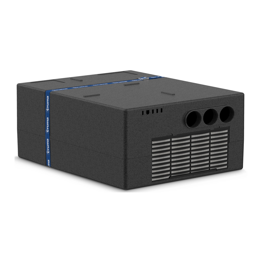
Product Description
The Saphir air conditioning system is designed for space-saving installation in a cabinet or storage bench (Fig 1).

Fig. 1
Hazard from air conditioning system becoming loose
In the event of an accident, an air conditioning system that is not fastened adequately can become loose. This can be a hazard.
- Ensure that the clamping strap (Fig 2-1) is fastened by pulling the strap taut and securing the buckle before moving the vehicle.

Fig 2

Supply air inlet and outlet
Supply air is drawn in and blown out through the vehicle's floor Holes are provided in the vehicle's floor for this purpose: air inlet (Fig 3-1) and air outlet (Fig 3-2).

Fig 3
Circulated air intake
The room air to be cooled is drawn in via the air inlet on the front of the Saphir (Fig 4), or an additional flexible air conditioning intake extends into the vehicle interior (also see "Clean/change air filter with installed flexible air conditioning intake (optional)").

Fig 4
Circulated air outlets
The cooled air is distributed in the vehicle interior through the front-mounted ducting (Fig 5).

Fig 5
Condensation trap
Condensation is drained via the vehicle's floor. Holes are provided in the vehicle's floor (condensation traps, see Fig 6-1) for this purpose, and the condensation will drain through them.
When the air conditioning system is operated for an extended amount of time, pools of water can form under the vehicle.

Fig 6
NOTICE
If the condensation traps are dirty, water can enter the interior The function of the air conditioning system will be adversely affected, which may result in damage. See "Clean condensation trap".
Product labeling
Air conditioning system type plate
The type plate is attached on the top of the air conditioning system (Fig 7-1).

Fig 7
A second type plate (duplicate) may be found in the operating instructions or at an easy-to-access point in the vehicle (depends on the vehicle manufacturer).
Remote control type plate
The type plate with the remote control's data is on the inside of the battery cover (Fig 8).
- Part number
- Hardware status (HW)
- Software status (SW)
- Production date

Fig 8

Air distribution in the interior
Circulated air outlets can be found in the lower parts (Fig 9) or, for better cooling performance, in the upper section of furniture walls (Fig 10)

Saphir remote control (optional)
The air conditioning system can be controlled with an IR remote control.
The remote control switches off automatically after about one minute to save the battery.
NOTICE
Heat can damage the remote control
- Do not leave the remote control in direct sunlight or on sources of heat.
Remote control signals are sent with infrared waves to the wall-mounted IR receiver (Fig 11).
")
Fig 11
There is an IR transmitter diode for this at the top of the remote control.
- To operate the air conditioning system, point the remote control at the IR receiver.
NOTICE
Do not cover the IR receiver.
The IR receiver must be exposed for fault-free operation.
- Do not place anything over the IR receiver.
- Do not cover the IR receiver (e.g. with curtains).
Button panels
The remote control has two button panels.
The buttons for the most important functions are on the top button panel. They are always visible.
The buttons for advanced functions are on the bottom button panel. This can be concealed with a cover.
- Push the cover down (Fig 12-1).
Bottom button panel is visible. - Push the cover up (Fig 12-2).
Bottom button panel is concealed.

Fig 12

Top button panel
The top button panel includes the following functions (Fig 13):

Fig 13
| Symbol | Description |
 | MODE Select operating modes
|
 | FAN Set fan operating level
|
 | ON/OFF |
 | TEMP + TEMP - Set temperature
|
Bottom button panel
The bottom button panel includes the following functions (Fig 14):

Fig 14
Symbols Description


Display
The remote control has an LCD (Fig 15) that shows the current settings. The display does not have background lighting.

Fig 15
Symbols Description


IR receiver (optional)
The IR receiver (Fig. 16) has the following display and control panels:

Fig 16
- Green LED
- Infrared sensor
- ON/OFF button
- Red LED
The additional push button on the IR receiver (Fig 16-3), with which the device can also be switched on and off without the remote control (e.g. with a ballpoint pen). When the unit is switched on, it will return to its previous settings.
| LED display | Description |
| Green LED flashes | IR receiver receives signals from the remote control |
| Red LED lights | Malfunction[1] |
[1] See: "Troubleshooting guide".
Holder for remote control (optional)
There is a holder for the remote control that can be mounted on a wall or cabinet in the vehicle (Fig 17).

Fig 17
- Place the remote control into the holder or remove it from above (Fig 18).
![]()
Fig 18

Accessories
There are various accessories for the air conditioning system. These may be installed with the air conditioning system, depending on the vehicle manufacturer.
Wall-mounted IR receiver
The remote control signals will be received by an IR receiver (Fig 19).
The vehicle manufacturer installs the IR receiver on an inside wall or cabinet.

Fig 19
Truma CP plus
The air conditioning system can be controlled with the CP plus digital control panel (available as an option).
The CP plus control panel has an automatic climate control function (ACC for primary heater), referred to as AUTO mode in the CP plus menu. This automatically controls the room temperature together with the Truma Saphir air conditioning system and a Truma Combi / Truma VarioHeat heater In AUTO mode, the air conditioning system will not be operated in reverse cycle mode (heating).
A Truma Combi / Truma VarioHeat or Alde heater must be installed to use the automatic climate control function on the Truma CP plus.

Fig 20
The vehicle manufacturer installs the CP plus (Fig 20) on an inside wall, cabinet or storage compartment It can be visible or hidden.
Operation
- See separate CP plus control panel operating instructions.
Initial start-up
The following section describes the initial start-up with Saphir remote control. For CP plus or third- party control unit, please refer to the operating instructions of the corresponding control unit.
- Before switching on, ensure that the vehicle is supplied with 120 V AC / 60 Hz protected with an 20 A circuit breaker.
The remote control must always be pointed at the infrared receiver in order to perform the individual switching commands.
Before switching on for the first time, the remote control must be paired with the IR receiver.
- Insert batteries (pay attention to polarity).
- Setup symbol flashes (if symbol does not flash, perform reset).
- Point the remote control at at the IR receiver.
- Press the setup button and hold down.
- When the green LED in IR receiver flashes, release the button to pair the remote control with the IR receiver.
The setup symbol goes off and the air conditioning system starts the circulated air mode at low fan level and with no timer set.
Operation
Cooling mode
The air conditioning system ensures cool air inside the vehicle when operated in cooling mode. The circulated air fan continues to run in order to provide ventilation.
The air is dehumidified during cooling If the air humidity in the vehicle is extremely high at the beginning of the cooling procedure, moisture can build up on the outside of the air ducts. The doors and windows should therefore be kept closed and the highest fan level selected.
Heating mode (reverse cycle mode)
Heating mode is used when a room temperature above outside temperature is desired. Saphir heats up the room air using reverse cycle mode. The circulated air fan continues to run in order to provide ventilation If the room temperature drops below the temperature setting, the compressor will automatically start.
Heating at an outside temperature of less than 39°F (4°C) is not recommended because heating performance falls considerably. Between 39°F (4°C) and 45°F (7°C), the device operates at the "low" fan level and switches briefly to defrosting processes (for several minutes). At above 45°F (7°C), there are no restrictions on heating mode. As soon as 54°F (12°C) is reached, the air conditioning system automatically switches to the fan setting selected on the remote control.
In order to achieve interior heating that is as effective as possible at low temperatures, the air conditioning system operates at the "low" level at room temperatures of less than 54°F (12°C). As soon as 54°F (12°C) is reached, the air conditioning system automatically switches to the fan setting selected on the remote control.
Circulated air mode
Circulated air mode only circulates the indoor air without heating or cooling it.
Automatic mode
The automatic mode automatically controls the room temperature by automatically switching between cooling and heating mode. Automatic mode is used when the room temperature can be above or below outside temperature during operation.
ACC mode
The ACC mode automatically controls the room temperature together with the Truma Saphir air conditioning system and a Truma Combi / Truma VarioHeat heater. It is referred to as AUTO mode in the CP plus menu In AUTO mode, the air conditioning system will not be operated in reverse cycle mode (heating).
Notes on using air conditioning systems
- To prevent damage to the device, it should not be operated continuously at an incline or decline of more than 8% (4,5°) in all directions.
- Do not operate the device for long periods with the vehicle at an angle, since the condensation that is produced may not be able to run off and may penetrate the vehicle under unfavourable circumstances.
- The Saphir air conditioning system is configured for current consumption up to 20 A.
- Before switching on, ensure that the vehicle is supplied with 120 V AC / 60 Hz protected with an 20 A circuit breaker
- Park the vehicle in the shade if possible.
- Darkening windows, doors or windshield with shutters or blinds reduces the amount of heat radiation.
- The vehicle should be properly ventilated before starting the equipment in order to remove accumulated warm air from the vehicle.
- When RV skirts or the like are being fitted, please ensure that adequate openings are present for dissipating the supply air. The opening for the warm outgoing air should not be at the inlet side.
- In order to obtain a comfortable room climate, the difference between the inside and outside temperatures should not be too great. The circulated air is cleaned and dried during operation. A pleasant room climate is produced by drying the moist air, even if the temperature difference is minimal.
- Keep all doors and windows closed when in cooling mode If doors or windows are open, condensation could build up on the ducts and cause moisture damage.
- When in the heating mode, use the "high" fan level only for rapid heating. Set to "medium" or "low" during continuous operation.
In order to achieve interior heating that is as effective as possible at low temperatures, the air conditioning system operates at the "low" fan level at ambient room temperatures of less than 54°F (12°C)
Operation with generator or power inverter
The air conditioner can be operated with a power inverter or generator The following specifications are recommended:
- Power inverter type: Pure sine-wave voltage
- Nominal voltage: 110 V - 130 V AC
- Phase: 1
- Frequency: 60 Hz +/- 5 %
- Inrush current capability: 150 ms with 115 V / 40 A RMS
- Loads: ohmic and inductive
- Recommended power: min 2000 W
Truma does not define the size of the generator in recreational vehicles When sizing the generator, the total power consumption of your RV must be considered Generators will lose power at high altitudes and if they are not maintained regularly
NOTICE
The wrong power supply can cause damage to and malfunctions in the air conditioner.
- With regard to the power supply, use only sources with a pure sine wave (e.g. voltage transformer, generator) and without voltage spikes
Switching air conditioning system on / off
Switch air conditioning system on (remote control)
- Press the ON/OFF button of the remote control The system's previous operating settings are overwritten and the device shuts down
The circulated air fan runs after switching on The compressor switches itself on after no more than 3 minutes
Switch air conditioning system off (remote control)
- Press the ON/OFF button on the remote control The remote control and the device are switched off
Switch air conditioning system on (push button)
- Press the ON/OFF button on the IR receiver (Fig 16-3) for one second, e.g. with a pen.
The green LED on the IR receiver flashes briefly.
The air conditioning system is switched on The air conditioning system starts with the following settings: Cooling mode, fan: low, temperature: 72°F (22°C)
Switch air conditioning system off (push button)
- Press the ON/OFF button on the IR receiver (Fig 16) for one second, e.g. with a pen.
The green LED on the IR receiver flashes briefly.
The air conditioning system is switched off.
Selecting the operating mode with the remote control
Select the required operating mode by pressing the "MODE" button one or more times.
- Press the MODE
![]() button one or more times. The desired operating mode is shown on the display with the corresponding icons.
button one or more times. The desired operating mode is shown on the display with the corresponding icons.
The green LED on the IR receiver flashes briefly.
The desired operating mode is set.
| Symbol | Description |
 | Cooling mode |
 | Dehumidify mode |
 | Heating mode |
 | Automatic mode |
 | Circulated air mode |
When the room temperature that was selected using the remote control is reached in cooling mode, the compressor switches off. The circulated air fan continues to run in order to provide ventilation If the room temperature setting is exceeded, the device automatically reverts to cooling mode.
An internal air temperature sensor prevents the compressor from operating at temperatures of less than 61°F (16°C) during cooling.
When the room temperature that was selected using the remote control is reached in heating mode, the compressor switches off. The circulated air fan continues to run in order to provide ventilation. If the temperature drops below the selected room temperature, the device automatically switches to heating mode.
In automatic mode the fan level is selected automatically depending on the difference between selected and actual room temperature.
Dehumidify
Dehumidify mode reduces humidity in the room. This mode must be switched on and off manually and is not controlled by room humidity level. The selected fan level setting (low, medium, high) is deactivated and the cooling mode activated.
- Press the DEHUMIDIFY
![]() button.
button.
The cooling mode![]() and dehumidify
and dehumidify ![]() icons are shown on the display.
icons are shown on the display.
The green LED on the IR receiver flashes briefly.
The air conditioning system dehumidifies the room.
 button.
 and dehumidify
 Press the button again to switch dehumidify mode off. The air conditioning system is then operated with the previous settings.
Setting fan level
The integrated air fan has three operating levels.
| Symbol | Description |
 | Operating level: low |
 | Operating level: medium |
 | Operating level: high |
- Press the FAN
![]() button for the desired operating level one or more times.
button for the desired operating level one or more times.
The fan's desired operating level is shown on the display.
The green LED on the IR receiver flashes briefly.
The desired operating level is set.

In the automatic mode, the FAN ![]() button has no function.
button has no function.
Set temperature unit
The temperature on the display can be shown in degrees Fahrenheit (°F) or Celsius (°C).
- Press the TEMP
![]() and TEMP
and TEMP ![]() buttons at the same time.
buttons at the same time.
The temperature display changes between °F and °C.
Set the room temperature
Use the "set temperature" buttons to set the required room temperature with "+" and "–".
The room temperature can be set in a range from 61°F (16°C) to 88°F (31°C) in steps of one degree.
- Set the room temperature with the temperature selection buttons, TEMP
![]() and TEMP
and TEMP ![]() .
.
The desired room temperature is shown on the display.
The green LED on the IR receiver flashes briefly.
The desired room temperature is set.
Set clock
After replacing the battery, when changing to or from daylight saving time, or when changing to a different time zone, you have to set the time manually If a timer is active, the clock cannot be changed.
- Press the TIME
![]() button.
button.
The time is shown flashing on the display. - Set the current hour with the HOURS
![]() and HOURS
and HOURS ![]() buttons.
buttons.
Set the current minute with the MIN![]() and MIN
and MIN ![]() buttons.
buttons. - Press the TIME
![]() button again or wait approx 10 seconds.
button again or wait approx 10 seconds.
The time is shown on the display.
The time is set.
 and HOURS
  buttons.
 The clock shows 12:00 pm at noon At midnight it shows 12:00 am.
Set timer
Two timers can be programmed.
- Timer ON.
The air conditioning system is off.
The time set in the timer determines when the air conditioning system is switched on. - Timer OFF.
The air conditioning system is on.
The time set in the timer determines when the air conditioning system is switched off.
The timer can be set in a range of minimum 15 minutes to maximum 24 hours. Times set in the timer of less than 15 minutes are rounded up to 15 minutes.
Only one timer can be active at one time.
If a timer is active, all buttons except ON/OFF ![]() , RESEND
, RESEND ![]() , TIMER
, TIMER ![]() and TIMER
and TIMER ![]() have no function.
have no function.
Times set in the timer are only sent to the air conditioning system when the TIMER ![]() or TIMER
or TIMER ![]() buttons have been pressed.
buttons have been pressed.
If the remote control goes to stand-by mode after approx one minute and a timer is active, then, next to the current time, the timer set time is shown on the display with the corresponding timer ON or timer OFF icons.
When the timer has been programmed, no further communication between the remote control and the IR receiver is required for the timer function to operate. After programming, the remote control can be placed in the holder or a drawer.
Program timer ON
- Switch the air conditioning system on with the remote control.
The air conditioning system runs with the previously selected settings. - Set the desired operating mode and room temperature.
- Press the TIMER
![]() button.
button.
The timer ON icon is shown on the display.
The timer flashes. - Set the timer set time with the HOURS
![]() and HOURS
and HOURS ![]() buttons.
buttons.
Set the minutes with the MIN![]() and MIN
and MIN ![]() buttons.
buttons. - Confirm the setting with the TIMER
![]() button.
button.
The time set in the timer is shown on the display with the ON icon. The time set in the timer is sent to the air conditioning system. The gr.een LED on the IR receiver flashes briefly. The air conditioning system switches off and the timer starts. - Wait approx one minute while the remote control goes to stand by. If the ON/OFF
![]() button is pressed after timer programming, the air conditioning system switches on again and the time set in the timer is deleted.
button is pressed after timer programming, the air conditioning system switches on again and the time set in the timer is deleted.
 and HOURS
  and MIN
  buttons.
 button.
When the time set for timer ON is reached, the air conditioning system starts automatically with the previously selected settings.
Program timer OFF
- Switch the air conditioning system on with the remote control.
The air conditioning system runs with the previously selected settings. - Set the desired operating mode and room temperature.
- Press the TIMER
![]() button.
button.
The timer OFF icon is shown on the display.
The timer flashes. - Set the timer set time with the HOURS
![]() and HOURS
and HOURS ![]() buttons.
buttons.
Set the minutes with the MIN![]() and MIN
and MIN ![]() buttons.
buttons. - Confirm the setting with the TIMER
![]() button.
button.
The timer is shown on the display with the OFF icon.
The time set in the timer is sent to the air conditioning system.
The green LED on the IR receiver flashes briefly.
The air conditioning system runs with the previous settings and the timer starts. - Wait approx one minute while the remote control goes to standby. If the ON/OFF
![]() button is pressed after the timer programming, the air conditioning system switches off again and the time set in the timer is deleted.
button is pressed after the timer programming, the air conditioning system switches off again and the time set in the timer is deleted.
 button.
When the time set for timer OFF is reached, the air conditioning system switches off automatically.
Switch timer off
- Press the TIMER
![]() or TIMER
or TIMER ![]() button again.
button again.
No timer is shown on the display.
The green LED on the IR receiver flashes briefly.
The timer is switched off.
Reset
The remote control settings can be reset to the factory settings with the reset button.
- Press the RESET button
![]() for 3 seconds, with a pen, for example.
for 3 seconds, with a pen, for example.
All icons flash briefly on the display. The remote control switches off and the air conditioning system continues to run unchanged. The next time the remote control is activated, the default factory settings are set.
Factory settings:
- Operating mode: Circulated air
- Fan: Low
- Time: 12:00 pm
- Timer: Off
- Temperature: 72°F (22°C)
Resend
Sending settings to the air conditioning system can fail if, for example, the remote control was not pointed precisely at the IR receiver In this case, the previously selected settings can be sent again.
- Press the RESEND
![]() button.
button.
The send icon![]() is shown briefly on the display.
is shown briefly on the display.
The green LED on the IR receiver flashes briefly.
Settings are sent.
 button.
 is shown briefly on the display.
Set time format
The time on the display can be shown in the 12 or 24-hour format.
- Press the TIMER
![]() and TIMER
and TIMER ![]() buttons at the same time.
buttons at the same time.
The time format changes between AM / PM and 24-hour format.
If a timer is activated, the timer must be switched off via the remote control and programmed again.
Cleaning
NOTICE
Damage to the device caused by water ingress through openings in vehicle underbody
- When cleaning the vehicle floor with a high-pressure water blaster, avoid the area around the supply air inlet and outlet.
- Do not use any abrasive cleaning agents or sharp objects. Use a soft, damp cloth to clean the air conditioning system.
- Do not use gasoline, diesel, solvent, chemical cleaning agents, alcohol, surfactants or plasticisers for cleaning.
Clean supply air inlet and outlet
- Keep the air conditioning system's air inlets and air outlets in the vehicle floor free of obstructions, e.g. dirt or foliage, to ensure optimum performance and optimum air flow rate. Otherwise, the function of the air conditioning system will be adversely affected, which may result in damage.
NOTICE
Water in the air conditioning system can cause damage and malfunctions.
- Do not clean the air conditioning system with a hot/steam cleaner or high-pressure cleaner.
- If cleaning the vehicle with a hot/steam cleaner or high-pressure cleaner, do not spray directly into the air conditioning system's openings.
- When the vehicle underbody is being cleaned, it must be ensured that no water penetrates the openings in the base of the device. Do not point a high-pressure water jet, for example, directly into the openings.
Clean condensation trap
The condensation trap is under the vehicle floor In order to allow the condensation to drain away freely, check unobstructed trap at regular intervals. Failure to do this may allow condensation to penetrate the vehicle.
- Keep the air conditioning system's condensation traps in the floor free of obstructions, e.g. dirt or foliage.
- Keep the internal condensation trap clean.
Clean/change air filter with installed flexible air conditioning intake (optional)
With a built-in flexible air conditioning system intake, the air filter is located in the end frame of the intake (Fig 21-1), not in the Saphir housing.

Fig. 21
- To change the air filter, slide the Saphir US lamellar insert and air filter in an upwards direction to release.
- Re-fit the air filter and Saphir US lamellar insert from the top (Fig 21-2) and (Fig 21-3).
Maintenance
Change air filter
There is an air filter on the front of the device for cleaning the room air. The air filter (Fig 24-1) must be checked at regular intervals (at least 2 x per year) and changed if required.
- Remove the cold air ducts.
- Before replacing the air filter, release the clip (Fig 22-2) and the sensor (Fig 22-1) located on the Saphir US lamellar insert using a flat-bladed screwdriver.

Fig. 22 - Pull the Saphir US lamellar insert a little way forward at the recesses at the top edge (Fig 23-1) and pull out upwards (Fig 23-2).

Fig 23 - Then remove air filter from the front.
- Reassemble the cleaned or changed air filter (Fig 24-1) Make sure that the air filter is correctly aligned, as indicated by the arrow printed on it (Fig 24-3).
- Re-fit the Saphir US lamellar insert (Fig 24-1), clip and sensor in the same position during assembly.
- Re-fit the cold air ducts.

Fig 24


NOTICE
Operating the device without a filter can cause evaporator coil soiling, which can have a detrimental effect on the performance of the device!
- When installing the air filter, the printed arrows (Fig 24-3) must point towards the device – they indicate the circulated air flow direction.
- Never operate the device without a filter.
Insert/change batteries
The battery cover is on the rear of the remote control (Fig 25)
When removing the batteries, pairing between the remote control and the air conditioning system is maintained. The time and timer are not maintained.
- Only use leakproof micro-batteries, type LR 3, AM4, AAA, MN 2400 (15 V).
- Observe the positive/negative positions when inserting new batteries.
- Then set the time and timer again.

Fig 25

Low used batteries can leak and damage the remote control.
- Remove batteries when the remote control will not be used for longer periods.
Repair
There are no user serviceable parts inside the Saphir housing. Do not attempt to open the housing In the event of a malfunction, refer to "Troubleshooting guide" or contact Truma Corp service.

Electric shock from electric power on charged capacitors
The air conditioning system contains live parts (e.g. capacitor), which may still hold life-threatening residual voltage even after the system has been switched off.
- Before disposing of or replacing capacitors, have them discharged by an expert.

Only experts should discharge capacitors.

Burns from hot parts
Parts that can get hot during operation are installed in the air conditioning system.
- Do not open the air conditioning system.
- Do not mount the air conditioning system at other places and do not install it in other vehicles.
- Do not dismantle the air conditioning system, convert it or repair it yourself.
- Only have installation, dismantling or repair work done by trained experts.
Injuries are caused by moving parts
Hand injuries caused by touching the rotating air fan inside the housing
- Do not open the air conditioning system.
Troubleshooting guide
Is the vehicle 120 V AC power cord properly connected, and are the fuses and circuit breakers blown or tripped?
| Fault | Cause / Remedy |
| Device not cooling | Defrost process in progress / wait until thawing procedure is complete. The temperature set on the remote control has been reached / set temperature on remote control to less than room temperature. |
| Device not heating | Defrost process in progress (outside temperature between 39°F - 45°F (4°C – 7°C)) / adjust fan to lower setting. Outside temperature below 39°F (4°C). |
| Device providing insufficient cooling or no cooling at all | Filter soiled / change filters. External air routes soiled, blocked / clear air routes. |
| Moisture at cold air ducts | High air humidity / close windows and doors and select high fan level. |
| Remote control not working | Check batteries in remote control / replace batteries if necessary. |
| Device not reacting to remote control commands | Check whether there are obstructions between the remote control and the IR receiver / remove obstructions if necessary. Is the remote control paired with the IR receiver? |
If these actions fail to remedy the fault, please contact Truma Service.
Technical Data
Established in line with AHRI Standard 210/240
| Designation | Saphir |
| Cooling capacity equivalent | 7000 BTU / h |
| Heating capacity equivalent | 6500 BTU / h |
| Electrical rating | 120 VAC, 60 Hz ± 5% single phase |
| Compressor Rated Load | 6.5 A |
| Compressor Locked Rotor | 38 A |
| Fan Motor Rated Load | 1.1 / 1.16 A (indoor / outdoor) |
| Fan Motor Locked Rotor | 0,18 / 019 HP (indoor / outdoor) |
| Refrigerant | R-410A 16.9 oz (480 g) |
| Minimum wire Size1 copper | 3 x AWG 12 / 3 x 3.3 mm2 |
| AC Circuit protection installer supplied2 | 20 Amp |
| Limits of use | 39 – 113°F (4°C – 45°C) |
| Max air conditioner incline in operation | 8% (4.5°) |
| Weight, plus installation material | 54.5 lbs (24.7 kg) |
| Adjustable temperature range | 62 - 88°F 16 - 31°C |
| Protection type | IPX5 |
| Generator size3 | |
1 For wire length over 24 ft, consult the National Electrical Code for proper sizing
2 Circuit Protection: Time delay fuse or circuit breaker required
3 See "Operation with generator or power inverter".
An interior air sensor prevents the compressor from operating at temperatures of less than 61°F (16°C) during cooling.
An anti-freeze sensor prevents non-permitted ice formation on the evaporator coil.
A temperature switch prevents excessive current and temperature at the compressor.
Truma Gerätetechnik reserves the right to make technical changes!
Dimensions

Fig. 26 (see table below)
| Dimension | Length in. | Length mm |
| a | 25 13/16 | 656 |
| b | 20 1/2 | 520 |
| c | 12 3/8 | 314 |
Stickers
The following stickers (Fig. 27), (Fig.28) are provided inside the air conditioning system:

Fig. 27

Fig. 28 Saphir connection plan sticker
The following stickers (Fig. 29), (Fig.30) are provided on the outside of the air conditioning system:

Fig. 29

Fig. 30
Service Center
Truma Corp Service Center, 2800 Harman Drive, Elkhart, IN 46514,
toll free: (855) 558-7862,
fax. (574) 538-2426,
service@trumacorp.com
www.truma.net
All warranty claims must be reported to this Truma's authorized warranty service center in North America.
Safety Instructions
Installation, dismantling, conversion

Only qualified and trained persons (experts) may install, repair and perform the functional testing of the Truma product in compliance with the installation and operating instructions and generally approved engineering practises. Experts are people who, on the basis of their professional training and qualifications, their knowledge of and experiences with the Truma products and the applicable standards, perform the required work correctly and can identify possible dangers.
The following applies for non-experts:
- Do not open the air conditioning system.
- Do not mount the air conditioning system at other places and do not install it in other vehicles.
- Do not dismantle the air conditioning system, convert it or repair it yourself.
- Only have installation, dismantling or conversion work done by trained experts.
General safety
Failure to follow the provisions in the operating instructions can result in serious damage to property and gravely endanger people's health or life.
- To avoid transportation damage, the device may only be dispatched if the Truma Corp Service Centre or the respective authorised service partner has been consulted beforehand.
- Do not attempt to open the housing. There are no user servicable parts inside the Saphir housing.
- The device fuses and connector cables must only be replaced by experts.
- Guarantee claims, warranty claims and acceptance of liability will be ruled out in the event of the following:
- Modifications to the device (including accessories)
- Failure to use original Truma parts as spare parts and accessories
- Failure to follow the installation and operating instructions
- This may also invalidate the device's operating permit, which in many countries also denotes cancellation of the vehicle operating permit.
- The refrigerant circuit contains R 410 A refrigerant and must only be opened by experts.
- The air outlet and the circulated air intake must not be obstructed under any circumstances. This is essential in order to ensure that your device operates correctly.
- Do not touch the supply air intake and outlet on the bottom side of the air conditioning system during operation.
- The openings beneath the vehicle floor must be kept free of dirt, debris, and other obstructions. These openings must not be within the range of the wheel spray – fit splash guard if necessary.
- If underbody protection is being applied to the vehicle floor, all openings beneath the vehicle must be covered so that the spray mist that is created does not penetrate the device and cause malfunctions. Remove covers again when the work is complete.
- When the vehicle underbody is being cleaned, it must be ensured that no water penetrates the openings in the base of the device. Do not point a high-pressure water jet, for example, directly into the openings.
- This appliance is not intended for use by persons (including children) with reduced physical, sensory or mental capabilities, or lack of experience and knowledge, unless they have been given supervision or instruction concerning use of the appliance by a person responsible for their safety. Children should be supervised to ensure that they do not play with the appliance.
- The interior of the vehicle where persons in need of protection are located is cooled down considerably. Depending on the physical condition of the persons concerned, slight to severe damage to health could occur due to hypothermia.
Operator / vehicle owner's obligations
Safety with an approved power supply
- For fault free operation and to prevent electronic damage, only use a power supply with a pure sine wave (no voltage spikes) e.g. voltage transformers, generators and inverters.
Safe operation

Electric shock from bare, damaged power cable.
- With damage on a power cable, switch the power supply off, e.g. via fuses or Cut-off switch on the vehicle's main power distribution board. Disconnect power supply Secure against switching on again.
- Have the damaged wiring replaced by the manufacturer or a qualified expert.
Handling faults
- Have faults repaired immediately by an expert.
- Only rectify faults yourself if their rectification is described in section "Troubleshooting guide".
What to do with unusual sounds and smells
- Switch the air conditioning system off.
- Have the air conditioning system checked by an expert.
Documents / Resources
References

Download manual
Here you can download full pdf version of manual, it may contain additional safety instructions, warranty information, FCC rules, etc.
Advertisement


Need help?
Do you have a question about the Saphir and is the answer not in the manual?
Questions and answers