
Subscribe to Our Youtube Channel
Related Manuals for Truma Saphir comfort RC AU


Summary of Contents for Truma Saphir comfort RC AU
- Page 1 Saphir comfort RC AU Operating instructions Page 2 Installation instructions Page 9 To be kept in the vehicle!
-
Page 2: Table Of Contents
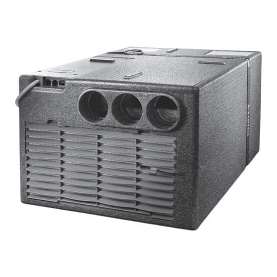
Saphir comfort RC AU Fig. 2 Installation example 1 Saphir comfort RC AU 2a Supply air intake 2b Supply air outlet 3a Circulated air intake 3b Air outlets 4 Infrared (IR) remote control 5 Infrared (IR) receiver Fig. 1 Table of contents Symbols used .............. -
Page 3: Safety Instructions
The device fuses and connection cables must Notes on using air conditioning systems only be replaced by experts. – The Saphir comfort RC AU is designed for Guarantee claims, warranty claims and ac- minimal power consumption. You should still ceptance of liability will be ruled out in the... -
Page 4: Operating Instructions
Operating instructions Always observe the operating instructions and the “Safety instructions” prior to starting! The vehicle owner is responsible for correct operation of the appliance. Remote control The symbols in the display are visible depending on the settings. Setup Resend / data transmission Sleep function Cooling... -
Page 5: Ir Receiver And Manual On / Off
Device indicating fault. Switch device off, wait for a short time the device briefly switches to thawing operation. Heating and switch on again. If red light stays on, contact Truma Service. mode is unrestrictedly available at temperatures above 7 °C. -
Page 6: Timer On / Off
The time always appears on the display. The time must be reset after changing the batteries or after a daylight saving time change. Timer ON / OFF The On / Off time of the air conditioning system can be set in advance for a minimum of 15 minutes to a maximum of 24 hours, starting from the current time, using the integrated timer... -
Page 7: Ir Remote Control Battery Change
Technical data IR remote control battery change Only use micro-batteries that will not leak, type LR 3, AM4, Determined on the basis of EN 14511 or Truma test conditions AAA, MN 2400 (1.5 V). Designation The battery compartment is on the rear of the remote control. -
Page 8: Installation Dimensions
Warranty conditions – The company will only provide service on presentation of proof of purchase, on either the Truma product, or the Caravan / RV / Pleasure Craft in which the Truma product has been installed, to any authorised service agent. The purchaser must allow the service agent to photocopy the proof of purchase to facilitate his claim to the manufacturer. -
Page 9: Installation Instructions
Mark the mounting holes for the 2 brackets (2 – HW) and the – Modifications to the device (including accessories) 2 side fastening brackets (3). – Failure to use original Truma parts as replacement parts and accessories – Failure to follow the installation and operating instructions... -
Page 10: Cold Air Distribution And Circulated Air Return
Ensure that the cold air ducts are firmly seated in the cold air outlets. For noise reduction purposes, Truma can supply a sound muffler for in- stalling in the cold air system (part no. 40040-60100). -
Page 11: Installing The Ir Receiver
3.5 mm must be provided at the vehicle end for carrying out maintenance and If the receiver cannot be flush-mounted, Truma can sup- repair work. ply an on-surface frame (13) – part no. 40000-52600 – as an accessory on request. - Page 12 In Australia, always notify the Service Australia if problems are encountered; in other countries the relevant service partners should be contacted (see www.truma.com). Having the equipment model and the serial number ready (see type plate) will speed up processing. Service Australia Leisure-Tec Australia Pty.
Need help?
Do you have a question about the Saphir comfort RC AU and is the answer not in the manual?
Questions and answers