
Related Manuals for FISCHER DA03 SR/NM


Summary of Contents for FISCHER DA03 SR/NM
- Page 1 Operation manual DA03 SR/NM Differential pressure measuring device Pressure levels PN100/PN160 Special models Extended ambient temperature range -40°C ... +80 °C...
- Page 2 Great care was taken when compiling the texts and illustrations; Nevertheless, errors cannot be ruled out. The company FISCHER Mess- und Regeltechnik GmbH will not accept any legal responsibility or liability for this.
-
Page 3: Table Of Contents
FISCHER Mess- und Regeltechnik GmbH Table of Content Table of Content 1 Safety guidelines ......................4 1.1 General........................... 1.2 Personnel Qualification......................1.3 Risks due to Non-Observance of Safety Instructions ............. 1.4 Safety Instructions for the Operating Company and the Operator ......... -
Page 4: Safety Guidelines
1 | Safety guidelines FISCHER Mess- und Regeltechnik GmbH 1 Safety guidelines 1.1 General This operating manual contains basic instructions for the installation, operation and maintenance of the device that must be followed without fail. It must be read by the installer, the operator and the responsible specialist personnel be- fore installing and commissioning the device. -
Page 5: Inadmissible Modes Of Operation
FISCHER Mess- und Regeltechnik GmbH Safety guidelines | 1 1.6 Inadmissible Modes of Operation The operational safety of this instrument can only be guaranteed if it is used as intended. The instrument model must be suitable for the medium used in the system. -
Page 6: Product And Functional Description
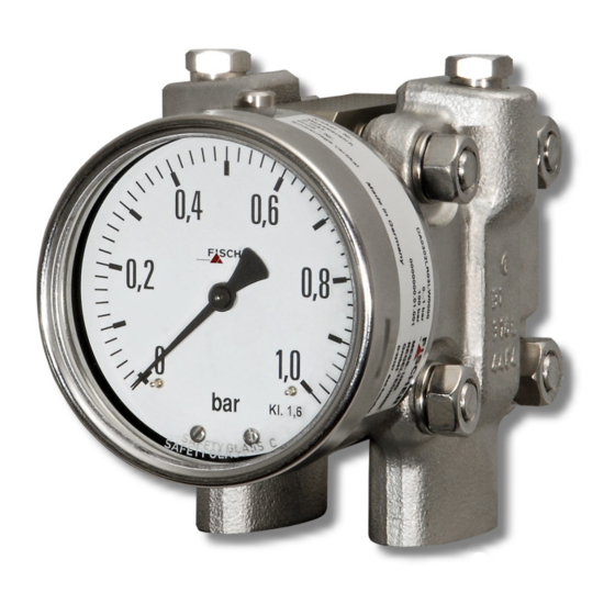
2 | Product and functional description FISCHER Mess- und Regeltechnik GmbH 2 Product and functional description 2.1 Delivery scope • Differential pressure measuring device DA03 • Operating Manual 2.2 Equipment versions The following illustrations depict typical combinations of the measuring cell, measured value display and contact elements. - Page 7 FISCHER Mess- und Regeltechnik GmbH Product and functional description | 2 Order Codes Article no DA0302LR03LW0000 Measurement range 0...1 bar P stat. max. 100 bar MESS- u. Contact function KE20S110A3H2 REGELTECHNIK Prod. - No AB1509105.03.121 GmbH Made in Germany D-32107 Bad Salzuflen...
- Page 8 2 | Product and functional description FISCHER Mess- und Regeltechnik GmbH 2.2.5 Assembly Wall mounting Pipe mounting Panel mounting set type 1 Panel mounting set type 2 with panel mounting set with front ring Fig. 6: Assembly types The panel installation fittings can only be used in devices with a small measur- ing cell (Ø75) and a display in the NG100 bayonet ring casing.
- Page 9 FISCHER Mess- und Regeltechnik GmbH Product and functional description | 2 Small measuring cell Ø75 Measurement range 0 ... 0.6 bar 0 ... 1 bar 0 ... 1.6 bar 0 ... 2.5 bar 0 ... 4.0 bar 0 ... 6bar 0 ...
- Page 10 2 | Product and functional description FISCHER Mess- und Regeltechnik GmbH Large measuring cell Ø130 Measurement range 0 ... 40 mbar 0 ... 60 mbar 0 ... 100 mbar 0 ... 160 mbar 0 ... 250 mbar 0 ... 400 mbar -40 ...
-
Page 11: Function Diagram
FISCHER Mess- und Regeltechnik GmbH Product and functional description | 2 2.3 Function diagram Fig. 11: Function diagram Motion train Transfer lever Measuring shaft Pressure transfer fluid Measuring membranes Connecting rod O-ring (pressure relief valve) Pressure chamber 2.4 Design and mode of operation... -
Page 12: Assembly
3 | Assembly FISCHER Mess- und Regeltechnik GmbH 3 Assembly 3.1 General information The device can be mounted in one of the following ways (see Assembly [} 8]): 1. Wall mounting The device is designed for installation onto flat assembly plates. The unit is equipped with a wall mounting plate for this mounting type. -
Page 13: Electrical Connections
FISCHER Mess- und Regeltechnik GmbH Assembly | 3 3.3 Electrical connections • By authorized and qualified specialized personnel only. • When connecting the unit, the national and international electro-technical regulations must be observed. • Disconnect the system from the mains, before electrically connecting the device. - Page 14 3 | Assembly FISCHER Mess- und Regeltechnik GmbH Creep and magnetic spring contacts The terminal numbers always correspond to the contact number an are as- signed to the target indicators from left to right. Up to three contacts can be 1 2 3 4 used.
-
Page 15: Commissioning
FISCHER Mess- und Regeltechnik GmbH Commissioning | 4 4 Commissioning 4.1 General All electrical supply, operating and measuring lines, and the pressure connec- tions must have been correctly installed before commissioning. All supply lines are arranged so that there are no mechanical forces acting on the device. -
Page 16: Zero Point Correction
4 | Commissioning FISCHER Mess- und Regeltechnik GmbH 4.3 Zero point correction The differential pressure measuring units are set in the factory before delivery so that they do not usually need to be adjusted at the assembly site. If this is still necessary, proceed as follows: •... - Page 17 FISCHER Mess- und Regeltechnik GmbH Commissioning | 4 Adjustment sequence: • Press the axle inwards until the drive arm reaches behind the setting pin of the target value indicator. • Set the target value indicator to the required switch point by turning the set- ting key.
-
Page 18: Servicing
5 | Servicing FISCHER Mess- und Regeltechnik GmbH 5 Servicing 5.1 Maintenance The instrument is maintenance-free. We recommend the following regular in- spection to guarantee reliable operation and a long service life: • Check the function in combination with downstream components. -
Page 19: Technical Data
FISCHER Mess- und Regeltechnik GmbH Technical data | 6 6 Technical data 6.1 General information EXECUTION Nominal Measuring Application information pressure cell DA03 S … PN100 Ø75 Measuring ranges: 0…0.6 bar to 0…25 bar Pressure caps 1.4404 or Hastelloy screws A2 Remote seals: It is possible to attach remote seals for all measuring ranges. -
Page 20: Input Variables
6 | Technical data FISCHER Mess- und Regeltechnik GmbH 6.2 Input variables Measuring variable Differential pressure in gaseous and fluid aggressive media. General information Rated pressure of the measuring Max. static operating pressure system Durability One-sided over-pressure-proof up to the... -
Page 21: Operating Conditions
FISCHER Mess- und Regeltechnik GmbH Technical data | 6 6.3 Operating conditions Permissible ambient temperature -40 … +80 °C Admissible storage temperature -40 … +80 °C Admissible media temperature -40 … +80 °C Type of protection: IP 65 acc. to EN 60529 6.4 Construction design... - Page 22 6 | Technical data FISCHER Mess- und Regeltechnik GmbH Assembly Wall mounting Flanged assembly plate Pipe mounting Flanged assembly plate and attachment bracket Panel mounting set Panel installation fittings for units with a small measuring type 1 cell (Ø75) and NG100 bayonet ring casing.
- Page 23 FISCHER Mess- und Regeltechnik GmbH Technical data | 6 6.4.2 Electrical connection In the case of devices with additional electronic equipment, the connection is realised using a cable socket attached to the side and/or with a Han 7D con- nector on th epower plant models. The pin assignment depends on the ordered mode and is stated in the data sheet KE or KE09.
- Page 24 6 | Technical data FISCHER Mess- und Regeltechnik GmbH 6.4.3 Dimensional drawings All dimensions in mm unless otherwise stated Small measuring system (Ø75) 161.5 Wall mounting plate Flange based on DIN EN 61518 Wall mounting plate G½ 7/16 UNF Fig. 23: Dimensional drawing (Small measuring system Ø75) 2"...
- Page 25 FISCHER Mess- und Regeltechnik GmbH Technical data | 6 Large measuring system (Ø130) 196.5 Wall mounting plate Wall mounting plate Flange based on DIN EN 61518 G½ 7/16 UNF Fig. 25: Dimensional drawing (Large measuring system Ø130) Installation of front panel type 1 (only small measuring system Ø75 and NG100 display)
- Page 26 6 | Technical data FISCHER Mess- und Regeltechnik GmbH Installation of front panel type 2 The front plate thickness must be min. 2 mm. Front ring Bayonet ring with connecting bracket NG100 A suitable steel construction must be used to ensure NG160 that the front plate can bear the weight of the device.
- Page 27 FISCHER Mess- und Regeltechnik GmbH Technical data | 6 Contact elements NG100 = 90 NG100 = 138 NG160 = 120 NG160 = 167.5 Fig. 28: Dimensional drawing contact devices Shut-off fitting Cutting ring connection G3/8 with inner spindle thread for 12 mm pipe...
-
Page 28: Order Codes
7 | Order Codes FISCHER Mess- und Regeltechnik GmbH 7 Order Codes Code no. Type Device model: Pressure level Measuring cell PN100 Ø75 PN160 Ø75 PN100 Ø130 PN160 Ø130 Measuring range: Small measuring system [2.3] Measurement range Device model Ø75 0…0.6 bar... - Page 29 FISCHER Mess- und Regeltechnik GmbH Order Codes | 7 Large measuring system [2.3] Measurement range Device model Ø130 0 … 40 mbar ● ● 0 … 60 mbar ● ● 0 … 100 mbar ● ● 0 … 160 mbar ●...
-
Page 30: Accessories
7 | Order Codes FISCHER Mess- und Regeltechnik GmbH Fluid filling: Without fluid filling Silicon oil Special functions: [10] Without special function Adjustable marker needle Resettable drag needle Contacts/transmitters: [11] No contacts/transmitters Built-in contacts as per data sheet KE Installed capacitive rotation angle transducer in accordance with data... -
Page 31: Eu Declarations Of Conformity
FISCHER Mess- und Regeltechnik GmbH EU Declarations of conformity | 8 8 EU Declarations of conformity Fig. 30: CE_EN_DA03...10 BA_EN_DA03_SR_NM 31/36... - Page 32 8 | EU Declarations of conformity FISCHER Mess- und Regeltechnik GmbH Fig. 31: CE_EN_DA03...20 32/36 BA_EN_DA03_SR_NM...
-
Page 33: Ukca Declarations Of Conformity
FISCHER Mess- und Regeltechnik GmbH UKCA Declarations of Conformity | 9 9 UKCA Declarations of Conformity Fig. 32: UKCA_EN_DA03_10 BA_EN_DA03_SR_NM 33/36... - Page 34 9 | UKCA Declarations of Conformity FISCHER Mess- und Regeltechnik GmbH Fig. 33: UKCA_EN_DA03_20 34/36 BA_EN_DA03_SR_NM...
-
Page 35: 10Eac Declaration
FISCHER Mess- und Regeltechnik GmbH EAC Declaration | 10 10 EAC Declaration Fig. 34: ЕАЭС N RU Д-DЕ.АЛ16.В.77754 BA_EN_DA03_SR_NM 35/36... - Page 36 Mess- und Regeltechnik GmbH Bielefelder Str. 37a D-32107 Bad Salzuflen Tel. +49 5222 974-0 Fax +49 5222 7170 www.fischermesstechnik.de info@fischermesstechnik.de Technische Änderungen vorbehalten. Subject to technical changes. Sous réserve de modifications techniques.
Need help?
Do you have a question about the DA03 SR/NM and is the answer not in the manual?
Questions and answers