
Related Manuals for Woodward EM-80


Summary of Contents for Woodward EM-80
- Page 1 Released Product Manual 26761 (Revision E, 12/2017) Original Instructions EM-80/EM-300 Actuator System Installation and Operation Manual...
- Page 2 Woodward reserves the right to update any portion of this publication at any time. Information provided by Woodward is believed to be correct and reliable. However, no responsibility is assumed by Woodward unless otherwise expressly undertaken.
- Page 3 AC Power Line Filter ..................... 13 Necessary Cables ....................13 4. EM-80/-300 A ............19 HAPTER CTUATOR General ......................... 19 EM-80/-300 Actuator Mounting ................19 EM-80/-300 Actuator Temperature Derating ............22 Engine Linkage Information .................. 23 5. D ........28 HAPTER RIVER VERVIEW AND NSTALLATION General Description ....................
- Page 4 Released EM-80/EM-300 Actuator System Manual 26761 Contents (cont'd.) A. E (EMC) ......65 PPENDIX LECTROMAGNETIC OMPATIBILITY Introduction ......................65 Cabling ........................66 Grounding ......................67 Screening ......................68 B. D ............70 PPENDIX RIVER RROR VENTS C. S ..............90 PPENDIX ISPOSAL D. EM-80/-300 D ..
- Page 5 Figure 3-2b. Control Wiring Diagram (right half) ..........16 Figure 3-2c. Control Wiring Diagram (notes) ............17 Figure 4-1a. Actuator Outline Drawing (EM-80) ........... 20 Figure 4-1b. Actuator Outline Drawing (EM-300) ..........21 Figure 4-2. Ambient Temperature vs Torque ............22 Figure 5-1.
- Page 6 Start-up On- and off-highway Mobile Applications: Unless Woodward's control functions as the supervisory control, customer should install a system totally independent of the prime mover control system that...
- Page 7 Do not touch the components or conductors on a printed circuit board with your hands or with conductive devices. To prevent damage to electronic components caused by improper handling, read and observe the precautions in Woodward manual 82715 , Guide for Handling and Protection of Electronic Controls, Printed Circuit Boards, and Modules.
- Page 8 Released EM-80/EM-300 Actuator System Manual 26761 Regulatory Compliance European Compliance for CE Mark (Stöber): Low Voltage Directive: Directive 2014/35/EU on the harmonization of the laws of the Member States relating to the making available on the market of electrical equipment designed for use within certain voltage limits.
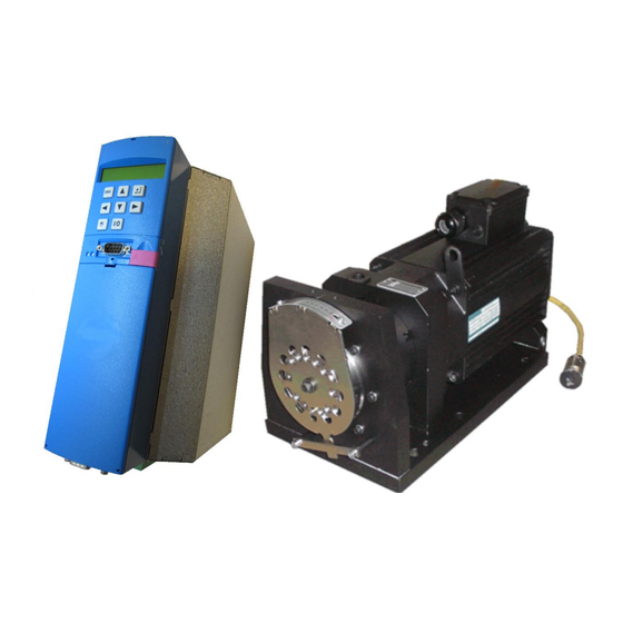
- Page 9 EM-80/-300, please refer to the specific Woodward documentation supplied with each product. For specific operating information such as start-up, shutdown, and the prime mover's response to signals from the Woodward control, refer to the prime mover manufacturer's manual. Description of Components The EM-80/-300 system provides an all-electric actuation system for various prime mover control applications.
- Page 10 EM-80/EM-300 Actuator System Manual 26761 The actuator is available in two versions: the EM-80 and the EM-300. Both consist of a high-performance, three-phase brushless AC motor that drives a precision planetary gearbox. A resolver on the motor provides a position feedback signal.
- Page 11 Released Manual 26761 EM-80/EM-300 Actuator System Do not replace or substitute Woodward products and components with non- Woodward devices without authorization from Woodward. Observe all applicable regulations during installation. PE (protective earth ground]) connections as shown in this document are required to avoid personal injuries caused by high voltages.
- Page 12 If external damage has occurred, assess the damage that may have also occurred to the components. If the components may have been damaged, contact the transportation carrier and Woodward. Make sure the carrier completes a transportation damage report immediately. If any parts are missing, contact Woodward.
- Page 13 1:20 gear ratio. The motor–gearbox combination comes assembled on a mounting bracket with a fixed hole pattern. Although the EM-300 is longer than the EM-80, both use the same mounting hole pattern, allowing the actuators to be interchangeable.
- Page 14 The EM-80 uses only the resolver since the 1:7 gear ratio within the gearbox allows full stroke of the actuator output flange with less than one full revolution of the motor shaft.
- Page 15 Released Manual 26761 EM-80/EM-300 Actuator System AC Power Line Filter A 3-phase AC power line filter is used to reduce the influence of any interference that may occur due to the power source. It also protects the power source from emissions that may occur due to the driver.
- Page 16 EM-80/EM 300 system. Modification of this cable can have an influence on overall system EMC robustness, so any changes must be performed with close attention to grounding and shielding.
- Page 17 Released Manual 26761 EM-80/EM-300 Actuator System NEUT AC LINE TIMER 240VAC Figure 3-2a. Control Wiring Diagram (left half) (see Notes in Figure 3-2c ) Woodward...
- Page 18 Released EM-80/EM-300 Actuator System Manual 26761 EM-300 Only Motor Resolver Figure 3-2b. Control Wiring Diagram (right half) (see Notes in Figure 3-2c) Woodward...
- Page 19 Woodward personnel. If the resistor is damaged during usage or installation, replace If needed to replace broken resistor use only Woodward EM-80/300 resistor kit only with Woodward EM-80/300 resistor kit 8923-2313 to properly set 8923-2313 to properly set 4-20mA input range 4-20mA input range.
- Page 20 Released EM-80/EM-300 Actuator System Manual 26761 Metal Electrical Enclosure The EM driver must be installed inside a metal electrical enclosure (cabinet) that is grounded (bonded) to earth. Cable shields must be electrically grounded (bonded) to the enclosure. See Figures A-1 and A-3 in Appendix A for additional details.
- Page 21 The EM-80 and EM-300 actuator both use a similar mounting pattern (see Figure 4-1). Six 12 mm or 0.5” fasteners are used to attach the EM-80 actuator to its mounting surface. Eight 12 mm or 0.5” fasteners are used to attach the EM-300 actuator to its mounting surface.
- Page 22 Released EM-80/EM-300 Actuator System Manual 26761 Figure 4-1a. Actuator Outline Drawing (EM-80) Woodward...
- Page 23 Released Manual 26761 EM-80/EM-300 Actuator System Figure 4-1b. Actuator Outline Drawing (EM-300) Woodward...
- Page 24 EM-80/-300 Actuator Temperature Derating The ambient air temperature surrounding the actuator must not exceed 85 °C. In addition, the temperature of the mounting surface must be controlled such that the mounting plate of the actuator never exceeds 85 °C.
- Page 25 Figure 4-1 shows the hole pattern for the EM-80 and EM-300 actuator output flange. The EM-80 has 11 M6x1 holes with a maximum flange depth of 11 mm. The EM-300 has 11 M8x1.25 holes with a maximum flange depth of 14 mm. In...
- Page 26 Released EM-80/EM-300 Actuator System Manual 26761 Note 1—The net available torque is the torque that is available for acceleration. This is the maximum torque of the actuator after correction for temperature (refer to the graph in Figure 4-2) minus the torque required to move the rack and overcome friction.
- Page 27 Released Manual 26761 EM-80/EM-300 Actuator System EM-80 10-90% Slew Time Approximations 0.8000 0.7000 0.6000 0.5000 10-90 % 0.4000 Slew Time [seconds] 0.3000 0.2000 0.1000 0.0000 Rack torque [Nm] Rack inertia [kgm EM-300 10-90% Slew Time Approximations 0.7000 0.6000 0.5000 0.4000...
- Page 28 Manual 26761 Stops and Pointer Design The EM-80 and EM-300 actuator does not have internal stops. The stroke of the actuator output flange is limited electronically in the driver to 40°. For clockwise rotation, the relation between degrees and V: 1 V = 0°...
- Page 29 The variation in the position of the output flange of any actuator relative to its mounting plate is less than ±0.45°. Therefore, exchanging actuators should require minimal recalibration of the linkage system. The pitch circular diameter for the output lever on the EM-80 is different from the one on the EM-300. Maximum Side Loading...
- Page 30 The driver is field- configurable for the type of actuator (EM-80 or EM-300) and the desired direction of output shaft rotation (CW or CCW). The default parameters as shipped from...
- Page 31 Installation HIGH VOLTAGE—The power converter's power cables are energized. The Contact of the Ready for Use Output on X101 of the EM-80/- 300 driver must be integrated into the Emergency Shutdown system of the prime mover. Stopping the drive using the enable inputs of the control electronics does not by itself represent a safe stop condition.
- Page 32 Released EM-80/EM-300 Actuator System Manual 26761 Installation of the Driver in the Switch Cabinet It is essential to comply with the following installation instructions to avoid device and property damage. The driver must be installed in the switching cabinet. The installation site must be free of dust, corrosive fumes and all kinds of liquids.
- Page 33 Released Manual 26761 EM-80/EM-300 Actuator System The units must be installed in commercially available cabinets that meet the following requirements. Ventilation must be in the specified direction from the bottom to the top. Ensure that the flow of air is not obstructed.
- Page 34 Released EM-80/EM-300 Actuator System Manual 26761 It is important to keep a minimum free spacing from the driver to provide better ventilation during the installation. Ensure that there is no blockage of cooling air flowing into and out of the driver for a safe operation.
- Page 35 Over or under voltage of the 24 Vdc supply can lead to loss of position control of the actuator and/or damage to the controller. For reliable operation, the EM-80/-300 requires this source to be in the range of 20.4 Vdc to 28.8 Vdc.
- Page 36 3 x 30 A fusing will be adequate for the EM-80/-300 driver applications, providing the installation wiring can handle these currents comfortably.
- Page 37 Released Manual 26761 EM-80/EM-300 Actuator System The driver is also equipped with the option of removing the internal EMC filters by removing two identified screws on the side of the housing. For TN and TT power networks, the internal filters must remain installed for proper EMC performance.
- Page 38 In addition to the DB-15 connector at one end of the cable, this cable has three flying leads for EM-300 potentiometer feedback signals: POT_V, POT(+), POT(–). For usage with an EM-80 actuator, the unused flying leads need to be electrically insulated from touching metallic surfaces, or one another, and secured to the harness using tie wraps or similar.
- Page 39 60 m 5450-1738 (RETROFIT ADAPTOR) Table 5-7. Resolver Cables Available from Woodward Position Command Input (X100) This is the signal from the engine controller and represents the required actuator position. The analog input (analog input 1) of the driver accepts a 4–20 mA input with a shunt load of 406 Ohm provided by the parallel combination of an internal and external resistor.
- Page 40 The 1–5 V output signal corresponds to 0–40 degree stroke of the actuator’s output shaft. Woodward recommends that the end user monitors the Position Readout for enhanced system error detection. The Position Readout signal is meant only as an indicator of output shaft position.
- Page 41 X100 terminal per wiring diagram (Figure 3-2) when either an EM-80 or EM-300 actuator is in use. While the EM-80 does not use the potentiometer input, this wiring can help detect an incorrect configuration when using the configurable version of the driver.
- Page 42 The Ready for Use signal is de-energized when the 24 Vdc supply drops below 16.8 Vdc or the PLC stops functioning. Emergency shutdown valves and other safety devices necessary to avoid damage or injury should be set to activate any time a shutdown fault is detected by the EM-80/-300 driver. Woodward...
- Page 43 Released Manual 26761 EM-80/EM-300 Actuator System See Figure 3-2 for the most common wiring scheme for the Ready for Use output. Driver X101 +24V Power Supply FAULT TRIP STRING X101 Terminals Table 5-11. Ready For Use Output Wiring Whenever the Ready For Use output changes state, the Common...
- Page 44 X101, BE1 (pin 10). To further enhance safety, Woodward also recommends that if E-Stop is wired in systems, also configure the system supervisory controller (supplied by end user) to command the analog demand input to minimum position when E-Stop is activated.
- Page 45 Released Manual 26761 EM-80/EM-300 Actuator System Reset Discrete Input (X101 Connector) This signal is a digital input which, when active, will serve as means to acknowledge active alarms and if the cause of the fault has been removed, reset the device for proper function. The same functionality can be achieved be pressing the “ESC”...
- Page 46 Released EM-80/EM-300 Actuator System Manual 26761 Common Alarm Output (X101 Connector) This signal is a discrete contact output for indicating the health of the 3-phase driver and actuator position errors. If the driver circuitry goes off-line, or a position error is detected, the common alarm output will change state from closed to open.
- Page 47 Fault (See LCD display for relevant fault RUN(green) information) ERROR (red) Flashing at 8 Hz No configuration active RUN (green) Before proceeding with commissioning, it is recommended to check the cable connection. Woodward provides a resolver cable in various lengths (see Table 5-7). Woodward...
- Page 48 Released EM-80/EM-300 Actuator System Manual 26761 Event Indications Events Event indications on the display give the user information on a state of the device. The event list (Appendix B) gives user a list of event indications. The device provides notes on the cause of some of the events. These events are marked with a number and appear alternatively to the event indicators on the display.
- Page 49 Woodward for assistance in having the oil replaced by the gearbox manufacturer at five-year intervals. The gearbox is sealed, and it is not possible to replace the oil without complete disassembly.
- Page 50 Released EM-80/EM-300 Actuator System Manual 26761 Chapter 8. Troubleshooting Introduction Read and follow all safety instructions given in Chapter 1, General Safety Precautions. Improper engine operation is often the result of factors other than governor operation. This chapter gives tips about engine problems which can resemble governor problems.
- Page 51 Internal mechanical failure—replace actuator. Actuator Problems If the EM-80/-300 actuator fails to run, do the following actions. Verify any fault indications on the driver. If the actuator appears jammed, then: Monitor the actuator current. If the current is low, the actuator is not jamming.
- Page 52 Released EM-80/EM-300 Actuator System Manual 26761 Electrical Troubleshooting Guide Perform the following activities only when the engine is stopped and locked out, and the EM-system is fully powered down. EM-SYSTEM Ignoring this information can result in death, severe TROUBLESHOOTING personal injury, or considerable damage to property.
- Page 53 Released Manual 26761 EM-80/EM-300 Actuator System The resolver type can be determined based on the results of measurements in Table 8-1 above. Do not disassemble the resolver housing as this may cause internal damage or result in malfunctioning of the actuator.
- Page 54 Released EM-80/EM-300 Actuator System Manual 26761 Pin to Pin Diagram Cable Cable Cable Cable Cable 12-Pin Length Length Length Length Length DB15 Round 10 m 20 m 30 m 40 m 60 m Connector Connector Function Number Approximated Resistance in Ohms...
- Page 55 Released Manual 26761 EM-80/EM-300 Actuator System Verify the jumper is in place between X100, pins 1 and 2. This jumper connects with the internal resistor for proper scaling. Analog Output If the analog output is not functioning properly, verify the following: ...
- Page 56 (Figures 3-2a-b-c) and Table 8-2 in Chapter 8. Verify that the application is correct. This input is only active for the EM-300 actuator, not for the EM-80 actuator. Verify that X100 pin 6 measures 10 V +/- 0.1V when referenced to X100 pin 8.
- Page 57 10k Ohm +/- 5%. If the continuity of the resistance of the potentiometer still is intermitted or measured value lies outside of value from Table 8-3 please contact your Woodward support representative to EM-300 replace or re-calibrate potentiometer. POTENTIOMETER...
- Page 58 Released EM-80/EM-300 Actuator System Manual 26761 Motor Temperature Input If the motor temperature input is not functioning properly, verify the following: Check the wiring, look at the connections at X140 pins 7 and 14 for disconnected or misconnected cables. See Figures 3-2a-b-c: Control Wiring Diagram for more details.
- Page 59 Released Manual 26761 EM-80/EM-300 Actuator System Chapter 9. Specifications Specifications General Specifications EM-80 EM-300 Nominal Torque Output (continuous) * 91 Nm (67 lb-ft) 260 Nm (192 lb-ft) Maximum Torque Output (1 second max) 190 Nm (140 lb-ft) 429 Nm (316 lb-ft) 40°, no internal...
- Page 60 Released EM-80/EM-300 Actuator System Manual 26761 DRIVER GENERAL SPECIFICATIONS General Driver Electrical Specifications Command Input 4–20 mA Power Supply 3 phase, 400–480 Vac, 50–60 Hz, ±10% Rated Input Current 20 A 15 A (12 A eff.), 0 to 45 °C, derated to 10.5 A Rated Output Current (8.4 A eff.) at 55 °C...
- Page 61 Released Manual 26761 EM-80/EM-300 Actuator System DRIVER CIRCUIT SPECIFICATIONS Circuit Specifications 4–20 mA Analog Input Specifications Input Resolution 15 bits 2 kΩ (external) || 510Ω (internal) 406 Ω total Total shunt resistance Low Signal Fault Detection < 3.6 mA High Signal Fault Detection >...
- Page 62 Released EM-80/EM-300 Actuator System Manual 26761 DRIVER CIRCUIT SPECIFICATIONS (cont’d) Filter Specifications Rated Current 30 A Peak Current 32.9 A for < 1 min per hour at 40 °C Connection Voltages 3 x 520 Vac, 50–60 Hz, ±10% –25 to +100 °C (–13 to +212 °F)
- Page 63 A Recognized Turbine Retrofitter (RTR) is an independent company that does both steam and gas turbine control retrofits and upgrades globally, and can provide the full line of Woodward systems and components for the retrofits and overhauls, long term service contracts, emergency repairs, etc.
- Page 64 Flat Rate Remanufacture: Flat Rate Remanufacture is very similar to the Flat Rate Repair option with the exception that the unit will be returned to you in “like- new” condition and carry with it the full standard Woodward product warranty (Woodward Product and Service Warranty 5-01-1205). This option is applicable to mechanical products only.
- Page 65 Engineering Services Woodward offers various Engineering Services for our products. For these services, you can contact us by telephone, by email, or through the Woodward website. Technical Support ...
- Page 66 Manual 26761 Technical Assistance If you need to contact technical assistance, you will need to provide the following information. Please write it down here before contacting the Engine OEM, the Packager, a Woodward Business Partner, or the Woodward factory: General...
- Page 67 To ensure EMC, you must observe the configuration information below. Installation of other electronic equipment inside the cabinet that encloses the EM-80/EM-300 requires that the cabling for this equipment meet the same requirements that the cabling for the EM-80/EM-300 meets. See this appendix for further details.
- Page 68 Released EM-80/EM-300 Actuator System Manual 26761 Cabling To suppress radiated noise outside the converter, you should screen all the connected cabling. See also "Screening" later in this appendix. Cables (wires) can act as an antenna, picking up (or transmitting) undesirable signals.
- Page 69 Released Manual 26761 EM-80/EM-300 Actuator System Avoid reserve loops on overlong cables. You must ground spare lines at both ends (this has an additional screening effect, and avoids capacitive-coupled, dangerous touch voltages). Grounding From an EMC point of view, classical “star” grounding is no longer adequate for reducing the influence of disturbances at relatively high frequencies that occur as a result of converter operation.
- Page 70 Released EM-80/EM-300 Actuator System Manual 26761 Screening The screen is effective against magnetic fields if it is connected to frame ground at both ends. With electrical fields, the screen is effective when it is connected to frame ground at one end. However, in the case of (electrical or magnetic) fields with high frequencies (depending on the length of the line), you must always connect the screen at both ends due to the linkage (electromagnetic field).
- Page 71 Released Manual 26761 EM-80/EM-300 Actuator System Figure A-5. Suggestion for Screen Connection Woodward...
- Page 72 Released EM-80/EM-300 Actuator System Manual 26761 Appendix B. Driver Error Events 31:Short/ground Trigger Level Reaction Acknowledgement The hardware short-circuit Fault The motor coasts down Switch the device off/on or switch-off is active reset input Potential Cause Test Measure Check the motor windings (see “Electrical...
- Page 73 Released Manual 26761 EM-80/EM-300 Actuator System 33:Overcurrent Trigger Level Reaction Acknowledgement The total motor current Fault The motor coasts down Switch the device off/on or exceeds the permitted reset input maximum value Potential Cause Test Measure Internal fault None Contact your service supplier...
- Page 74 Released EM-80/EM-300 Actuator System Manual 26761 36:High voltage Trigger Level Response Acknowledgement The voltage in the intermediate Fault The motor coasts down Switch the device off/on or circuit exceeds the permitted reset input maximum Potential Cause Test Measure Supply voltage too high...
- Page 75 Released Manual 26761 EM-80/EM-300 Actuator System 38:TempDev.sens Trigger Level Response Acknowledgement The temperature measured by Fault The motor coasts down Switch the device off/on or the device sensor exceeds reset input either the maximum or minimum value Potential Cause Test...
- Page 76 Released EM-80/EM-300 Actuator System Manual 26761 40:Invalid data Trigger Level Response Acknowledgement A data error was detected Fault The driver cannot be enabled Cannot be acknowledged when initializing the non- volatile memory Potential Cause Test Measure Internal fault None Contact your service supplier...
- Page 77 Released Manual 26761 EM-80/EM-300 Actuator System 44: Actuator blocked Trigger Level Response Acknowledgement The load torque exceeds the Fault The motor coasts down Switch the device off/on peak torque output within the first ten seconds after boot-up Potential Cause Test Measure Ensure the load torque doesn’t exceed...
- Page 78 Released EM-80/EM-300 Actuator System Manual 26761 46:Low voltage Trigger Level Response Acknowledgement The intermediate voltage has Fault The motor coasts down Switch the device off/on or dropped below 180 V for more reset input than 5 seconds or DC link voltage has dropped...
- Page 79 Released Manual 26761 EM-80/EM-300 Actuator System 52:Communication Trigger Level Response Acknowledgement Communication fault Fault The motor coasts down Switch the device off/on or reset input Potential Cause Test Measure Internal fault None Contact your service supplier 55:Option Board Trigger Level...
- Page 80 Released EM-80/EM-300 Actuator System Manual 26761 56:Overspeed Trigger Level Response Acknowledgement The measured motor shaft Fault The motor coasts down Switch the device off/on or Fault #68 “Resolver error” is speed exceeds the overspeed reset input threshold. triggered Potential Cause...
- Page 81 105% of reset input thermal overload threshold Potential Cause Test Measure Internal fault None Contact your service supplier 60:Wrong Actuator (EM-80 only) Trigger Level Response Acknowledgement Voltage measured in AE2 >3 V Fault The motor coasts down Switch the device off/on...
- Page 82 Ensure all shielding specified in the wiring in the wiring diagram. diagram has been followed. Apply Woodward’s EMI (Electromagnetic Interference) Make sure Woodward’s recommendations for recommendation for correct correct grounding/shielding have been followed grounding/shielding Ensure the driver boots up Actuator’s output shaft moved...
- Page 83 Released Manual 26761 EM-80/EM-300 Actuator System 61:High mA signal Trigger Level Response Acknowledgement Current measured in AE1>24 mA Fault The motor coasts down Switch the device off/on Potential Cause Test Measure Wrong configuration and/or faulty mA Check whether the position demand...
- Page 84 Released EM-80/EM-300 Actuator System Manual 26761 63:Wrong reference Trigger Level Response Acknowledgement Fault #37 ”Encoder” has been Fault The motor coasts down Switch the device off/on triggered or The measured output shaft position goes below -3.5˚ or above 43.5˚ or...
- Page 85 Released Manual 26761 EM-80/EM-300 Actuator System 64:Pos DMD lost Trigger Level Response Acknowledgement Current measured in AE1<3.6 mA Fault The motor coasts down Switch the device off/on or reset input Potential Cause Test Measure Wrong configuration and/or faulty mA Check whether the position demand...
- Page 86 Released EM-80/EM-300 Actuator System Manual 26761 65:Position error Trigger Level Response Acknowledgement The measured output shaft Alarm The motor keeps running Self-acknowledge position differs ±1˚ from the position command for more than one second Potential Cause Test Measure Ensure the load torque doesn’t exceed...
- Page 87 Released Manual 26761 EM-80/EM-300 Actuator System 67:Enable low Trigger Level Response Acknowledgement Enable input is low Alarm The motor remains disabled Self-acknowledge Potential Cause Test Measure Wiring fault Check whether discrete input BE1 is Take measures to correct the wiring fault...
- Page 88 Released EM-80/EM-300 Actuator System Manual 26761 69:Motor connect. Trigger Level Response Acknowledgement Motor connection error Fault The motor coasts down Switch the device off/on or reset input Potential Cause Description Measure Wrong connection of the power cable Make sure the phase consistency (U, V,...
- Page 89 Released Manual 26761 EM-80/EM-300 Actuator System #xxx:undef’d Int Trigger Level Response Acknowledgement Configuration error Fault The motor coasts down Switch the device off/on Potential Cause Test Measure EMI (Electromagnetic Interference) Ensure all shielding specified in the Apply all shielding specified in the wiring wiring diagram has been followed.
- Page 90 Released EM-80/EM-300 Actuator System Manual 26761 #00b:NMI occurred Trigger Level Response Acknowledgement There is a hardware fault Fault The motor coasts down Cannot be acknowledged Potential Cause Test Measure Internal fault None Contact your service supplier (All of the errors in this list are detailed in the table below)
- Page 91 Released Manual 26761 EM-80/EM-300 Actuator System configuration stopped Trigger Level Response Acknowledgement Configuration stopped Fault The motor coasts down Switch the device off/on Potential Cause Test Measure Internal fault None Contact your service supplier *ParaModul ERROR: file not found no configuration...
- Page 92 Released EM-80/EM-300 Actuator System Manual 26761 Appendix C. Safe Disposal Disposal of Driver/Actuator The equipment consists of the following components and materials: Component Material Housing, various intermediate panels, fan impeller, Sheet steel mounting panels Heat sink in the power stage...
- Page 93 This appendix covers the application where a customer has a mission-critical purpose for keeping their engine running upon failure of the primary three-phase power system that is used for operating the EM-80/300 driver. The EM-80/300 driver has the ability to operate under single-phase conditions to keep the prime mover under operation, so the customer may elect to install a backup single- phase system and the associated switchgear to take advantage of this feature.
- Page 94 Released EM-80/EM-300 Actuator System Manual 26761 Important: These limits are set considering the worst case scenario. The value of the maximum limits increase as the load applied to the output shaft at the moment of switching decreases. For this sequence to be effective under all circumstances, it must operate within the above limits.
- Page 95 Woodward recommends that end users implement a 3-minute wait period whenever switching 3-phase power to off. This ensures a sufficient amount of time for the EM-80/-300 Driver to cool. Before Applying Power Carefully check all cable wiring to ensure proper connection before applying any power to the system.
- Page 96 Manual 26761 Appendix E. Driver Application Type Setup Woodward strongly recommends that the following procedure is performed only by a qualified installer, possessing a solid working knowledge of the system in which this product is utilized. If the application changes described in this appendix are performed without full consideration of the prime mover system, the result may be serious personal injury or death, or property damage.
- Page 97 Press “Enter key”. Navigate to the parameter P11 using the up and down keys, then press “Enter key”. Depending on the current configuration, either “0: EM-80” or “1: EM-300” appears blinking on the second line of the display: Blinkin By using the up and down keys set the value of P11 according to the motor...
- Page 98 Released EM-80/EM-300 Actuator System Manual 26761 By using the up and down keys, set the value of P10 according to the direction of rotation (see table below): P10 value Corresponding key Rotation sense Down key Up key 10. Press “Enter key”. The selected value should not blink anymore.
- Page 99 “ESC” needs to be pressed three times. 19. Power cycle the driver. Once the driver is installed, Woodward recommends stroking the actuator to verify the rotation sense. Make sure the actuator is not connected to any linkage and that there are no potential damages to personnel and/or equipment during the stroke test.
- Page 100 Released EM-80/EM-300 Actuator System Manual 26761 2. Navigate to the “P.. cust. Parameter” menu, using the right and left keys. 3. Press “Enter key”. 4. Navigate to the parameter P14 using the up and down keys, then press “Enter key”. Depending on the current configuration a value appears blinking on the second line of the display.
- Page 101 Released Manual 26761 EM-80/EM-300 Actuator System 9. Navigate to the parameter A00 using the up and down keys if needed, then press “Enter key”. “0: inactive” should appear blinking on the second line of the display. Blinking 10. Press the up key to save the values. This will save the changes made to the control.
- Page 102 Released EM-80/EM-300 Actuator System Manual 26761 When the parameter P15 is set to ‘1’, the actuator output shaft will remain powered at all times and will park at the minimum position during a demand position fault below 3.6mA. In this mode, the...
- Page 103 Released Manual 26761 EM-80/EM-300 Actuator System Blinking 5. By using the up and down keys, set the value of P15 according to the required action (see table below): P15 value Corresponding Key Fault #64 Behavior “Alarm”. No need to reset the fault,...
- Page 104 Released EM-80/EM-300 Actuator System Manual 26761 Revision History Changes in Revision E— Added warnings, cautions, and notices on how to prepare for and proceed with troubleshooting Corrected value of motor windings resistance Corrected pin numbers and values of resolver resistance ...
- Page 105 Released Manual 26761 EM-80/EM-300 Actuator System Declarations Woodward...
- Page 106 Released EM-80/EM-300 Actuator System Manual 26761 Woodward...
- Page 107 Released Manual 26761 EM-80/EM-300 Actuator System THIS PAGE INTENTIONALLY LEFT BLANK Woodward...
- Page 108 26761E Please reference publication ËB26761E´ ¹ ´ ¸ · ¹ Î PO Box 1519, Fort Collins CO 80522-1519, USA 1041 Woodward Way, Fort Collins CO 80524, USA Phone +1 (970) 482-5811 Fax +1 (970) 498-3058 Email and Website—www.woodward.com Woodward has company-owned plants, subsidiaries, and branches, as well as authorized distributors and other authorized service and sales facilities throughout the world.
Need help?
Do you have a question about the EM-80 and is the answer not in the manual?
Questions and answers